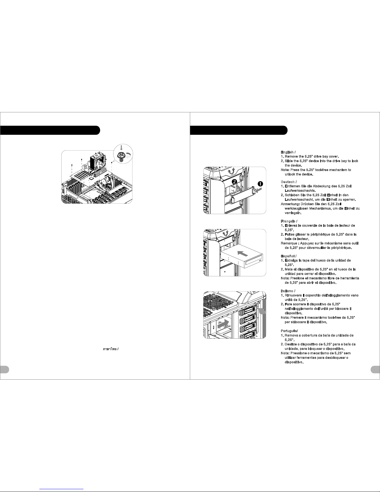
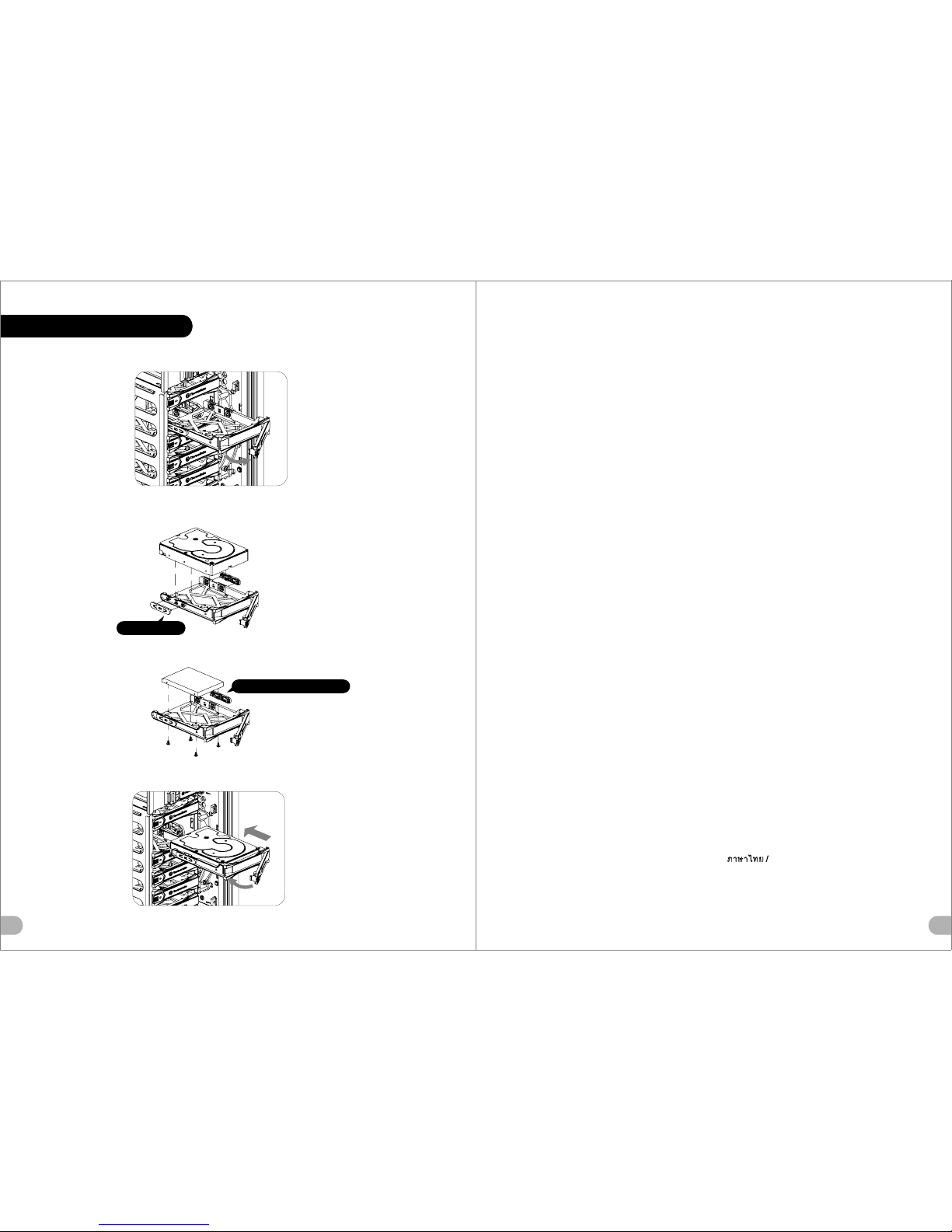
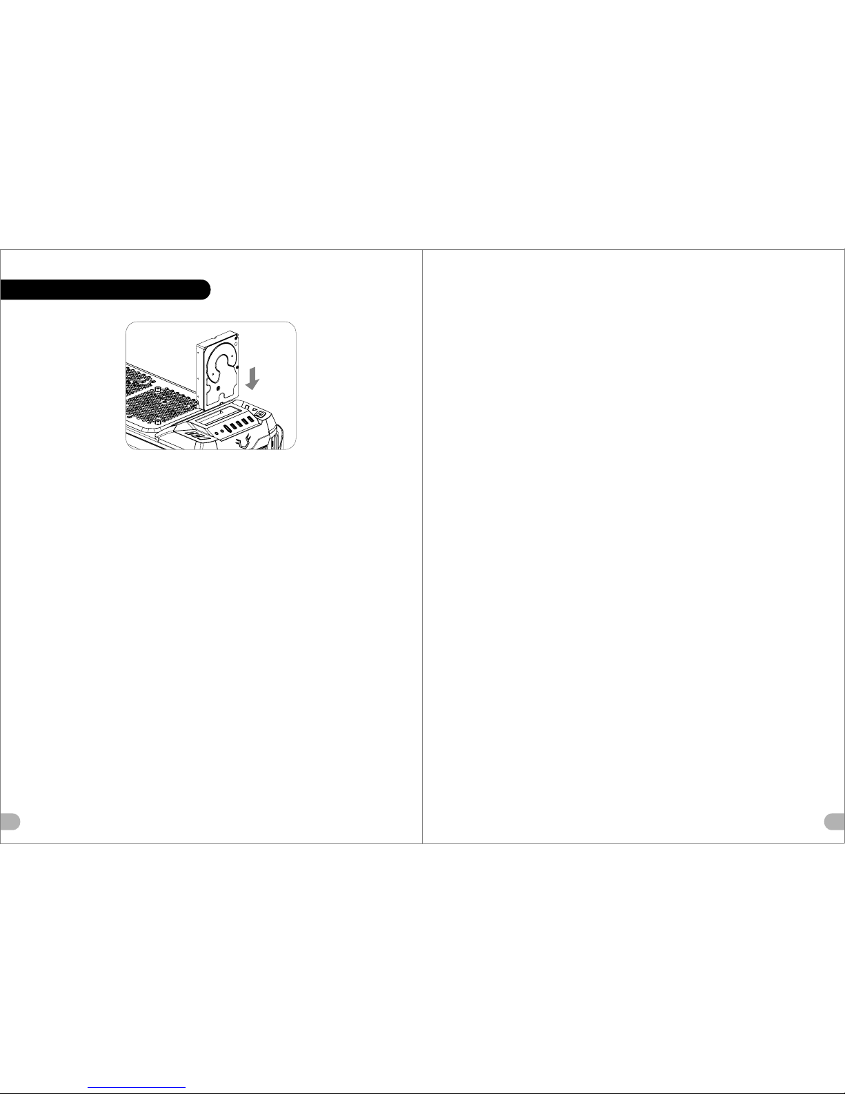
manuals.online logo
Brands
  1. Home
  2. •
  3. Brands
  4. •
  5. Thermaltake
  6. •
  7. Desktop
  8. •
  9. Thermaltake VO200M1W2N User manual

Thermaltake VO200M1W2N User manual

лчиттничюнльтцию.
глтчн.Бзвыдны
www.sotmarket.ru
дбняинфмциятв,
тзывы,бзыиы
Инструкция
Armor REVO VO200M1W2N
Thermaltake
Перейти в карточку товара
8 800 775 98 98
User's ManualBenutzerhandbuchMode d󰾺emploiManual del usuarioManuale dell󰾺utenteManual do Utilizador 󴬪󷡾󷩋󵖯󵚙󶓉󵇗󵇬󴄫󲂇󲂝󲁗󲂝󲁛󲁿󲁬󲂆󲁃󲂌 kullanc elkitab(EEE Yönetmeliine Uygundur)
© 2012 Thermaltake Technology Co., Ltd. All Rights Reserved. 2012.01
All other registered trademarks belong to their respective companies.www.thermaltake.comTested To ComplyWith FCC StandardsFOR HOME OR OFFICE USE VO2000 Series
The legend is back
󷕮󷈓󶵻󵠾󶁛󴯛󴮙󵦺󶣛󾺭󷩬󴊠󴌑󴇘󳶫󴍜󾺢󶓃󴑢󵔺󷘀VO2000 SeriesARMOR Revo󷩋󵖯󵚙11/12/16A󶓃󴑢󴎮󶧒󴌑󴇘󸞦󶚏󴫱󳺗󵔺󷘀󶘝󶧠󵖆󵛀󶇩󵛍
󸦯 󸥍 󸅹3280󵚙󴮌󶲺󴕏󷈓󶃂󶃂󴄗󳹷󶈚󵬫󷗶󶎧󵓩󵜽󷠉󸜃󷗶󶎧2󴌻󴹇(g/m)󷡾󷦣󵕚󴺰󵛱󷲋󸞢󵔙󴌑󴇘󷈓󴼊󷤰󵟝󵧄󴺰󵔕󵛍 MARKETINGCHECKDESIGNPRODUCT GMPeipei󴆡󵧂󶵻125 mm176 mm
Chapter 1. Product IntroductionSpecificationAccessoryWarning and Notice1.01.11.2010102ContentsChapter4 OtherToughpower/TR2/Litepower power supply series (optional)4.029Chapter 2. Installation Guide2.02.12.22.32.42.52.62.72.82.92.10Side Panels DisassemblyPower Supply Unit (PSU) InstallationMotherboard Installation5.25󰾾 Drives Installation3.5󰾾 Drive InstallationHDD InstallationHDD Docking StationPCI Card InstallationKeyboard & Mouse Security Lock UsageFan Speed & Light Control Operation240mm Radiator Installation0405060709101217181921Chapter3 Leads Installation GuideCase LED connectionUSB 2.0 connectionUSB 3.0 connectionAudio connection3.03.13.23.322222222SpecificationFigureParts NameQ'tyUsed forAccessoryTransparent WindowSide PanelI/O PortsStandard PS2 PSU (optional)Supports 1/2" ,3/8" ,1/4" water tube PSULCS UpgradableNet Weight9.6" x 9.6" (Micro ATX), 12" x 9.6" (ATX) (VO200M1W2N)(VO200M6W2N)Full TowerCase TypeExpansion SlotsMotherboardsSECCMaterialDrive BaysAccessibleHiddenCooling System Dimension(H*W*D)Model4 x 5.25󰾺󰾺, 1 x 3.5󰾺󰾺 (Converted from one 5.25󰾾 drive bay)6 x 3.5󰾺󰾺 or 2.5󰾺󰾺1 x 3.5󰾺󰾺 or 2.5󰾺󰾺811.5 kg / 25.35 lb586x 254 x 552 mm( 23.1 x 10 x 21.7 inch)USB 3.0 x 2, USB 2.0 x 2, eSATA x 1, HD Audio x 1(support AC󰾺97 & HD Audio) HDD DockingFront (intake) : 200 x 200 x 30 mm Blue LED fan x 1 (600~800rpm, 13~15dBA)Rear (exhaust) : 140 x 140 x 25 mm Turbo fan x1 (1000rpm,16dBA)Top (exhaust) :200 x 200 x 30 mm Blue LED fan x1 (600~800rpm, 13~15dBA)140 x 140 x 25 mm or 120 x 120 x 25 mm (optional)Side (intake) :Plug&Play 200 x 200 x 30 mm fan x 1 (600~800rpm, 13~15dBA)Bottom (Intake) : 120 x 120 x 25 mm fan x1 (optional) 5.25" To 3.5" Cage5.25" To 3.5" Bay CoverAdapter CableBuzzerCable TieScrew #6-32*4.8mmScrew #6-32*6mmScrew M3*5mmStandoff #6-32Screw Ø3*5mmScrew Ø5*12mmScrew #6-32*35mm111110820243484For FDD/3.5"HDD/2.5"HDDFor FDDFor CPU Power Extension Cable For AlarmFor Settle CableFor Motherboard/HDDFor HDD/Motherboard/PCIFor ODD/FDD/2.5"HDD/RadiatorFor MotherboardFor 5.25" to 3.5"CageFor FanFor FanARMOR REVOARMOR REVO Snow Edition1󷕮󷈓󶵻󵠾󶁛󴯛󴮙󵦺󶣛󾺭󷩬󴊠󴌑󴇘󳶫󴍜󾺢󶓃󴑢󵔺󷘀VO2000 SeriesARMOR Revo󷩋󵖯󵚙11/12/16A󶓃󴑢󴎮󶧒󴌑󴇘󸞦󶚏󴫱󳺗󵔺󷘀󶘝󶧠󵖆󵛀󶇩󵛍
󸦯 󸥍 󸅹3280󵚙󴮌󶲺󴕏󷈓󶃂󶃂󴄗󳹷󶈚󵬫󷗶󶎧󵓩󵜽󷠉󸜃󷗶󶎧2󴌻󴹇(g/m)󷡾󷦣󵕚󴺰󵛱󷲋󸞢󵔙󴌑󴇘󷈓󴼊󷤰󵟝󵧄󴺰󵔕󵛍 MARKETINGCHECKDESIGNPRODUCT GMPeipei󴆡󵧂󶵻125 mm176 mm
Warning and Notice
<180 mm<330 mm
Warning!!CPU Cooler Height Limitation: Please ensure that your CPU cooler does NOT exceed 180mm (7.1 inches) height.VGA (Add-on card) Length Limitation:Please ensure that your VGA (Add-on card) does NOT exceed 330mm (13 inches) length.Warnung!!CPU-Kühler Höhenbeschränkung:Bitte stellen Sie sicher, dass Ihr CPU-Kühler 180 mm (7,1 Zoll) Höhe nicht überschreitet.VGA (Add-on-Karte) Längenbeschränkung:Bitte stellen Sie sicher, dass Ihre VGA (Add-on-Karte) 330 mm (13,0 Zoll) Länge nicht überschreitet.Avertissement !Limite de hauteur du ventilateur de CPU :Vérifiez que la hauteur du ventilateur de CPU ne dépasse pas 180 mm.Limite de longueur de la carte (complémentaire) VGA :Vérifiez que la longueur de votre carte (complémentaire) VGA ne dépasse pas 330 mmPrecauciónLimitación de altura del refrigerador de CPU:Asegúrese de que la altura de su refrigerador de CPU no excede los 180 mm (7,1 pulgadas).Limitación de longitud de la tarjeta de vídeo (adicional):Asegúrese de que la longitud de su tarjeta de vídeo (adicional) no excede los 330 mm (13,0 pulgadas).Attenzione!Limitazione altezza dissipatore CPU:Assicurarsi che l󰾺altezza del dissipatore CPU NON superi 180 mm (7,1 pollici).Limitazione lunghezza VGA (scheda aggiuntiva):Assicurarsi che la lunghezza del VGA (scheda aggiuntiva) NON superi 330 mm (13,0 pollici).Atenção!!Limite de altura para o dissipador do CPU:O limite de altura para o dissipador do CPU é 180 mm (7,1 polegadas).CPU 󴅘󴌜󴘉󶘥󸩹󴹇󸗱󴇗󾺻󷩬󶡛󳽾 CPU 󴅘󴌜󴘉󶘥󸩹󴹇󳶮󷴦󷿯 180 mm (7.1 󷊒󴎬)󱾣VGA (󸗥󴉁󳹬󸜃󴌂) 󶘥󸔘󴹇󸗱󴇗󾺻󷩬󶡛󳽾 VGA (󸗥󴉁󳹬󸜃󴌂) 󶘥󸔘󴹇󳶮󷴦󷿯 330 mm (13 󷊒󴎬)󱾣CPU 󵔄󶂎󴘉󸩹󴹇󸗱󴇗󾺻󷮘󶠏󳽾 CPU 󵔄󶂎󴘉󶘥󸩹󴹇󳶮󷴦󷽨 180 mm󾺩7.1 󷊒󴮙󾺪󱾣VGA󾺩󸗥󴉁󴌂󾺪󸔠󴹇󸗱󴇗󾺻󷮘󶠏󳽾 VGA󾺩󸗥󴉁󴌂󾺪󶘥󸔠󴹇󳶮󷴦󷽨 330 mm󾺩13 󷊒󴮙󾺪󱾣CPU󲁐󲂝󲂊󲂝󲀏󸩹󱿶󴇗󸗱:CPU󲁐󲂝󲂊󲂝󲀏󸩹󱿶󱿭180mm󲀳󷴦󱿩󲀇󱿥󲀋󱿥󱿴󲀉󲀳󶡛󷨮󱿸󲀇󱿰󲀁󱿶󱿥󱾣VGA󾺩󲁃󲁪󲁋󲂔󲁌󲂝󲁪󾺪󲀏󸔘󱿶󴇗󸗱:VGA󾺩󲁃󲁪󲁋󲂔󲁌󲂝󲁪󾺪󲀏󸔘󱿶󱿭330mm󲀳󷴦󱿩󲀇󱿥󲀋󱿥󱿴󲀉󲀳󶡛󷨮󱿸󲀇󱿰󲀁󱿶󱿥󱾣    ,     ( )   180  (7,1 ).    VGA ( ),    VGA ( )   330  (13,0 ).CPU Soutucu Yükseklik Snrlamas:Lütfen CPU soutucunuzun yüksekliinin 180mm󰾺yi (7,1 inç) GEÇMEDNDEN emin olun.VGA (Eklenti kart) Uzunluk Snrlamas:Lütfen VGA󰾺nzn (Eklenti kart) uzunluunun 330mm󰾺yi (13,0 inç) GEÇMEDNDEN emin olun.Limite de comprimento para VGA (placa gráfica):O limite de comprimento para VGA (placa gráfica) é 330 mm (13 polegadas).!!       CPU:        CPU  180 mm (7,1 ).    VGA ( ):     VGA ( )  330 mm (13 ).󷬇󴏫󾺢󾺢󷬇󴏫󾺢󾺢󷬇󴏫!Uyar!!!! CPU: CPU  180 . (7.1 ) VGA (): VGA ()  330 . (13 )23󷕮󷈓󶵻󵠾󶁛󴯛󴮙󵦺󶣛󾺭󷩬󴊠󴌑󴇘󳶫󴍜󾺢󶓃󴑢󵔺󷘀VO2000 SeriesARMOR Revo󷩋󵖯󵚙11/12/16A󶓃󴑢󴎮󶧒󴌑󴇘󸞦󶚏󴫱󳺗󵔺󷘀󶘝󶧠󵖆󵛀󶇩󵛍
󸦯 󸥍 󸅹3280󵚙󴮌󶲺󴕏󷈓󶃂󶃂󴄗󳹷󶈚󵬫󷗶󶎧󵓩󵜽󷠉󸜃󷗶󶎧2󴌻󴹇(g/m)󷡾󷦣󵕚󴺰󵛱󷲋󸞢󵔙󴌑󴇘󷈓󴼊󷤰󵟝󵧄󴺰󵔕󵛍 MARKETINGCHECKDESIGNPRODUCT GMPeipei󴆡󵧂󶵻125 mm176 mm
Side Panels DisassemblyEnglish /Remove the screws on the back of the chassis, and open the side panelDeutsch /Entfernen Sie die Schrauben auf der Rückseite des Gehäuses und öffnen Sie das SeitenteilFrançais /Enlevez les vis à l󰾺arrière du châssis et ouvrez le panneau latéralEspañol /Extraiga los tornillos de la parte posterior de la caja y abra el panel lateralItaliano /Rimuovere le viti sulla parte posteriore dello chassis e aprire il pannello lateralePortuguês/Remova os parafusos na parte de trás da caixa e abra o painel lateral󶷢󸩵󳷎󵔨 /󶦜󸘅󵨀󵭝󴼭󵕚󷝛󶴓󾺭󴮨󴀕󶨸󵇴󸔬󵖆󵛍󷨿 /󲁘󲂄󲂝󲁘󷁭󸜃󲀏󲀎󱿹󲀳󴍷󲀫󴢷󱿸󱾢󲁖󲁅󲁪󲁲󲁮󲂌󲀳󸔬󱿮󲀟󱿺 /         󶬡󳻴󳷎󵔨 /󴌙󸘅󵛛󴢔󴎯󵕚󷝛󳶾󾺭󴮧󳽈󶨸󵇴󴺡Türkçe /Kasann arkasndaki vidalar çkarn ve yan paneli açn / /        ,     English /Deutsch /Français /1. Placez l󰾺alimentation dans la position appropriée.2. Ajustez le pont de support de l󰾺alimentation dans la position appropriée et fixez l󰾺alimentation à l󰾺aide des vis.Español /1. Instale la PSU en la ubicación correcta.2. Ajuste el puente de soporte de la PSU en la ubicación adecuada y asegúrela con tornillos.1. Place the PSU in proper location.2. Adjust the PSU supporting bridge to the proper location and secure the PSU with screws.1. Platzieren Sie das Netzteil in der richtigen Position.2. Richten Sie die Stützbrücke für das Netzteil entsprechend aus und sichern Sie das Netzteil mit Schrauben.Power Supply Unit (PSU) Installation󶬡󳻴󳷎󵔨 /󵖆󵛍󷨿 / /Italiano /󶷢󸩵󳷎󵔨 /󶬡󳻴󳷎󵔨 /󵖆󵛍󷨿 / /1.      .2.            .Türkçe /1. Posizionare la PSU in modo corretto.2. Regolare il ponticello di supporto della PSU nella posizione corretta e fissare la PSU con delle viti.Português/1. Coloque o PSU na sua devida posição.2. Ajuste a ponte de suporte do PSU para a devida posição e fixe o PSU com parafusos./1.      .2.               .1. 󴮨󸚜󵸱󳼼󵅪󴘉󵓟󴛉󵬄󶡛󶘥󳻮󶼏2. 󴮨󸚜󵸱󳼼󵅪󴘉󵓐󵐱󵝗󷩠󵔕󴇑󸀊󶔗󶘥󳻮󶼏󾺭󶃗󴼭󶓉󷝛󶴓󴚛󴬻󸚜󵸱󳼼󵅪󴘉󱾣1. 󴮧󶓖󵸱󳼼󴸵󴘉󵓟󴛉󵬄󶠏󶘥󳻮󶼏2. 󴮧󶓖󵸱󳼼󴸵󴘉󵓐󵐲󵝗󷮤󵔕󴇑󷾣󴻴󶘥󳻮󶼏󾺭󶃗󴎯󶓉󷝛󳶾󴚛󴬻󶓖󵸱󳼼󴸵󴘉󱾣1. PSU󲀳󸀊󴆨󲀋󲂎󲁒󲂝󲁘󲂈󲂔󲀌󴍷󲀫󳹹󱿲󲀟󱿺󱾣2. PSU󵓐󵊢󲁷󲂋󲁤󲁙󲀳󸀊󴆨󲀋󲂎󲁒󲂝󲁘󲂈󲂔󲀌󴎩󱿧󲀩󱿧󲀌󷩠󵔕󱿸󱾢󲀎󱿹󲀈PSU󲀳󶶁󲀢󳹹󱿲󲀟󱿺󱾣1. PSU󰾺yu, uygun konuma yerletirin.2. PSU destek köprüsünü uygun konuma ayarlayn ve PSU󰾺yu vidalarla sabitleyin. /1.  PSU 2.  PSU   PSU 45󷕮󷈓󶵻󵠾󶁛󴯛󴮙󵦺󶣛󾺭󷩬󴊠󴌑󴇘󳶫󴍜󾺢󶓃󴑢󵔺󷘀VO2000 SeriesARMOR Revo󷩋󵖯󵚙11/12/16A󶓃󴑢󴎮󶧒󴌑󴇘󸞦󶚏󴫱󳺗󵔺󷘀󶘝󶧠󵖆󵛀󶇩󵛍
󸦯 󸥍 󸅹3280󵚙󴮌󶲺󴕏󷈓󶃂󶃂󴄗󳹷󶈚󵬫󷗶󶎧󵓩󵜽󷠉󸜃󷗶󶎧2󴌻󴹇(g/m)󷡾󷦣󵕚󴺰󵛱󷲋󸞢󵔙󴌑󴇘󷈓󴼊󷤰󵟝󵧄󴺰󵔕󵛍 MARKETINGCHECKDESIGNPRODUCT GMPeipei󴆡󵧂󶵻125 mm176 mm
Motherboard InstallationEnglish /1.Lay down the chassis.2.Install the motherboard in proper location and secure it with screws.Deutsch /1.Legen Sie das Gehäuse auf die Seite.2.Installieren Sie die Hauptplatine in ihrer vorgesehenen Position und sichern Sie sie mit Schrauben. Français /1.Posez à plat le châssis.2.Installez la carte mère dans l'endroit approprié et sécurisez-la avec des vis.Español /1. Tumbe el chasis.2. Instale la placa madre en la ubicación adecuada y asegúrela con tornillos.Italiano /1.Poggiare lo chassis.2.Installare la scheda madre nella posizione appropriata e fissarla con le viti.Português/1. Deixe a caixa.2. Instale a motherboard no local adequado e aparafuse./1.    .2.            .󶷢󸩵󳷎󵔨 /1. 󴮨󵨀󵭝󴸔󵓟󱾣2. 󴮨󳷜󵨀󵜠󵓟󶼏󴛉󴎩󸀊󶘥󳻮󶼏󳷇󶓉󸚗󳺗󴊦󳷎󳷬󷝛󶴓󴚛󴬻󱾣󵖆󵛍󷨿 /1.󲁘󲂄󲂝󲁘󲀳󳶬󲀌󶼏󱿮󲀟󱿺󱾣2.󲁿󲁗󲂝󲁽󲂝󲁪󲀳󸀊󴆨󲀋󴟕󵇡󲀌󴍷󲀫󳹹󱿲󱾢󲀎󱿹󲀈󴚛󴬻󱿸󲀟󱿺󱾣 /1.   . 2.          .󶬡󳻴󳷎󵔨 /1. 󵓟󴸔󵛛󶭒󱾣2. 󴛉󴎩󷾣󶘥󳻮󶼏󴬪󷡦󳷜󵜠󴸗󳺆󷝛󳶾󴬪󴄉󴚛󴬻󱾣Türkçe /1.Kasay yan yatrn.2.Ana kart uygun konuma takn ve vidalarla sabitleyin. /1.2.5.25󰾾 Drives InstallationEnglish /1. Remove the 5.25󰾾 drive bay cover.2. Slide the 5.25󰾾 device into the drive bay to lock the device.Note: Press the 5.25󰾾 tool-free mechanism to unlock the device.Deutsch /1. Entfernen Sie die Abdeckung des 5,25 Zoll Laufwerksschachts.2. Schieben Sie the 5,25 Zoll Einheit in den Laufwerksschacht, um die Einheit zu sperren.Anmerkung: Drücken Sie den 5,25 Zoll werkzeuglosen Mechanismus, um die Einheit zu verriegeln.Français /1. Enlevez le couvercle de la baie de lecteur de 5,25".2. Faites glisser le périphérique de 5,25" dans la baie de lecteur.Remarque : Appuyez sur le mécanisme sans outil de 5,25" pour déverrouiller le périphérique.Español /1. Extraiga la tapa del hueco de la unidad de 5,25".2. Meta el dispositivo de 5,25󰾾 en el hueco de la unidad para cerrar el dispositivo.Nota: Presione el mecanismo libre de herramienta de 5,25󰾾 para abrir el dispositivo.Italiano /1. Rimuovere il coperchio dell󰾺alloggiamento vano unità da 5,25󰾺󰾺.2. Fare scorrere il dispositivo da 5,25󰾾 nell󰾺alloggiamento dell󰾺unità per bloccare il dispositivo.Nota: Premere il meccanismo tool-free da 5,25󰾾 per sbloccare il dispositivo.Português/1. Remova a cobertura da baía da unidade de 5,25".2. Deslize o dispositivo de 5,25" para a baía da unidade, para bloquear o dispositivo.Nota: Pressione o mecanismo de 5,25" sem utilizar ferramentas para desbloquear o dispositivo.67󷕮󷈓󶵻󵠾󶁛󴯛󴮙󵦺󶣛󾺭󷩬󴊠󴌑󴇘󳶫󴍜󾺢󶓃󴑢󵔺󷘀VO2000 SeriesARMOR Revo󷩋󵖯󵚙11/12/16A󶓃󴑢󴎮󶧒󴌑󴇘󸞦󶚏󴫱󳺗󵔺󷘀󶘝󶧠󵖆󵛀󶇩󵛍
󸦯 󸥍 󸅹3280󵚙󴮌󶲺󴕏󷈓󶃂󶃂󴄗󳹷󶈚󵬫󷗶󶎧󵓩󵜽󷠉󸜃󷗶󶎧2󴌻󴹇(g/m)󷡾󷦣󵕚󴺰󵛱󷲋󸞢󵔙󴌑󴇘󷈓󴼊󷤰󵟝󵧄󴺰󵔕󵛍 MARKETINGCHECKDESIGNPRODUCT GMPeipei󴆡󵧂󶵻125 mm176 mm
3.5󰾾 Drive InstallationEnglish / . 1. Remove the 5.25󰾾 mesh cover. 3.     2. Secure the 3.5󰾾 device on the adapter by screws.     5,25󰾾,  3. Slide the adapter into free 5.25󰾾 bay, then mount     5,25󰾾  the 5.25󰾾 to 3.5󰾾 mesh cover to the front panel.3,5󰾾  .Deutsch /1. Entfernen Sie die Netzabdeckung des 5,25 Zoll 󶷢󸩵󳷎󵔨 /1. 󶦜󸘅5.25󰾾󵒕󴃦󵦞󵨵󵜠Laufwerksschachts. 2. 󴮨3.5󰾾󷡾󶼏󵓟󴄆󷻪󵍆󶡢󵝗󳷇󶓉󷝛󶴓󴚛󴬻3.5󰾾󷡾󶼏2. Sichern Sie die 3,5 Zoll Einheit mit Schrauben auf 3. 󵍳󴄆󷻪󵍆󶡢󵝗󷆔󸀊󶔗󶘥󳻮󶼏󾺭󴮨5.25󰾾󷻪3.5󰾾󸏖󶵓󴬪dem Adapter. 󷡾󷆔󴇮󸜃󵜠3. Schieben Sie den Adapter in eine freie 5,25 Zoll Bucht, dann montieren Sie die 5,25 Zoll zu 3,5 Zoll 󶬡󳻴󳷎󵔨 /Netzabdeckung an der Frontseitenkonsole.1. 󶦜󸘅5.25󰾾󵦞󶙷2. 󶓉󷝛󳶾󴮧3.5󰾾 󴢷󸂉󷭟󴢨󴬪󷡦󴛉󷼍󵍆󵝗󴄦Français /3. 󴮧󷼍󵍆󵝗󵹲󴄆󵦞󴄦󾺭󴬪󷡦 5.25󰾾 󷼍 3.5󰾾 󶻲󶙷󷆔󴇮󸜃1. Retirez le couvercle grillagé de 5,25" 󵜠2. Fixez le périphérique de 3,5" à l'adaptateur à l'aide de vis. 󵖆󵛍󷨿 /3. Faites glisser l󰾺adaptateur dans une baie de 5,25" 1. 5.25"󲂂󲁤󲁘󲂆󲁌󲁱󲂝󲀳󴍷󲀫󴢷󱿸󲀟󱿺󱾣 2. 3.5󰾾󲁨󲁱󲁅󲁚󲀳󲀎󱿹󲀈󲁃󲁡󲁸󲁠󲀌󴚛󴬻󱿸󲀟󱿺󱾣 disponible, puis fixez le couvercle grillagé de 5,25" 3. 󲁃󲁡󲁸󲁠󲀳5.25󰾾󲁺󲁅󲀌󲁚󲂊󲁅󲁪󱿶󱿼󲀇󱿬󲀪󱾢vers 3,5" sur le panneau avant.5.25󰾾󾻿3.5󰾾󲂂󲁤󲁘󲂆󲁌󲁱󲂝󲀳󲁶󲂎󲂔󲁩󲁲󲁮󲂌󲀌󲁿Español /󲁇󲂔󲁩󱿸󲀟󱿺󱾣1. Extraiga la tapa de malla de 5,25". 2. Fije el dispositivo de 3,5󰾾 en el adaptador con los  /tornillos. 1.      3. Introduzca el adaptador en el hueco de 5,25󰾾, a 5,25- . continuación monte la tapa de malla de 5,25󰾾 a 3,5󰾾 2.  3,5-   en el panel frontal.   . 3.       Italiano /5,25-    1. Rimuovere il coperchio a maglie da 5,25󰾾.    «5,25-  2. Fissare il dispositivo da 3,5󰾾 sull󰾺adattatore con 3,5- »   .delle viti. 3. Fare scorrere l󰾺adattatore nel vano da 5,25󰾾 libero, Türkçe /quindi montare il coperchio a maglie da 5,25󰾾 a 3,5󰾾 1. 5,25" zgara kapan çkarn. sul pannello anteriore.2. 3,5󰾾 aygtn adaptöre vidalarla sabitleyin. 3. Adaptörü bo 5,25󰾾 bölmesinin içine kaydrn ve Português/daha sonra, 5,25󰾾 - 3,5󰾾 zgara kapan ön 1. Remova a cobertura de rede de 5,25". panele monte edin.2. Fixe o dispositivo de 3,5" ao adaptador com parafusos. 3. Deslize o adaptador para a baía de 5,25" livres e 1.  5.25"  monte a cobertura de rede de 5,25" a 3,5" para o 2.  3.5"  painel dianteiro.3.  5.25"   / 5.25"  3.5"  1.     5,25󰾾. 2.    3,5󰾾     //1.       5,25󰾾.2.    5,25󰾾          .:    " " 5,25󰾾     .󶷢󸩵󳷎󵔨 /1. 󶦜󸘅5.25󰾾󵒕󴃦󵦞󵨵󵜠2. 󴮨5.25󰾾󷡾󶼏󷆔󸀊󶔗󶘥󳻮󶼏󵲉󵂰: 󴤣󸚡󶦜󸘅5.25󰾾󷡾󶼏󾺭󴃩󵊪󴡴5.25󰾾󶃂󷝛󵨀󵨀󵥬󾺭󴄮󴮨5.25󰾾󷡾󶼏󴼡󴇮󵍉󴆛󱾣󶬡󳻴󳷎󵔨 /1. 󶦜󸘅5.25󰾾󵦞󶙷2. 󴮧5.25󰾾󷭟󴢨󵹲󴄆󸨒󴉉󴘉󵦞󵲉󵂰: 󴤣󸚡󶦜󸘅5.25󰾾󷭟󴢨󾺭󴃩󵊪󴌬5.25󰾾󴃮󶓉󴶆󴄘󵛛󵡑󷡦󶼏󾺭󴄮󴮧5.25󰾾󷭟󴢨󴼡󴇮󵍉󴆛󵖆󵛍󷨿 /1. 5.25󰾾󲁪󲂊󲁅󲁷󲁺󲁅󲀏󲁌󲁱󲂝󲀳󴍷󲀫󴢷󱿸󲀟󱿺󱾣2. 5.25󰾾󲁨󲁱󲁅󲁚󲀳󲁪󲂊󲁅󲁷󲁺󲁅󲀌󲁚󲂊󲁅󲁪󱿶󱿼󲀇󲁨󲁱󲁅󲁚󲀳󲂎󲁤󲁐󱿸󲀟󱿺󱾣󵲉: 5.25󰾾󴶆󴄘󳶮󷤢󲂂󲁌󲁬󲁛󲂁󲀳󵉝󱿸󲀇󲁨󲁱󲁅󲁚󲀳󲁃󲂔󲂎󲁤󲁐󱿸󲀟󱿺󱾣 /1.     5,25- .2.  5,25-      ..          5,25- ,   .Türkçe /1. 5,25" sürücü bölmesi kapan çkarn.2. 5,25󰾾 aygtn kilitlemek için sürücü bölmesinin içine doru kaydrn.Not: Aygtn kilidini açmak için 5,25󰾾 araçsz mekanizmay bastrn.1.  5.25" 2.  5.25" :  5.25"  /89󷕮󷈓󶵻󵠾󶁛󴯛󴮙󵦺󶣛󾺭󷩬󴊠󴌑󴇘󳶫󴍜󾺢󶓃󴑢󵔺󷘀VO2000 SeriesARMOR Revo󷩋󵖯󵚙11/12/16A󶓃󴑢󴎮󶧒󴌑󴇘󸞦󶚏󴫱󳺗󵔺󷘀󶘝󶧠󵖆󵛀󶇩󵛍
󸦯 󸥍 󸅹3280󵚙󴮌󶲺󴕏󷈓󶃂󶃂󴄗󳹷󶈚󵬫󷗶󶎧󵓩󵜽󷠉󸜃󷗶󶎧2󴌻󴹇(g/m)󷡾󷦣󵕚󴺰󵛱󷲋󸞢󵔙󴌑󴇘󷈓󴼊󷤰󵟝󵧄󴺰󵔕󵛍 MARKETINGCHECKDESIGNPRODUCT GMPeipei󴆡󵧂󶵻125 mm176 mm
HDD InstallationEnglish /1.Press a latch to pull the tray out.2. Remove the locking clips then position the HDD in the tray and secure the HDD with the locking clips.3. Slide the tray back to the drive bay.Deutsch /1. Drücken Sie auf eine Lasche, um den Schacht herauszuziehen.2. Entfernen Sie die Halte-Clips, positionieren Sie dann die HDD in dem Schacht und befestigen Sie die HDD mit den Halte-Clips. 3. Schieben Sie den Schacht zurück in den Laufwerksschacht.Français /1. Appuyez sur un loquet pour enlever le boîtier.2. Enlevez les clips de verrouillage puis placez le disque dur dans le boîtier et fixez le disque dur avec les clips de verrouillage.3. Refaites glisser le boîtier dans la baie de lecteur.Español /1. Presione un pasador para extraer la bandeja.2. Extraiga los ganchos de bloqueo, coloque el disco duro en la bandeja y fíjelo con los ganchos de bloqueo.3. Vuelva a meter la bandeja en el hueco de la unidad.Italiano /1. Stringere un laccio per estrarre il vano.2. Rimuovere le clip di bloccaggio, quindi posizionare l󰾺HDD nel vano e fissarlo con le clip di bloccaggio.3. Fare scorrere il vano verso l󰾺alloggiamento dell󰾺unità.Português/1. Prima um trinco para puxar a bandeja para fora.2. Remova os clipes de bloqueio e posicione o disco rígido na bandeja. Prenda o disco rígido com os clipes de bloqueio.3. Deslize a bandeja de volta para a baía da unidade./1.         .2.                      .3.         .󶷢󸩵󳷎󵔨 /1. 󷺶󴡴󶠍󶡀󵇹󶚅󴶇󴀕󸔬󴔀󶠍󶡀󵇹󶚅󾺭󳷇󴎲󴢷󵉪󴆛󶠍󶡀󵇹󶚅󱾣2. 󴃩󶦜󸘅󴶇󴎔2󶇨󵈄󴄘󾺭󴮨󶠍󶡀󵓟󷆔󵕝󶠍󶡀󵇹󶚅󳶫󾺭󵈄󴄘󵈄󴙿󴚛󴬻󶠍󶡀󱾣3. 󴮨󶠍󶡀󵇹󶚅󵓟󴙿󶠍󶡀󶡢󵝗󳷎󾺭󵊪󴡴󶠍󶡀󵇹󶚅󵈫󵇬󳺆󴚛󴬻󶠍󶡀󱾣󶬡󳻴󳷎󵔨 /1. 󴌬󳶬󴃮󶓉󴶆󴄘󵛛󵡑󷡦󶼏󳺆󴌙󳶬󶠍󶙹󵇹󶙹󾺭󶃗󴎯󵉪󴆛󵇹󶙹󱾣2. 󴌙󳶬2󳷋󵈄󴄘󾺭󴮧󶠍󶙹󸨒󴉉󴘉󵓟󶼏󴛉󵇹󶙹󳶫󾺭󶃗󴎯󴌬󴙿󵈄󴄘󴚛󴬻󱾣3. 󴮧󶠍󶙹󵇹󶙹󵹲󴙿󶠍󶙹󶙳󾺭󴸗󵊪󳶬󵈫󵇬󳺆󸒢󴬻󶠍󶙹󵇹󶙹󱾣󵖆󵛍󷨿 / 1. 󲂊󲁤󲁢󲀳󵉝󱿸󲀇󲁩󲂍󲁅󲀳󴺶󱿮󴆛󱿸󲀟󱿺󱾣2. 󲂎󲁤󲁎󲂔󲁑󲁐󲂋󲁤󲁸󲀳󴍷󲀫󴢷󱿸󲀇󱿬󲀪HDD󲀳󲁩󲂍󲁅󲀌󷧎󶼏󱿸󱾢HDD󲀳󲂎󲁤󲁎󲂔󲁑󲁐󲂋󲁤󲁸󲀈󴚛󴬻󱿸󲀟󱿺󱾣3. 󲁩󲂍󲁅󲀳󲁪󲂊󲁅󲁷󲁺󲁅󲀟󲀈󲁚󲂊󲁅󲁪󱿶󱿼󲀇󵇜󱿸󲀟󱿺󱾣 /1.  ,   .2.  ,         .3.      .Türkçe /1. Tepsiyi dar çekmek için bir mandala basn.2. Kilitleme klipsini çkarn ve HDD󰾺yi tepsinin içine yerletirip kilitleme klipsiyle sabitleyin.3. Tepsiyi tekrar sürücü bölmesinin içine kaydrn.1. 2.  3.  /For 3.5" HDD: Secure 3.5" HDD from both side of the HDD tray by locking clips.For 2.5" HDD: Secure 2.5" HDD from the bottom of the HDD by screws.Locking clipsRemove this locking clip1011󷕮󷈓󶵻󵠾󶁛󴯛󴮙󵦺󶣛󾺭󷩬󴊠󴌑󴇘󳶫󴍜󾺢󶓃󴑢󵔺󷘀VO2000 SeriesARMOR Revo󷩋󵖯󵚙11/12/16A󶓃󴑢󴎮󶧒󴌑󴇘󸞦󶚏󴫱󳺗󵔺󷘀󶘝󶧠󵖆󵛀󶇩󵛍
󸦯 󸥍 󸅹3280󵚙󴮌󶲺󴕏󷈓󶃂󶃂󴄗󳹷󶈚󵬫󷗶󶎧󵓩󵜽󷠉󸜃󷗶󶎧2󴌻󴹇(g/m)󷡾󷦣󵕚󴺰󵛱󷲋󸞢󵔙󴌑󴇘󷈓󴼊󷤰󵟝󵧄󴺰󵔕󵛍 MARKETINGCHECKDESIGNPRODUCT GMPeipei󴆡󵧂󶵻125 mm176 mm
HDD Docking StationEnglish /The top HDD Docking slot is embedded to enable ultra fast transfer (up to 3.0Gbps) of large data to a SATA hard disk without having to use an external storage enclosure. To ensure proper operation, please make sure the following settings are correct:- Ensure all required drivers are installed for your motherboard or SATA controller card.- Connect the SATA cable to an available SATA connector on the motherboard or SATA controller card.- Connect the power cable to power supply.- Ensure AHCI (Advanced Host Controller Interface) is enabled on your motherboard or SATA controller card. The AHCI enables for 󰾽hotswap󰾾 capability of the SATA hard drives without having to turn off the computer prior to connecting or disconnecting of the hard drive. Please follow instruction provided by your motherboard or SATA controller card to enable the AHCI function.If you are using a brand new hard drive, the hard drive will need to be initialized (formatted) before it is accessible. For more information on how to initialize (format) a new hard drive, please refer to the hard drive user manual or visit System running on Windows 7: http://www.thermaltakeusa.com/Faq.aspx?ID=1143System running on Windows Vista: http://www.thermaltakeusa.com/Faq.aspx?ID=1079System running on Windows XP: http://www.thermaltakeusa.com/Faq.aspx?ID=1073Deutsch /Der obere Einführungsschlitz der HDD-Dockingstation ist eingelassen, um einen ultraschnellen Transfer (bis zu 3,0 GB/s) von umfangreichen Daten zur SATA-Festplatte zu ermögichen, ohne dafür ein externes Gehäuse verwenden zu müssen. Um einen ordnungsgemäßen Betrieb zu gewährleisten, stellen Sie bitte sicher, dass die folgenden Einstellungen richtig sind:- Stellen Sie sicher, dass alle erforderlichen Treiber für Ihr Mainboard oder SATA Controller-Karte installiert sind. - Verbinden Sie das SATA-Kabel mit einen freien SATA-Anschluss auf dem Mainboard oder der SATA Controller-Karte. - Verbinden Sie das Stromkabel mit dem Netzteil.- Stellen Sie sicher, dass AHCI (Advanced Host Controller Interface) auf dem Motherboard oder der SATA-Controller-Karte aktiviert ist. AHCI ermöglicht die "HotSwap"-Funktion der SATA-Festplatten, ohne dass Sie den Computer ausschalten müssen, bevor Sie die Festplatte anschließen oder entfernen. Bitte folgen Sie den Anweisungen Ihres Motherboards oder der SATA-Controller-Karte, um die AHCI-Funktion zu aktivieren. Wenn Sie eine neue Festplatte benutzen, muss die Festplatte initialisiert werden (formatiert), bevor sie nutzbar ist. Weitere Informationen darüber, wie man eine neue Festplatte formatiert, entnehmen Sie bitte dem Benutzerhandbuch zur Festplatte oder besuchen Sie System läuft unter Windows 7: http://www.thermaltakeusa.com/Faq.aspx?ID=1143System läuft unter Windows Vista:http://www.thermaltakeusa.com/Faq.aspx?ID=1079System läuft unter Windows XP: http://www.thermaltakeusa.com/Faq.aspx?ID=1073Français /La station d󰾺accueil verticale de disque dur est intégrée pour permettre le transfert ultra rapide (jusqu󰾺à 3,0 Gbits/s) de données volumineuses vers un disque dur SATA sans devoir utiliser un boîtier de stockage externe. Pour assurer un bon fonctionnement, veuillez vérifier la justesse des paramètres suivants :- Vérifiez que tous les pilotes requis soient installés pour votre carte mère ou votre carte contrôleur SATA.- Connectez le câble SATA à un connecteur SATA disponible sur la carte mère ou la carte contrôleur SATA.- Connectez le cordon d󰾺alimentation à l󰾺alimentation.- Vérifiez que le mode AHCI (Advanced Host Controller Interface) soit activé sur votre carte mère ou votre carte contrôleur SATA. Le mode AHCI permet « l󰾺échange à chaud » des disques durs SATA sans devoir éteindre l'ordinateur avant de connecter ou de débrancher le disque dur. Veuillez suivre les directives de votre carte mère ou de votre carte contrôleur SATA pour activer la fonction AHCI.Si vous utilisez un disque dur neuf, il devra être initialisé (formaté) avant de devenir accessible. Pour plus d'informations sur comment initialiser (formater) un nouveau disque dur, veuillez vous reporter au manuel de l'utilisateur du disque dur ou visitez Pour un système qui exécute Windows 7 : http://www.thermaltakeusa.com/Faq.aspx?ID=1143Pour un système qui exécute Windows Vista : http://www.thermaltakeusa.com/Faq.aspx?ID=1079Pour un système qui exécute Windows XP : http://www.thermaltakeusa.com/Faq.aspx?ID=1073Español /La ranura de acoplamiento de disco duro principal se aloja para facilitar la transferencia ultra rápida (hasta 3,0 Gbps) de muchos datos a un disco duro SATA sin tener que utilizar una cubierta de almacenamiento externa. Para garantizar un funcionamiento adecuado, asegúrese de que los siguientes ajustes son correctos:- Asegúrese de que están instalados todos los controladores necesarios para la placa base o la tarjeta controladora SATA.- Conecte el cable SATA a un conector SATA disponible de la placa base o la tarjeta controladora SATA.- Conecte el cable de alimentación a la fuente de energía.- Asegúrese de que AHCI (Interfaz de controlador host avanzada) está activada en la placa base o la tarjeta controladora SATA. La AHCI activa la función "intercambio en caliente󰾾 de los discos duros SATA sin tener que apagar el equipo antes de conectar o desconectar el disco duro. Siga las instrucciones proporcionadas por la placa base o la tarjeta controladora SATA para activar la función AHCI.Si utiliza un disco duro nuevo, éste necesitará inicializarse (formatearse) antes de acceder a él. Para obtener más información sobre cómo inicializar (formatear) un disco duro nuevo, consulte el manual del usuario del disco duro o visite Sistema ejecutado en Windows 7: http://www.thermaltakeusa.com/Faq.aspx?ID=1143Sistema ejecutado en Windows Vista:http://www.thermaltakeusa.com/Faq.aspx?ID=1079Sistema ejecutado en Windows XP: http://www.thermaltakeusa.com/Faq.aspx?ID=1143Italiano /Lo slot HDD Docking superiore è integrato e consente un trasferimento ultraveloce (fino a 3,0 Gbps) di grandi quantità di dati in un disco rigido SATA senza dover usare alcun dispositivo di archiviazione interno. Per garantire il corretto funzionamento, verificare che le seguenti impostazioni siano corrette:- Verificare che siano installati tutti i driver richiesti per la scheda madre o la scheda del controller SATA.- Collegare il cavo SATA ad un connettore SATA disponibile nella scheda madre o nella scheda del controller SATA.- Collegare il cavo di alimentazione all󰾺alimentatore.- Verificare che l󰾺interfaccia AHCI (Advanced Host Controller Interface) sia abilitata sulla scheda madre o sulla scheda del controller SATA. L󰾺interfaccia AHCI consente la funzionalità 󰾽hotswap󰾾 delle unità rigide SATA senza dovere spegnere il computer prima di collegare o scollegare il disco rigido. Seguire le istruzioni fornite per la scheda madre o la scheda del controller SATA per abilitare la funzione AHCI.Se si utilizza il disco rigido di una nuova marca, sarà necessario inizializzarlo (formattarlo) per renderlo accessibile. Per ulteriori informazioni sull'inizializzazione (formattazione) di un nuovo disco rigido, consultare il manuale utente del disco rigido oppure verificareil sistema in esecuzione su Windows 7: http://www.thermaltakeusa.com/Faq.aspx?ID=1143Sistema in esecuzione su Windows Vista: http://www.thermaltakeusa.com/Faq.aspx?ID=1079Sistema in esecuzione su Windows XP: http://www.thermaltakeusa.com/Faq.aspx?ID=10731213󷕮󷈓󶵻󵠾󶁛󴯛󴮙󵦺󶣛󾺭󷩬󴊠󴌑󴇘󳶫󴍜󾺢󶓃󴑢󵔺󷘀VO2000 SeriesARMOR Revo󷩋󵖯󵚙11/12/16A󶓃󴑢󴎮󶧒󴌑󴇘󸞦󶚏󴫱󳺗󵔺󷘀󶘝󶧠󵖆󵛀󶇩󵛍
󸦯 󸥍 󸅹3280󵚙󴮌󶲺󴕏󷈓󶃂󶃂󴄗󳹷󶈚󵬫󷗶󶎧󵓩󵜽󷠉󸜃󷗶󶎧2󴌻󴹇(g/m)󷡾󷦣󵕚󴺰󵛱󷲋󸞢󵔙󴌑󴇘󷈓󴼊󷤰󵟝󵧄󴺰󵔕󵛍 MARKETINGCHECKDESIGNPRODUCT GMPeipei󴆡󵧂󶵻125 mm176 mm
Português/O topo da ranhura da Estação base do disco rígido está integrado para permitir uma transferência ultra rápida (até 3.0Gbps) de grandes dados para um disco rígido SATA sem utilizar um disco de armazenamento externo. Para garantir o funcionamento correcto, certifique-se que as seguintes definições estão correctas:- Certifique-se que todos os drivers necessários estão instalados na sua motherboard ou placa de controlador SATA.- Ligue o cabo SATA a um conector SATA disponível na motherboard ou na placa de controlador SATA.- Ligue o cabo de alimentação à fonte de alimentação.- Certifique-se que AHCI (Advanced Host Controller Interface) está activado na sua motherboard ou placa de controlador SATA. O AHCI permite a capacidade "hotswap" dos discos rígidos SATA sem ter de desligar o computador antes de ligar ou desligar o disco rígido. Siga as instruções fornecidas pela sua motherboard ou pela placa de controlador SATA para activar a função AHCI.Se estiver a utilizar um disco rígido novo pela primeira vez, o disco rígido terá de ser iniciado (formatado) antes de estar acessível. Para mais informações sobre como iniciar (formatar) um disco rígido novo, consulte o manual de utilizador do disco rígido ou visite Sistema a funcionar no Windows 7: http://www.thermaltakeusa.com/Faq.aspx?ID=1143Sistema a funcionar no Windows Vista:http://www.thermaltakeusa.com/Faq.aspx?ID=1079Sistema a funcionar no Windows XP: http://www.thermaltakeusa.com/Faq.aspx?ID=1073/               (  3 Gbps)       SATA        .      ,       :-                   SATA.-    SATA    SATA        SATA.-      .-     AHCI (Advanced Host Controller Interface)          SATA.   AHCI        (󰾽hotswap󰾾)    SATA                 .             SATA        AHCI.    ,    ()       .        ()   ,              Windows 7: http://www.thermaltakeusa.com/Faq.aspx?ID=1143    Windows Vista:http://www.thermaltakeusa.com/Faq.aspx?ID=1079    Windows XP: http://www.thermaltakeusa.com/Faq.aspx?ID=1073󶷢󸩵󳷎󵔨 /󴄈󴺛󶠍󶡀󵨀󴞛󴹈󸞣󸂉󵍳󵦞󾺭󶃂󸚡󳼠󶓉󴢷󵍆󴺰󴃓󴫹󵨀󵭝󾺭󵓐󵎕󴣈󴜬󷱨󵔺󴎲 SATA 󶠍󶡀󷴦󴾌󷿀󴁔󷻙 (󴎐󵓐󵎕󵚡󸩹 3.0Gbps)󱾣󶁛󳽾󷫪󵬄󴷙󷿬󳻽󾺭󷩬󶡛󳽾󴤣󳶬󷧎󴬻󵬄󶡛󾺻- 󶡛󳽾󴶓󴬪󷡾󳷜󵨀󵜠󵆷 SATA 󵍈󴇗󴌂󴽦󸚡󶘥󵇡󵚪󸧦󴉶󶦬󴺰󱾣- 󴮨 SATA 󶸽󶵻󷿄󵍆󷆔󳷜󵨀󵜠󳶫󴎐󶓉󶘥 SATA 󵍆󸟎󵆷 SATA 󵍈󴇗󴌂󳶫󱾣- 󴮨󸚜󵸱󶵻󷿄󵍆󷆔󸚜󵸱󳼼󵅪󴘉󳶫󱾣- 󶡛󳽾󴛉󳷜󵨀󵜠󵆷 SATA 󵍈󴇗󴌂󳶫󴔀󶓉 AHCI 󾺩󷿓󸘯󳷜󵨀󵍈󴇗󴘉󳹬󸜃󾺪󱾣AHCI 󷂞󴣁󴔀󶓉 SATA 󶠍󶡀󵨀 󶘥󱾭󶅒󵍳󵉵󱾮󴉀󷂞󾺭󶃂󸚡󳸬󴃩󸕽󸔪󸚜󷄇󴯒󴎐󳺆󷿄󵍆󵆷󵕘󸔬󶠍󶡀󵨀 󱾣󷩬󸀖󶄈󳷜󵨀󵜠󵆷 SATA 󵍈󴇗󴌂󷢞󷿁 󴓧󶘥󷩋󵖯󾺭󴔀󶓉 AHCI 󴉀󷂞󱾣󴤣󵜽󵁉󳼠󶓉󶘥󵗐󴄉󵕑󶘥󶠍󶡀󵨀󾺭󸚡󴮨󴄗󴆾󴥬󴊷󾺩󵟝󴺰󴊷󾺪󴼭󵕚󷂞󳼠󶓉󱾣 󴤣󸚡󶝎󷦄󵚪󸕽󴤣󳻶󴆾󴥬󴊷󾺩󵟝󴺰󴊷󾺪󵕑󶠍󶡀󵨀󶘥󵚕󴢻󷱨󷦫󾺭󷩬󴍤󸕒󶠍󶡀󵨀󳼠󶓉󵇬󴄫󵆷󵾰󷥞 Windows 7 󳻽󵤎󶲜󶴒󾺻http://www.thermaltakeusa.com/Faq.aspx?ID=1143Windows Vista 󳻽󵤎󶲜󶴒󾺻http://www.thermaltakeusa.com/Faq.aspx?ID=1079Windows XP 󳻽󵤎󶲜󶴒󾺻http://www.thermaltakeusa.com/Faq.aspx?ID=1073󶬡󳻴󳷎󵔨 /󴄦󴺛󶠍󶙹󵛛󴞛󴹈󸠗󸂉󵍳󵦞󾺭󵖁󸚡󳼠󶓉󴢷󵍆󴺰󴁉󴫹󵛛󴢔󾺭󵓐󵊢󴣈󴜬󵔑󵌏󴎲 SATA 󶠍󶙹󷴦󴾌󷿀󳻁󷼴 (󴎐󵓐󵊢󵚡󸩹 3.0Gbps)󱾣󳷛󳽾󷭢󵬄󴷙󷽱󳻽󾺭󷮘󶠏󳽾󴤣󳶬󷭟󴬻󵬄󶠏󾺻- 󶠏󳽾󴶓󴬪󷡦󳷜󵜠󵆷 SATA 󵍈󴇗󴌂󴽦󸚡󶘥󵇡󵚪󸨒󴉉󶦬󴸰󱾣- 󴮧 SATA 󶺧󶹠󷽿󵍆󷆔󳷜󵜠󳶫󴎐󶓉󶘥 SATA 󵍆󴣕󵆷 SATA 󵍈󴇗󴌂󳶫󱾣- 󴮧󶓖󵸱󶹠󷽿󵍆󷆔󶓖󵸱󳼼󴸵󴘉󳶫󱾣- 󶠏󳽾󴛉󳷜󵜠󵆷 SATA 󵍈󴇗󴌂󳶫󴏐󶓉 AHCI 󾺩󷽼󸗗󳷜󵛛󵍈󴇗󴘉󵍆󴎄󾺪󱾣AHCI 󷂞󴣀󴏐󶓉 SATA 󶠍󶙹󵛛󶘥 󱾭󶂎󵍳󴄆󱾮󴉀󷂞󾺭󵖁󸚡󳸬󴃩󴄔󸖎󷭂󶬸󵛛󴯒󴎐󳺆󷽿󵍆󵆷󵕎󴺡󶠍󶙹󵛛 󱾣󷮘󸀖󶄈󳷜󵜠󵆷 SATA 󵍈󴇗󴌂󴇗󷿁󴓧 󶘥󷮕󵖯󾺭󴏐󶓉 AHCI 󴉀󷂞󱾣󴤣󵜽󵁉󳼠󶓉󶘥󵗐󴄉󵕑󶘥󶠍󶙹󵛛󾺭󸚡󴮧󴄗󴆾󴥬󴊷󾺩󵟝󴺰󴊷󾺪󴎯󵕚󷂞󳼠󶓉󱾣 󴤣󸚡󳸧󷦄󵚪󴄔󴤣󳻶󴆾󴥬󴊷󾺩󵟝󴺰󴊷󾺪󵕑󶠍󶙹󵛛󶘥󵚕󴢻󳾂󵀐󾺭󷮘󴍣󸖦󶠍󶙹󵛛󳼠󶓉󵇬󴄭󵆷󵳰󷥩 Windows 7 󵑮󳻽󶲜󶺀󾺻http://www.thermaltakeusa.com/Faq.aspx?ID=1143Windows Vista 󵑮󳻽󶲜󶺀󾺻http://www.thermaltakeusa.com/Faq.aspx?ID=1079Windows XP 󵑮󳻽󶲜󶺀󾺻http://www.thermaltakeusa.com/Faq.aspx?ID=1073󵖆󵛍󷨿 /󳶫󸂉HDD󲁪󲁤󲁎󲂔󲁑󲁚󲂎󲁤󲁩󱿭󶳥󲀠󷽝󲀟󲀭󲀇󱿥󲀬󲀀󲀢󱾢󴢷󸂉󳽾󶭂󲁉󲂔󲁐󲂎󲂝󲁙󲂄󲀳󳼠󲀰󱿻󲀌󱾢󴣈󱿮󲀋󲁨󲂝󲁠󲀳SATA󲁰󲂝󲁪󲁨󲁄󲁚󲁐󲀌3.0Gbps󲀏󸩹󷿀󲀈󷺃󷾢󱿺󲀬󱿴󲀉󱿭󲀈󱿮󲀟󱿺󱾣󸀊󴆨󲀌󳻽󴉶󱿺󲀬󲀩󱿧󲀌󱾢󵫂󲀏󷧎󴬻󲀳󵬄󱿸󱿰󷟭󲀄󲀇󱿥󲀬󱿴󲀉󲀳󶡛󷨮󱿸󲀇󱿰󲀁󱿶󱿥󱾣- 󲁿󲁗󲂝󲁽󲂝󲁪󲀟󲀀󲀐SATA󲁔󲂔󲁩󲂎󲂝󲂊󲁌󲂝󲁪󲀌󱾢󴽦󸞩󲁪󲂊󲁅󲁱󱿭󱿺󲀚󲀇󲁅󲂔󲁚󲁩󲂝󲂌󱿶󲀭󲀇󱿥󲀬󱿴 󲀉󲀳󶡛󷨮󱿸󲀟󱿺󱾣-SATA󲁒󲂝󲁷󲂌󲀳󱾢󲁿󲁗󲂝󲁽󲂝󲁪󲀟󲀀󲀐SATA󲁔󲂔󲁩󲂎󲂝󲂊󲁌󲂝󲁪󲀏󶨛󱿥󲀇󱿥󲀬SATA󲁔󲁮󲁐󲁠󲀌󵍆󶴻 󱿸󲀟󱿺󱾣-󸚜󵸱󲁒󲂝󲁷󲂌󲀳󸚜󵸱󷡦󶼏󲀌󵍆󶴻󱿸󲀟󱿺󱾣-AHCI (󲁃󲁪󲁱󲂔󲁚󲁩󲂜󲁼󲁚󲁩󲂜󲁔󲂔󲁩󲂎󲂝󲂊󲂜󲁅󲂔󲁠󲂝󲁶󲁈󲁅󲁚) 󱿭󲁿󲁗󲂝󲁽󲂝󲁪󲀟󲀀󲀐SATA󲁔󲂔 󲁩󲂎󲂝󲂊󲁌󲂝󲁪󲀈󵚪󴉚󲀌󲀋󲀄󲀇󱿥󲀬󱿴󲀉󲀳󶡛󷨮󱿸󲀟󱿺󱾣AHCI󲀌󲀩󲀫󱾢SATA󲁰󲂝󲁪󲁪󲂊󲁅󲁷󲀏󱾭󲁼󲁤 󲁩󲁚󲂐󲁤󲁸󱾮󵨀󷂞󱿭󵚪󴉚󲀌󲀋󲀫󱾢󲁰󲂝󲁪󲁪󲂊󲁅󲁷󲀌󵍆󶴻󱿸󲀀󲀫󴍷󲀫󴢷󱿸󲀀󲀫󱿺󲀬󴇮󲀌󲁔󲂔󲁵󲂆󲂝󲁠 󲀏󸚜󵸱󲀳󲁋󲁶󲀌󱿺󲀬󴽦󷤢󱿭󲀋󱿰󲀋󲀫󲀟󱿺󱾣AHCI󵨀󷂞󲀳󵚪󴉚󲀌󱿺󲀬󲀌󲀐󱾢󲁿󲁗󲂝󲁽󲂝󲁪󲀟󲀀󲀐SATA󲁔 󲂔󲁩󲂎󲂝󲂊󲁌󲂝󲁪󲀌󳹹󴯿󱿺󲀬󴍷󵈒󷩍󵖯󵚙󲀳󴍣󶄈󱿸󲀇󱿰󲀁󱿶󱿥󱾣󲀟󲀄󲀀󱿰󵕑󱿸󱿥󲁰󲂝󲁪󲁪󲂊󲁅󲁷󲀳󳼠󶓉󱿺󲀬󴟕󴎩󱾢󲁃󲁐󲁜󲁚󱿺󲀬󴇮󲀌󴆾󵛀󴊷󾺩󲁶󲁊󲂝󲁿󲁤󲁩󾺪󱿺󲀬󴽦󷤢󱿭󱿣󲀫󲀟󱿺󱾣󵕑󱿸󱿥󲁰󲂝󲁪󲁪󲂊󲁅󲁷󲀏󴆾󵛀󴊷󾺩󲁶󲁊󲂝󲁿󲁤󲁩󾺪󵕚󵱶󲀌󲀅󱿥󲀇󲀐󱾢󲁰󲂝󲁪󲁪󲂊󲁅󲁷󲀏󲂇󲂝󲁗󲂝󲁿󲁬󲂆󲁃󲂌󲀳󴍣󶄈󱿺󲀬󱿬󱾢󳺆󳶬󲀏Web󲁖󲁅󲁩󲀌󲁃󲁐󲁜󲁚󱿸󲀇󱿰󲀁󱿶󱿥Windows 7󲀈󳻽󴉶󱿺󲀬󲁘󲁚󲁧󲂁:http://www.thermaltakeusa.com/Faq.aspx?ID=1143Windows Vista󲀈󳻽󴉶󱿺󲀬󲁘󲁚󲁧󲂁:http://www.thermaltakeusa.com/Faq.aspx?ID=1079Windows XP󲀈󳻽󴉶󱿺󲀬󲁘󲁚󲁧󲂁:http://www.thermaltakeusa.com/Faq.aspx?ID=1073 /  -     ( 3,0 /)        SATA      .       :- ,            SATA.-   SATA    SATA       SATA.-      .- ,        SATA   AHCI (Advanced Host Controller Interface 󰾵    ).  AHCI   «»    SATA          .    AHCI   ,        SATA.1415󷕮󷈓󶵻󵠾󶁛󴯛󴮙󵦺󶣛󾺭󷩬󴊠󴌑󴇘󳶫󴍜󾺢󶓃󴑢󵔺󷘀VO2000 SeriesARMOR Revo󷩋󵖯󵚙11/12/16A󶓃󴑢󴎮󶧒󴌑󴇘󸞦󶚏󴫱󳺗󵔺󷘀󶘝󶧠󵖆󵛀󶇩󵛍
󸦯 󸥍 󸅹3280󵚙󴮌󶲺󴕏󷈓󶃂󶃂󴄗󳹷󶈚󵬫󷗶󶎧󵓩󵜽󷠉󸜃󷗶󶎧2󴌻󴹇(g/m)󷡾󷦣󵕚󴺰󵛱󷲋󸞢󵔙󴌑󴇘󷈓󴼊󷤰󵟝󵧄󴺰󵔕󵛍 MARKETINGCHECKDESIGNPRODUCT GMPeipei󴆡󵧂󶵻125 mm176 mm
Türkçe /Üst HDD Balant yuvas, büyük miktarlarda verilerin d depolama kasas kullanma zorunluluu olmadan bir SATA sabit diskine ultra hzl aktarmn (en fazla 3,0 Gb/s) salamak için yerleik olarak tasarlanmtr. Sorunsuz çalma için lütfen aadaki ayarlarn doruluundan emin olun:- Ana kartnz veya SATA denetleyici kartnz için gerekli tüm sürücülerin yüklü olduundan emin olun.- SATA kablosunu, ana kart veya SATA denetleyici kart üzerindeki kullanlabilir bir SATA konektörüne balayn.- Güç kablosunu güç kaynana balayn.- Ana kartta veya SATA denetleyici kartnda AHCI󰾺nin (Gelimi Ana Bilgisayar Denetleyici Arabirimi) etkinletirildiinden emin olun. AHCI, sabit disk sürücüsünü balamadan veya sürücünün balantsn kesmeden önce bilgisayar kapatmanza gerek brakmayan, SATA sabit disk sürücülerine 󰾽çalrken deitirilebilme󰾾 yetenei salar. AHCI ilevini etkinletirmek için ana kartnz veya SATA denetleyici kartnz tarafndan salanan aadaki yönergeyi izleyin.Daha önce hiç kullanlmam bir sabit disk sürücüsü kullanyorsanz, sabit disk sürücüsünün eriilebilir olmadan önce balatlmas (biçimlendirilmesi) gerekir. Yeni bir sabit disk sürücüsünün nasl balatlaca (biçimlendirilecei) konusunda daha fazla bilgi için sabit disk sürücüsü kullanc klavuzuna bakn veya aadaki adresleri ziyaret edin: Windows 7 üzerinde çalan sistem: http://www.thermaltakeusa.com/Faq.aspx?ID=1143Windows Vista üzerinde çalan sistem: http://www.thermaltakeusa.com/Faq.aspx?ID=1079Windows XP üzerinde çalan sistem: http://www.thermaltakeusa.com/Faq.aspx?ID=1073 SATA  ( 3.0 Gbps)    :-  SATA -  SATA  SATA   SATA - -  AHCI (Advanced Host Controller Interface)  SATA  AHCI  "Hotswap" ( )  SATA     SATA  AHCI  ()    ()    Windows 7: http://www.thermaltakeusa.com/Faq.aspx?ID=1143 Windows Vista:http://www.thermaltakeusa.com/Faq.aspx?ID=1079 Windows XP: http://www.thermaltakeusa.com/Faq.aspx?ID=1073 /PCI Card Installation󶬡󳻴󳷎󵔨 /󵖆󵛍󷨿 / /English /Deutsch /󶷢󸩵󳷎󵔨 /󶬡󳻴󳷎󵔨 /Français /󵖆󵛍󷨿 /Español / /Italiano /Türkçe //Insert the PCI card into the PCI slot, and    PCI    secure it with screw.PCI,     .Stecken Sie die PCI Karte in den PCI 󴮨 PCI 󴌂󵍳󴄆 PCI 󵍳󵦞󾺭󶃗󴼭󶓉󷝛󶴓󴚛󴬻󱾣Steckplatz und sichern Sie sie mit Schrauben.󴮧 PCI 󴌂󵍳󴄆 PCI 󵍳󵦞󴸗󳺆󷝛󳶾󴚛󴬻󱾣Insérez la carte PCI dans le slot PCI et sécurisez-la avec des vis.PCI 󲁌󲂝󲁪󲀳 PCI 󲁚󲂎󲁤󲁩󲀌󵋠󴄆󱿸󱾢󲀎󱿹󲀈󴚛󴬻󱿸󲀟󱿺󱾣Inserte la tarjeta PCI en la ranura del PCI y asegúrela con tornillos. PCI-   PCI    .Inserire la scheda PCI nello slot PCI e fissarla con la vite.PCI kartn, PCI yuvasna yerletirin ve vidayla sabitleyin.Português/ Insira a placa PCI na ranhura PCI e fixe  /com parafusos. PCI  PCI      ,     ,    ().       ()    .         -:      Windows 7: http://www.thermaltakeusa.com/Faq.aspx?ID=1143     Windows Vista: http://www.thermaltakeusa.com/Faq.aspx?ID=1079     Windows XP: http://www.thermaltakeusa.com/Faq.aspx?ID=10731617󷕮󷈓󶵻󵠾󶁛󴯛󴮙󵦺󶣛󾺭󷩬󴊠󴌑󴇘󳶫󴍜󾺢󶓃󴑢󵔺󷘀VO2000 SeriesARMOR Revo󷩋󵖯󵚙11/12/16A󶓃󴑢󴎮󶧒󴌑󴇘󸞦󶚏󴫱󳺗󵔺󷘀󶘝󶧠󵖆󵛀󶇩󵛍
󸦯 󸥍 󸅹3280󵚙󴮌󶲺󴕏󷈓󶃂󶃂󴄗󳹷󶈚󵬫󷗶󶎧󵓩󵜽󷠉󸜃󷗶󶎧2󴌻󴹇(g/m)󷡾󷦣󵕚󴺰󵛱󷲋󸞢󵔙󴌑󴇘󷈓󴼊󷤰󵟝󵧄󴺰󵔕󵛍 MARKETINGCHECKDESIGNPRODUCT GMPeipei󴆡󵧂󶵻125 mm176 mm
Keyboard & Mouse Security Lock Usage󶬡󳻴󳷎󵔨 /󵖆󵛍󷨿 / /English //           󰾽   & 󰾾              .Deutsch /󶷢󸩵󳷎󵔨 /󶬡󳻴󳷎󵔨 /Français /󵖆󵛍󷨿 /Español / /Italiano /Türkçe /Português/ Passe os cabos do teclado ou do rato através do "Bloqueio de Segurança do Teclado e Rato" e fixe na parte traseira do painel no interior do chassis, com parafusos.Place the keyboard or mouse cables through the 󰾽Keyboard & Mouse Security Lock󰾾 then secure it back to the back panel from inside of the chassis with screw. Führen Sie die Kabel durch die Einheit 󰾽Tastatur- & Maussperren󰾾 und sichern Sie sie dann wieder an 󴮨󸌖󶚅󵆷󵹲󸻁󶸽󶵻󶨠󷿯󱾭󸌖󶚅󴐭󵹲󸻁󴬪󴄉󸌷󱾮󾺭󶃗󴼭󶓉der Rückwand innerhalb des Gehäuses mit den 󷝛󶴓󴮨󴄗󴚛󴬻󴙿󵨀󵭝󴄈󶘥󷁭󵜠󱾣 Schrauben.󴮧󸓏󶙹󵆷󸻁󵞨󶺧󶹠󶨠󷽨󰾽󸓏󶙹󴐭󸻁󵞨󴬪󴄉󸒢󰾾󾺭󶃗󴎯󶓉󷝛Mettez les câbles du clavier ou de la souris à travers 󳶾󴮧󴄗󴚛󴬻󴙿󵛛󶭒󴄦󳽈󱾣 le 󰾽verrou de sécurité de clavier & souris󰾾 puis sécurisez-les sur le panneau arrière à l'intérieur du châssis avec des vis.󱾭󲁎󲂝󲁽󲂝󲁪󲀉󲁿󲁇󲁚󲀏󲁜󲁎󲂆󲂋󲁧󲁄󲂎󲁤󲁐󱾮󲀳󷾻󱿸󲀇󲁎󲂝󲁽󲂝󲁪󲀟󲀀󲀐󲁿󲁇󲁚󲁒󲂝󲁷󲂌󲀳󴍯󶲮󱿸󱾢󲀎󱿹󲀈󲁘󲂄󲂝󲁘󴄦󸂉󱿬󲀪󷁭󸜃󲁲󲁮󲂌󲀌󴄮󲀔󶶁󲀢󳹹󱿲󲀟󱿺󱾣Mettez les câbles du clavier ou de la souris à travers le 󰾽verrou de sécurité de clavier & souris󰾾 puis sécurisez-les sur le panneau arrière à l'intérieur du       châssis avec des vis.   .     . Posizionare i cavi della tastiera o del mouse sulla 󰾽tastiera e il blocco di sicurezza del mouse󰾾, quindi Klavye veya fare kablolarn 󰾽Klavye ve Fare fissarli sul pannello posteriore dall󰾺interno dello Güvenlik Kilidi󰾾 üzerinden yerletirin ve daha sonra, chassis con la relativa vite.güvenlik kilidini kasann iç tarafndan arka panele yeniden vidalayn.  / 󰾽󰾾 Fan Speed & Light Control OperationFrançais /1. Commande de voyant : appuyez pour changer la couleur des voyants2. Contrôle de vitesse de ventilateur : appuyez pour modifier la vitesse du ventilateur. (ON/OFF)Español /1. Control de indicadores LED: pulse para cambiar el color de los LED 2. Control de velocidad del ventilador: pulse para cambiar la velocidad del ventilador. (ON/OFF)English /1. LED Light Control 󰾴 Press to switch LEDs color 2. Fan Speed Control 󰾴 Press to switch the fan speed. (ON/OFF)Deutsch /1. LED Helligkeitssteuerung 󰾴 Drücken Sie diesen Schalter, um die LED-Farben zu wechseln2. Lüftersteuerung 󰾴 Drücken Sie hier, um die Lüftergeschwindigkeit einzustellen. (ON/OFF)Italiano /1. Controllo luce LED 󰾴 Premere per attivare/disattivare il colore dei LED 2. Controllo velocità ventola 󰾴 Premere per attivare/disattivare la velocità della ventola. (ON/OFF)Português/1. Luz LED de controlo - Prima para alterar a cor dos LEDs 2. Controlo de velocidade da ventoinha - Prima para alterar a velocidade da ventoinha. (ON/OFF)/1.  LED 󰾴      LED2.   󰾴        . (ON/OFF)󶷢󸩵󳷎󵔨 /1. LED 󶅩󵍈󴇗 󰾴 󵊪󵊪󸆶󳺆󴆨󵍼 LED 󶅩󶘥󸟰󷈓 2. 󸡉󵇨󷻪󷿀󵍈󴇗 󰾴 󵊪󵊪󸆶󳺆󴆨󵍼󸡉󵇨󷻪󷿀󱾣 (󸔬/󸕽)󶬡󳻴󳷎󵔨 /󶬡󳻴󳷎󵔨 /1. LED 󶀐󵍈󴇗 󰾴 󵊪󵊪󸑏󳺆󴆨󵌃 LED 󶀐󶘥󸠽󷈓 2. 󸡯󵇨󷼍󷿀󵍈󴇗 󰾴 󵊪󵊪󸑏󳺆󴆨󵌃󸡯󵇨󷼍󷿀󱾣(󴺡/󴄔)󵖆󵛍󷨿 /󵖆󵛍󷨿 /1. LED󲂊󲁅󲁩󲁔󲂔󲁩󲂎󲂝󲂌 󰾴 󱿴󲀏󲁚󲁅󲁤󲁢󲀳󵉝󱿸󲀇LED󲀳󴆨󲀫󵚠󱿩󲀟󱿺󱾣2. 󲁶󲁂󲂔󷿀󴹇󴇗󴽂 󰾴 󱿴󲀏󲁽󲁠󲂔󲀳󵉝󱿸󲀇󲁶󲁂󲂔󷿀󴹇󲀳󴆨󲀫󵚠󱿩󲀟󱿺󱾣(ON/OFF)1819󷕮󷈓󶵻󵠾󶁛󴯛󴮙󵦺󶣛󾺭󷩬󴊠󴌑󴇘󳶫󴍜󾺢󶓃󴑢󵔺󷘀VO2000 SeriesARMOR Revo󷩋󵖯󵚙11/12/16A󶓃󴑢󴎮󶧒󴌑󴇘󸞦󶚏󴫱󳺗󵔺󷘀󶘝󶧠󵖆󵛀󶇩󵛍
󸦯 󸥍 󸅹3280󵚙󴮌󶲺󴕏󷈓󶃂󶃂󴄗󳹷󶈚󵬫󷗶󶎧󵓩󵜽󷠉󸜃󷗶󶎧2󴌻󴹇(g/m)󷡾󷦣󵕚󴺰󵛱󷲋󸞢󵔙󴌑󴇘󷈓󴼊󷤰󵟝󵧄󴺰󵔕󵛍 MARKETINGCHECKDESIGNPRODUCT GMPeipei󴆡󵧂󶵻125 mm176 mm
 /1.  LED 󰾴  LED2.  󰾴  (ON/OFF)  / /1.    󰾵 ,     2.    󰾵     . (ON/OFF)Türkçe /1. Ik Denetimi 󰾴 Iklarn rengini deitirmek için dümeye basn2. Fan Hz Denetimi 󰾴 Fan hzn deitirmek için basn. (ON/OFF)240mm Radiator InstallationEnglish /󶷢󸩵󳷎󵔨 /1. Remove top fan before mounting the 1. 󶦜󸘅󳶫󵕚󸡉󵇨240mm radiator.2. 󶓉󷝛󶴓󸌷󴚛󵔄󶅒󵌳2. Fix the 240mm radiator with screws.󶬡󳻴󳷎󵔨 /Deutsch /1. 󴌙󳶬󳶫󵕚󸡉󵇨1. Entfernen Sie den oberen Lüfter, bevor Sie 2. 󶓉󷝛󳶾󸒢󴚛󵔄󶂎󵌳den 240 mm Kühler montieren.2. Befestigen Sie den 240 mm Kühler mit 󵖆󵛍󷨿 /Schrauben.1. 󳶫󸂉󲁶󲁂󲂔󲀳󴍷󲀫󴢷󱿸󲀇󱿬󲀪240mm󲂊󲁙󲁉󲂝󲁠󲀳󲁿󲁇󲂔󲁩󱿸󲀟󱿺󱾣Français /1. Enlevez le ventilateur situé au-dessus avant 2. 240mm󲂊󲁙󲁉󲂝󲁠󲀳󲀎󱿹󲀈󴚛󴬻󱿸󲀟󱿺󱾣de monter le radiateur de 240 mm.2. Fixez le radiateur de 240 mm avec des vis. /1.     240 Español /   .1. Extraiga el ventilador superior antes de 2.    240  montar el radiador de 240 mm..2. Fije el radiador de 240 mm con tornillos.Türkçe /Italiano /1. 240mm boyutundaki soutucuyu monte 1. Rimuovere la ventola superiore prima di montare il radiatore da 240 mm.etmeden önce üst fan çkarn.2. Fissare il radiatore da 240 mm con le viti.2. 240mm boyutundaki soutucuyu vidalarla sabitleyin.Português/1. Remova a ventoinha superior antes de montar o radiador de 240mm.1. 2. Fixe o radiador de 240mm com parafusos.  240 ./2.  240 . 1.          240mm.2.     240mm   . /123456Fan Speed & Light Controller Connector Descriptions󱐁 4-pin peripheral connector󱐂,󱐃,󱐄 Fan power & signal connector (Front & Top)󱐅,󱐆 Plug & Play fan power & signal connector (Side)Note: Please ensure the Plug & Play connector is correctly connected with corresponding electrode (i.e. + to + & - to - & S to S)2120󷕮󷈓󶵻󵠾󶁛󴯛󴮙󵦺󶣛󾺭󷩬󴊠󴌑󴇘󳶫󴍜󾺢󶓃󴑢󵔺󷘀VO2000 SeriesARMOR Revo󷩋󵖯󵚙11/12/16A󶓃󴑢󴎮󶧒󴌑󴇘󸞦󶚏󴫱󳺗󵔺󷘀󶘝󶧠󵖆󵛀󶇩󵛍
󸦯 󸥍 󸅹3280󵚙󴮌󶲺󴕏󷈓󶃂󶃂󴄗󳹷󶈚󵬫󷗶󶎧󵓩󵜽󷠉󸜃󷗶󶎧2󴌻󴹇(g/m)󷡾󷦣󵕚󴺰󵛱󷲋󸞢󵔙󴌑󴇘󷈓󴼊󷤰󵟝󵧄󴺰󵔕󵛍 MARKETINGCHECKDESIGNPRODUCT GMPeipei󴆡󵧂󶵻125 mm176 mm
Leads Installation GuideCase LED Connection / On the front of the case, you can find some LEDs and switch leads. Please consult your user manual of your motherboard manufacturer, then connect these leads to the panel header on the motherboard.USB 2.0 Connection / Please consult your motherboard manual to find out the section of 󰾽USB connection󰾾.USB 3.0 connection / 1. Make sure your motherboard supports USB 3.0 connection.2. Connect the USB 3.0 cable to the available USB 3.0 port on your computer.Audio Connection / Please refer to the following illustration of Audio connector and your motherboard user manual. Please select the motherboard which used AC󰾺97 or HD Audio(Azalia),(be aware of that your audio supports AC󰾺97 or HD Audio (Azalia)) or it will damage your device(s).Anschlüsse herstellenGehäuse-LED-Verbindungen / Auf der Gehäusevorderseite finden Sie einige LEDs und Verbindungen. Bitte nehmen Sie die Gebrauchsanweisung Ihres Motherboard Herstellers zur Hilfe und schließen Sie diese Verbindungen an die Panel Header Belegung des Motherboards an.USB 2.0 Anschluss / Bitte nehmen Sie die Gebrauchsanweisung Ihres Motherboards zur Hilfe und lesen Sie unter dem Kapitel 󰾿USB Anschlüsse󰾽 nach.USB 3.0 Anschluss / 1. Stellen Sie sicher, dass Ihre Hauptplatine den USB 3.0 Anschluss unterstützt.2. Verbinden Sie das USB 3.0 Kabel mit dem USB 3.0 Port auf Ihrem Computer.Audio Anschlüsse / Bitte beachten Sie die folgende Abbildung der Audio Anschlüsse und die Anweisung in der Gebrauchsanweisung Ihres Motherboards. Bitte wählen Sie das Motherboard, das AC󰾺97 oder HD Audio(Azalia) verwendet, (achten Sie darauf, dass Ihr Audio AC󰾺97 bzw. HD Audio (Azalia unterstützt)). Andernfalls entstehen schwere Schäden an Ihrem(n) Gerät(en)!!!Guide d'installation des filsConnexion des voyants du boîtier / Sur la face avant du boîtier, vous trouverez plusieurs voyants et les fils des boutons. S'il vous plaît consultez le guide d'utilisateur du fabricant de votre carte mère, puis connectez ces fils aux onnecteurs sur la carte mère.Connexion USB 2.0 / S'il vous plaît consultez le manuel de votre carte mère à la section "Connexion USB" Connexion USB 3.0 /1. Vérifiez que votre carte mère prend en charge la connexion USB 3.0.2. Connectez le câble USB 3.0 au port USB 3.0 disponible sur votre ordinateur.Connexion Audio / S'il vous plaît référez vous à l'illustration suivante du connecteur audio et au guide de l'utilisateur de votre carte mère. S'il vous plaît sélectionnez une carte mère supportant AC'97 ou HD Audi (Azalia), (faites attention que votre audio supporte l'AC'97 ou HD Audio (Azalia)) sinon cela pourrait endommager votre matériel.Guía de Instalación de CablesConexión del LED de la caja / En la parte frontal de la caja, encontrará algunos LED y cables de interruptores. Consulte el manual del usuario del fabricante de la placa madre, a continuación conecte estos cables al conector de la placa madre.Conexión USB 2.0 / Consulte el manual de la placa madre para obtener más información sobre el apartado 󰾽Conexión USB"Conexión USB 3.0 / 1. Asegúrese de que la placa base admite conexión USB 3.0.2. Conecte el cable USB 3.0 al puerto USB 3.0 disponible en el equipo.Conexión de Audio / Consulte la siguiente ilustración del conector de Audio y el manual del usuario de la placa madre. Seleccione la placa madre que utiliza AC󰾺97 o HD Audio (Azalia), (asegúrese de que su audio admite AC󰾺97 o HD Audio (Azalia)) si no, sus dispositivos resultarán dañadosUSB 3.0 ConnectionL-OUTSENSER-OUTMIC-POWERMIC-INSENSE2KEYSENSE1PRESENSEGNDL-OUTR-OUTMIC-POWERMIC-INL-RETKEYR-RETGNDUSB 3.0 ConnectionL-OUTSENSER-OUTMIC-POWERMIC-INSENSE2KEYSENSE1PRESENSEGNDL-OUTR-OUTMIC-POWERMIC-INL-RETKEYR-RETGNDLeads InstallationEnglishDeutschFrançaisEspañol2322󷕮󷈓󶵻󵠾󶁛󴯛󴮙󵦺󶣛󾺭󷩬󴊠󴌑󴇘󳶫󴍜󾺢󶓃󴑢󵔺󷘀VO2000 SeriesARMOR Revo󷩋󵖯󵚙11/12/16A󶓃󴑢󴎮󶧒󴌑󴇘󸞦󶚏󴫱󳺗󵔺󷘀󶘝󶧠󵖆󵛀󶇩󵛍
󸦯 󸥍 󸅹3280󵚙󴮌󶲺󴕏󷈓󶃂󶃂󴄗󳹷󶈚󵬫󷗶󶎧󵓩󵜽󷠉󸜃󷗶󶎧2󴌻󴹇(g/m)󷡾󷦣󵕚󴺰󵛱󷲋󸞢󵔙󴌑󴇘󷈓󴼊󷤰󵟝󵧄󴺰󵔕󵛍 MARKETINGCHECKDESIGNPRODUCT GMPeipei󴆡󵧂󶵻125 mm176 mm
Guida di installazione dei contattiConnessione del LED del case / Nella parte anteriore del case, sono presenti alcuni contatti per interruttori e LED. Consultare il manuale utente del produttore della scheda madre, quindi connettere i contatti alla parte superiore del pannello sulla scheda madre.Connessione USB 2.0 / Consultare il manuale per la scheda madre che comprende la sezione relative alla 󰾽connessione USB󰾾.Connessione USB 3.0 /1. Accertarsi che la scheda madre supporti la connessione USB 3.0.2. Collegare il cavo USB 3.0 alla porta USB 3.0 disponibile sul computer.Connessione Audio / Fare riferimento all󰾺illustrazione riportata di seguito del connettore Audio e al manuale utente per la scheda madre.Selezionare la scheda madre relativa a AC󰾺97 o HD Audio (Azalia) e considerare che il supporto audio è compatibile con AC󰾺97 o HD Audio (Azalia); in caso contrario, le periferiche potrebbero venire danneggiate.Guia de Instalação EléctricaLigação do LED da Caixa / Na parte dianteira da caixa pode encontrar alguns LEDs e fios eléctricos. Consulte o manual de utilizador do fabricante da sua motherboard e ligue os fios à parte superior do painel na motherboard.Ligação UBS 2.0 / Consulte o manual da sua motherboard para ver a secção de 󰾽Ligação USB󰾾.Ligação USB 3.0 /1. Certifique-se que a sua motherboard suporta ligação USB 3.0.2. Ligue o cabo USB 3.0 à porta USB 3.0 disponível no seu computador.Ligação Áudio / Consulte a imagem seguinte do conector Áudio e o manual de utilizador da sua motherboard.Seleccione a motherboard que utiliza AC󰾺97 ou HD Áudio(Azalia), (verifique se a sua placa de áudio suporta AC󰾺97 ou HD Áudio(Azalia)) ou irá danificar o(s) seu(s) dispositivo(s).   LED         ,            . USB 2.0 /              󰾽 USB󰾾. USB 3.0 /1.        USB 3.0.2.    USB 3.0    USB 3.0   .  /              .      AC󰾺97  HD Audio (Azalia), (        AC󰾺97  HD Audio (Azalia))       . /    ,      LED   . 󶵻󵛱󴬪󷡾󷩋󵖯 / 󴛉󵨀󵭝󴇮󵕚󶘥󸜃󵜠󴼭󸜃󾺭󴎐󳺆󵈟󴇑󳶡󳸼LED󷆨󸔬󸕽󶵻󵛱󾺩POWER Switch󰿇.󾺪󾺭󷩬󴍤󶾤󳷜󵨀󵜠󳼠󶓉󷩋󵖯󵚙󾺭󳷇󴮨󵨀󵭝󳶫󶘥󶵻󵛱󵬄󶡛󴛑󷿄󵍆󴇑󳷜󵨀󵜠󳶫󾺭󷾺󳸼󶵻󵛱󷾻󴷙󸂞󵚤󴌑󵚪󵦺󶰅󴛉󳶫󸜃󾺭󴤣󵜽󵰳󵚪󶘥󷨒󾺭󷩬󵈟󴆛󵨀󵭝󴇮󵕚󸜃󵜠󳶫󶵻󵛱󴍀󵛍󶘥󳻮󶼏󳺆󶞆󷿴󵬄󶡛󶘥󳼧󵸱󱾣 USB 2.0 󷿄󵍆 / 󷩬󴍤󶾤󳷜󵨀󵜠󳼠󶓉󵇬󴄫󵈟󴆛󳷜󵨀󵜠󳶫󶘥USB󷿄󵍆󴫵󳻮USB 3.0 󷿄󵍆 / 1. 󷩬󶡛󷨮󳷜󵨀󵜠󵗐󴏇󵓐󵎕USB 3.0󴁔󷻙󳹬󸜃󱾣2. 󷿄󵍆USB 3.0󴁔󷻙󶵻󷆔󳷜󵨀󵜠󳶫󶘥USB3.0󵍆󴞁󱾣󸞔󵓩󷿄󵍆 / 󷩬󵟚󵑻󳶬󸜃󶘥󸞔󵸱󵍆󸟎󴚷󶣛󷆨󳷜󵨀󵜠󳼠󶓉󵇬󴄫󳼧󷿄󵍆󸞔󵓩󷡾󶼏󾺭󷩬󶡛󷨮󳷜󵨀󵜠󳶫󶘥󸞔󵓩󷡾󶼏󵗐󵓐󵎕AC' 97󸞔󵓩󵆷󵗐HD󸞔󵓩(Azalia)󾺭󷡾󶼏󸋐󷩅󴎐󷂞󵚤󴮯󷆕󳷜󵨀󵜠󸞔󵓩󷡾󶼏󶘥󵭡󵎮󾺭󵝱󳸼󳷜󵨀󵜠󶘥󸞔󵓩󷡾󶼏󳶮󵚤󷆨󳶬󵕚󶘥󴚷󶣛󴬭󴄉󶚙󴎭󾺭󷩬󴍤󸃭󳷜󵨀󵜠󳼠󶓉󵇬󴄫󳺆󴼸󴇑󵬄󶡛󶘥󴬪󷡾󷱨󷦫󵨀󵭝LED󷿄󵍆󵕚󴺰USB 3.0 ConnectionL-OUTSENSER-OUTMIC-POWERMIC-INSENSE2KEYSENSE1PRESENSEGNDL-OUTR-OUTMIC-POWERMIC-INL-RETKEYR-RETGNDUSB 3.0 ConnectionL-OUTSENSER-OUTMIC-POWERMIC-INSENSE2KEYSENSE1PRESENSEGNDL-OUTR-OUTMIC-POWERMIC-INL-RETKEYR-RETGNDItalianoPortuguês󶷢󸩵󳷎󵔨2524󷕮󷈓󶵻󵠾󶁛󴯛󴮙󵦺󶣛󾺭󷩬󴊠󴌑󴇘󳶫󴍜󾺢󶓃󴑢󵔺󷘀VO2000 SeriesARMOR Revo󷩋󵖯󵚙11/12/16A󶓃󴑢󴎮󶧒󴌑󴇘󸞦󶚏󴫱󳺗󵔺󷘀󶘝󶧠󵖆󵛀󶇩󵛍
󸦯 󸥍 󸅹3280󵚙󴮌󶲺󴕏󷈓󶃂󶃂󴄗󳹷󶈚󵬫󷗶󶎧󵓩󵜽󷠉󸜃󷗶󶎧2󴌻󴹇(g/m)󷡾󷦣󵕚󴺰󵛱󷲋󸞢󵔙󴌑󴇘󷈓󴼊󷤰󵟝󵧄󴺰󵔕󵛍 MARKETINGCHECKDESIGNPRODUCT GMPeipei󴆡󵧂󶵻125 mm176 mm
󲂋󲂝󲁪󶵻󲀏󴍷󲀫󳹹󱿲󲁍󲁅󲁪󲁒󲂝󲁚 LED 󲀏󵍆󶴻USB 2.0 󲀏󵍆󶴻󲁋󲂝󲁨󲁄󲁋󵍆󶴻󲂋󲂝󲁪󶵻󲀏󴍷󲀫󳹹󱿲󲁍󲁅󲁪 / 󲁒󲂝󲁚󴇮󸜃󲀌󲀐󱾢LED󲀉󲁚󲁅󲁤󲁢󲂋󲂝󲁪󶵻󱿭󱿣󲀫󲀟󱿺󱾣 󲁿󲁗󲂝󲁽󲂝󲁪󲂂󲂝󲁌󲂝󲀏󲂇󲂝󲁗󲂝󲁿󲁬󲂆󲁃󲂌󲀳󴍣󶄈󱿸󱾢󱿴󲀭󲀪󲀏󲂋󲂝󲁪󶵻󲀳󲁿󲁗󲂝󲁽󲂝󲁪󲀏󲁲󲁮󲂌󲁹󲁤󲁡󲀌󵍆󶴻󱿸󲀇󱿰󲀁󱿶󱿥󱾣USB 2.0 󲀏󵍆󶴻 / 󲁿󲁗󲂝󲁽󲂝󲁪󲀏󲁿󲁬󲂆󲁃󲂌󲀳󴍣󶄈󱿸󲀇󱾢󱾭USB󵍆󶴻󱾮󲀏󲁜󲁐󲁘󲂈󲂔󲀳󵍃󱿸󲀟󱿺󱾣USB 3.0 󲀏󵍆󶴻 / 1. 󱿫󳼠󱿥󲀏󲁿󲁗󲂝󲁽󲂝󲁪󱿭USB 3.0󵍆󶴻󲀳󲁖󲁾󲂝󲁩󱿸󲀇󱿥󲀬󱿴󲀉󲀳󶡛󷨮󱿸󲀇󱿰󲀁󱿶󱿥󱾣2. USB 3.0󲁒󲂝󲁷󲂌󲀳󲁔󲂔󲁵󲂆󲂝󲁠󲀏󶨛󱿥󲀇󱿥󲀬USB 3.0󲁾󲂝󲁩󲀌󵍆󶴻󱿸󲀟󱿺󱾣󲁋󲂝󲁨󲁄󲁋󵍆󶴻 / 󲁋󲂝󲁨󲁄󲁋󲁔󲁮󲁐󲁠󲀏󵫂󲀏󴚔󲀉󲁿󲁗󲂝󲁽󲂝󲁪󲀏󲂇󲂝󲁗󲂝󲁿󲁬󲂆󲁃󲂌󲀳󴍣󶄈󱿸󲀇󱿰󲀁󱿶󱿥󱾣AC󰾺97󲀟󲀀󲀐HD󲁋󲂝󲁨󲁄󲁋(Azalia)󲀳󳼠󶓉󱿺󲀬󲁿󲁗󲂝󲁽󲂝󲁪󲀳󸀙󵈿󱿸󲀇󱿰󲀁󱿶󱿥(󲁋󲂝󲁨󲁄󲁋󱿭AC󰾺97󲀟󲀀󲀐HD󲁋󲂝󲁨󲁄󲁋(Azalia)󲀳󲁖󲁾󲂝󲁩󱿸󲀇󱿥󲀬󱿴󲀉󲀳󶡛󷨮󱿸󲀇󱿰󲀁󱿶󱿥)󱾣󲁖󲁾󲂝󲁩󱿸󲀇󱿥󲀋󱿥󲀉󱾢󲁨󲁱󲁅󲁚󱿭󵎮󴁘󱿸󲀟󱿺)󱾣󲁒󲂝󲁚 LED 󲀏󵍆󶴻󵛛󴢔LED󷽿󵍆󵕚󴺰USB 2.0 󷽿󵍆USB 3.0 󷽿󵍆󸞔󵓩󷽿󵍆󶹠󵛱󴬪󷡦󷮕󵖯 / 󴛉󵛛󴢔󴇮󵕚󶘥󸜃󵜠󴎯󸜃󾺭󴎐󳺆󵈟󴇑󳶡󳸼LED󳶯󴺡󴄔󶹠󵛱󾺩POWER Switch󰿇.󾺪󾺭󷮘󴍣󶾤󳷜󵜠󳼠󶓉󷮕󵖯󳸇󾺭󴸗󴮧󵛛󴢔󳶫󶘥󶹠󵛱󵬄󶠏󴛑󷽿󵍆󴇑󳷜󵜠󳶫󾺭󷽺󳸼󶹠󵛱󷾻󴷙󸂞󳺻󴌑󵚪󵞨󶬟󴛉󳶫󸜃󾺭󴤣󵜽󵱂󵚪󶘥󷭾󾺭󷮘󵈟󴆛󵛛󴢔󴇮󵕚󸜃󵜠󳶫󶹠󵛱󴍀󵛍󶘥󳻮󶼏󳺆󶞆󷿴󵬄󶠏󶘥󵜆󵸱󱾣 USB 2.0 󷽿󵍆 / 󷮘󴍣󶾤󳷜󵜠󳼠󶓉󵇬󴄭󵈟󴆛󳷜󵜠󳶫󶘥USB󷽿󵍆󴫵󳻮USB 3.0 󷽿󵍆 /1.󷮘󶠏󷭅󳷜󵜠󵗐󴏇󵓐󵊢USB 3.0󳻁󷼴󵍆󴎄󱾣2.󷽿󵍆USB 3.0󳻁󷼴󶹠󷆔󳷜󵜠󳶫󶘥USB3.0󵍆󴞁󱾣󸞔󵓩󷽿󵍆 / 󷮘󵟚󵌏󳶬󸜃󶘥󸞔󵸱󵍆󴣕󴚟󶣛󳶯󳷜󵜠󳼠󶓉󵇬󴄭󵜆󷽿󵍆󸞔󵓩󷡦󶼏󾺭󷮘󶠏󷭅󳷜󵜠󳶫󶘥󸞔󵓩󷡦󶼏󵗐󵓐󵊢AC' 97󸞔󵓩󵆷󵗐HD󸞔󵓩(Azalia)󾺭󷡦󶼏󸒺󷮐󴎐󷂞󳺻󴮝󷆕󳷜󵜠󸞔󵓩󷡦󶼏󶘥󵭢󵌀󾺭󵝱󳸼󳷜󵜠󶘥󸞔󵓩󷡦󶼏󳶮󳺻󳶯󳶬󵕚󶘥󴚟󵞨󴬭󴄉󶚙󴎭󾺭󷮘󴍣󸃭󳷜󵜠󳼠󶓉󵇬󴄭󳺆󴼸󴇑󵬄󶠏󶘥󴬪󷡦󳾂󵀐󵛛󴢔LED󷽿󵍆󵕚󴺰       USB 2.0    /         .                 . USB 2.0.  «    . USB 3.01. ,        USB 3.0.2.   USB 3.0    USB 3.0 .  / .        .   ,     AC'97  HD Audio (Azalia) (,      AC'97  HD Audio (Azalia)).      .   / USB» /Ara Kablo Kurulum KlavuzuKasa k balantsUSB 2.0 balantsSes BalantsAra Kablo Kurulum Klavuzu / Kasann ön ksmnda baz klar ve anahtar ara kablolar görebilirsiniz. Lütfen anakart üreticinizin salad kullanm klavuzuna bakn ve daha sonra, bu ara kablolar, anakart üzerindeki panel balant noktalarna balayn.USB 2.0 balants / Lütfen anakart klavuzunuzun 󰾽USB balants󰾾 bölümüne bakn.USB 3.0 Balants /1. Ana kartnzn USB 3.0 balantsn desteklediinden emin olun.2. USB 3.0 kablosunu, bilgisayarnzdaki kullanlabilir USB 3.0 balant noktasna balayn.Ses Balants / Lütfen aadaki Ses konektörü resmine ve anakartnzn kullanm klavuzuna bakn. Lütfen AC󰾺97 veya HD Audio(Azalia) spesifikasyonunu kullanan bir anakart seçin (ses sisteminizin AC󰾺97 veya HD Audio (Azalia) spesifikasyonunu desteklediini unutmayn); aksi takdirde, aygt(lar)nz zarar görür.Kasa k balantsUSB 3.0 ConnectionL-OUTSENSER-OUTMIC-POWERMIC-INSENSE2KEYSENSE1PRESENSEGNDL-OUTR-OUTMIC-POWERMIC-INL-RETKEYR-RETGNDUSB 3.0 ConnectionL-OUTSENSER-OUTMIC-POWERMIC-INSENSE2KEYSENSE1PRESENSEGNDL-OUTR-OUTMIC-POWERMIC-INL-RETKEYR-RETGND󶬡󳻴󳷎󵔨󵖆󵛍󷨿Türkçe2627󷕮󷈓󶵻󵠾󶁛󴯛󴮙󵦺󶣛󾺭󷩬󴊠󴌑󴇘󳶫󴍜󾺢󶓃󴑢󵔺󷘀VO2000 SeriesARMOR Revo󷩋󵖯󵚙11/12/16A󶓃󴑢󴎮󶧒󴌑󴇘󸞦󶚏󴫱󳺗󵔺󷘀󶘝󶧠󵖆󵛀󶇩󵛍
󸦯 󸥍 󸅹3280󵚙󴮌󶲺󴕏󷈓󶃂󶃂󴄗󳹷󶈚󵬫󷗶󶎧󵓩󵜽󷠉󸜃󷗶󶎧2󴌻󴹇(g/m)󷡾󷦣󵕚󴺰󵛱󷲋󸞢󵔙󴌑󴇘󷈓󴼊󷤰󵟝󵧄󴺰󵔕󵛍 MARKETINGCHECKDESIGNPRODUCT GMPeipei󴆡󵧂󶵻125 mm176 mm
 LED   USB 2.0 /   " USB" USB 3.0 /1.  USB 3.02.  USB 3.0  USB 3.0 /   AC󰾺97  HD Audio(Azalia) ( AC󰾺97  HD Audio (Azalia))  /   LED  USB 3.0 ConnectionL-OUTSENSER-OUTMIC-POWERMIC-INSENSE2KEYSENSE1PRESENSEGNDL-OUTR-OUTMIC-POWERMIC-INL-RETKEYR-RETGNDToughpower / TR2 / Litepower power supply series (Optional)1. Automatic Fan Speed Control: All power supply can detect the inside heat and automatically adjust the fan speed to provide adequate airflow.2. Ultra Silent: Ball bearing fans with high reliability 140mm or 120mm cooling fan and super low acoustic noise under all load condition.3. Modularized Cable Management: To eliminate clutter and improve airflow inside the case.The functions can assure all Thermaltake Power Supply meets the balance in noise control and heat exhausted. All power supply provides complete protection function as follow:1. Over power protection.2. Short circuit protection on all output.3. Over voltage protection / Under voltage protection.4. Over current protection.5. Over temperature protection.Besides, Thermaltake enables the quality assurance of all power supply: 100% Hi-POT and ATE Function Test, 100% Burn-In and AC Input cycled on/off under high temperature condition. Furthermore, it has been approved by UL, CUL, TUV, CB, FCC, CE, GOST, and BSMI.The Thermaltake Power Supply series specification meets latest Intel & AMD multi-core processors and NVIDIA & AMD high performance graphic cards; it offers plenty of functions, which mainly include:There are three main products line of Thermaltake PSU which divided into Toughpower (include Toughpower Grand, Toughpower XT) series, TR2 (include TR2 RX) series and Litepower series.Please refer to http://www.thermaltake.com2829󷕮󷈓󶵻󵠾󶁛󴯛󴮙󵦺󶣛󾺭󷩬󴊠󴌑󴇘󳶫󴍜󾺢󶓃󴑢󵔺󷘀VO2000 SeriesARMOR Revo󷩋󵖯󵚙11/12/16A󶓃󴑢󴎮󶧒󴌑󴇘󸞦󶚏󴫱󳺗󵔺󷘀󶘝󶧠󵖆󵛀󶇩󵛍
󸦯 󸥍 󸅹3280󵚙󴮌󶲺󴕏󷈓󶃂󶃂󴄗󳹷󶈚󵬫󷗶󶎧󵓩󵜽󷠉󸜃󷗶󶎧2󴌻󴹇(g/m)󷡾󷦣󵕚󴺰󵛱󷲋󸞢󵔙󴌑󴇘󷈓󴼊󷤰󵟝󵧄󴺰󵔕󵛍 MARKETINGCHECKDESIGNPRODUCT GMPeipei󴆡󵧂󶵻125 mm176 mm
лтззлюбым
дбнымбм
глтчня
лжбдджи
Дтвззв
вии
фмлнидит
нлнз2минты
мнииДтвилтвинитзывыцииииди
Armor REVO VO200M1W2N
Thermaltake
Описание Характеристики

This manual suits for next models

3

Other Thermaltake Desktop manuals

Thermaltake VL9000 Series User manual

Thermaltake

Thermaltake VL9000 Series User manual

Thermaltake Core V21 User manual

Thermaltake

Thermaltake Core V21 User manual

Thermaltake CA-1D5-00S1WN-00 User manual

Thermaltake

Thermaltake CA-1D5-00S1WN-00 User manual

Thermaltake Wing RS 100 User manual

Thermaltake

Thermaltake Wing RS 100 User manual

Thermaltake Soprano VO9000 Series User manual

Thermaltake

Thermaltake Soprano VO9000 Series User manual

Thermaltake H350 TG User manual

Thermaltake

Thermaltake H350 TG User manual

Popular Desktop manuals by other brands

Gateway Gateway Profile 5 user guide

Gateway

Gateway Gateway Profile 5 user guide

IBM NetVista A22p Quick reference guide

IBM

IBM NetVista A22p Quick reference guide

Panasonic CF-19 series Supplementary instructions

Panasonic

Panasonic CF-19 series Supplementary instructions

ARAG BRAVO 18 Series Installation, use and maintenance

ARAG

ARAG BRAVO 18 Series Installation, use and maintenance

HP L1706i Specifications

HP

HP L1706i Specifications

Epson EL 486UC+ Product support bulletin

Epson

Epson EL 486UC+ Product support bulletin

Dell Inspiron 22 3000 SERIES Setup and specifications

Dell

Dell Inspiron 22 3000 SERIES Setup and specifications

AT&T UNIX Hardware installation guide

AT&T

AT&T UNIX Hardware installation guide

Shuttle XPC user guide

Shuttle

Shuttle XPC user guide

IBM RS/6000 44P 170 installation guide

IBM

IBM RS/6000 44P 170 installation guide

VESTEL PROMEGA user manual

VESTEL

VESTEL PROMEGA user manual

Crestron PAC2 Operation guide

Crestron

Crestron PAC2 Operation guide

HP b2600 installation guide

HP

HP b2600 installation guide

MSI Aegis B939 user guide

MSI

MSI Aegis B939 user guide

Skye Psion Workabout manual

Skye

Skye Psion Workabout manual

Dell Inspiron 8200 Solution guide

Dell

Dell Inspiron 8200 Solution guide

HP TouchSmart Series Disassembly instructions

HP

HP TouchSmart Series Disassembly instructions

Sony VAIO SVL24114FXW Specifications

Sony

Sony VAIO SVL24114FXW Specifications

manuals.online logo
manuals.online logoBrands
  • About & Mission
  • Contact us
  • Privacy Policy
  • Terms and Conditions

Copyright 2025 Manuals.Online. All Rights Reserved.