67
简体中文 /
日本語 /
Русский /
Italiano / 4. 内側および外側に押して5.25” HDDケー
1. Tirare il pulsante del pannello anteriore ジの工具不要クリップをアンロックしま
す。
per sganciarlo dallo chassis.
5. 5.25”デバイスをドライブベイに差し込
2. Rimuovere il coperchio in plastica
み、上下に押して工具不要クリップをロ
dell’alloggiamento dell’unità da 5,25”.
ックします。
3. Rimuovere il coperchio in metallo
dell’alloggiamento dell’unità da 5,25”.
4. Spingere all’interno e verso l’alto per
Русский /
sboccare la clip tool-free nel
1. Потяните за нижнюю часть передней
contenitore HDD da 5,25”.
панели, чтобы отсоединить ее от кор
5. Inserire il dispositivo da 5,25” nel vano
пуса.
unità e spingere verso l’interno e in
2. Снимите пластмассовую заглушку
basso per bloccare la clip tool-free.
отсека 5,25-дюймового дисковода.
3. Снимите металлическую заглушку
отсека 5,25-дюймового дисковода.
繁體中文 /
4. Для разблокировки фиксатора, не
1. 拉面板底部,將面板從底盤拆下。
требующего применения инструмент
2. 拆下 5.25" 磁碟機槽的塑膠蓋。
ов, на каркасе для 5,25-дюймовых же
3. 拆下 5.25" 磁碟機槽的金屬蓋。
стких дисков нажмите на каркас и
4. 向內部的上方壓下,以解除鎖定 5.25"
приподнимите его.
硬碟盒上的免用工具扣具。
5. Вставьте 5,25-дюймовое устройство
5. 將 5.25" 磁碟機插入磁碟機槽,向內部
в отсек дисководов и нажмите на отс
的下方壓下以鎖定免用工具扣具。
ек и опустите его для блокировки фи
ксатора, не требующего применения
инструментов.
简体中文 /
1. 拉面板底部,将其从底板卸下。
2. 卸下 5.25” 驱动器槽的塑料盖。
Türkçe /
3. 卸下 5.25” 驱动器槽的金属盖。
1. Ön paneli alt kısmından çekerek asadan
4. 向内部上方压 5.25” 硬盘盒上的免用工具 ayırın.
扣具,以将其解除锁定。 2. 5.25” sürücü bölmesinin plastik
5. 将 5.25” 设备插入驱动器槽中,并向内部 kapağını çıkarın.
下方压免用工具扣具以将其锁定。 3. 5.25” sürücü bölmesinin metal kapağını
çıkarın.
4. 5.25” HDD kafesindeki araçsız
日本語 /
kelepçenin kilidini içeri ve yukarı doğru
1. フロントパネルの下部を引っ張って、 iterek açın.
シャーシから取り外します。 5. 5.25” aygıtını sürücü bölmesine
2. 5.25”ドライブベイのプラスチックカバ yerleştirin ve araçsız kelepçeyi içeri ve
ーを取り外します。 aşağı doğru iterek kilitleyin.
3. 5.25”ドライブベイの金属カバーを取り
外します。
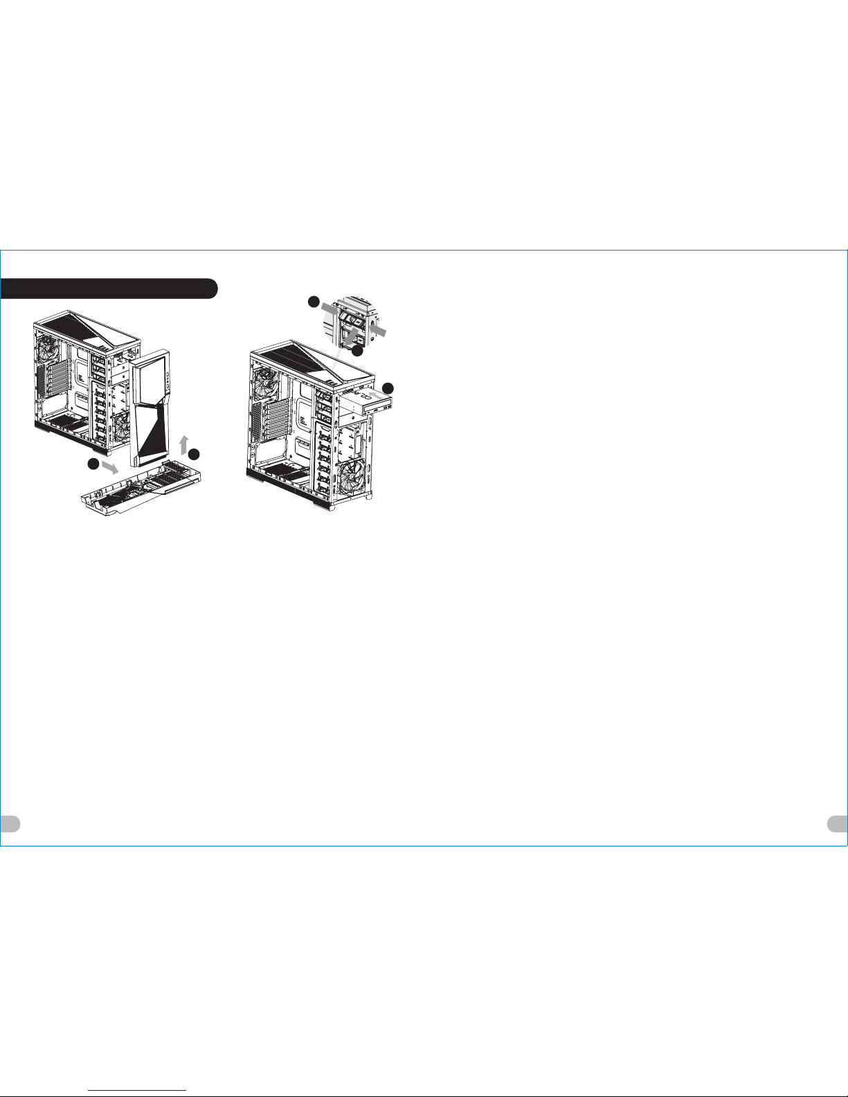
5.25” Drives Installation
English /
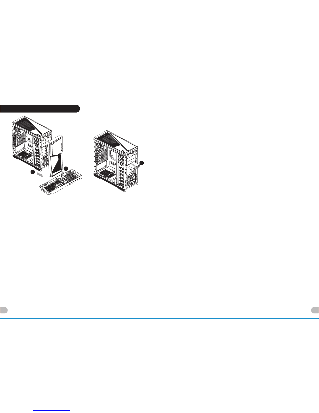
1. Pull the bottom of the front panel to
detach it from the chassis.
2. Remove the 5.25" drive bay plastic cover.
3. Remove the 5.25" drive bay metal cover.
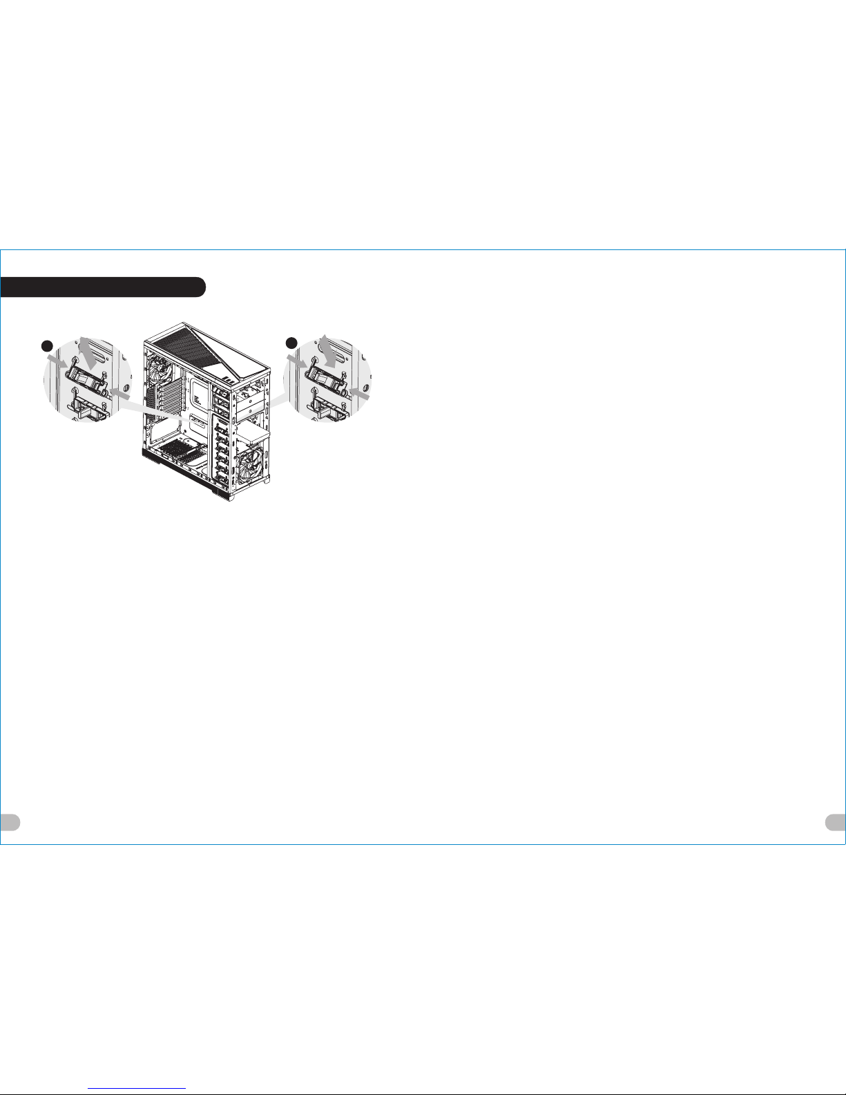
4. Push inward and upward to unlock the
tool-free clip on 5.25” cage.
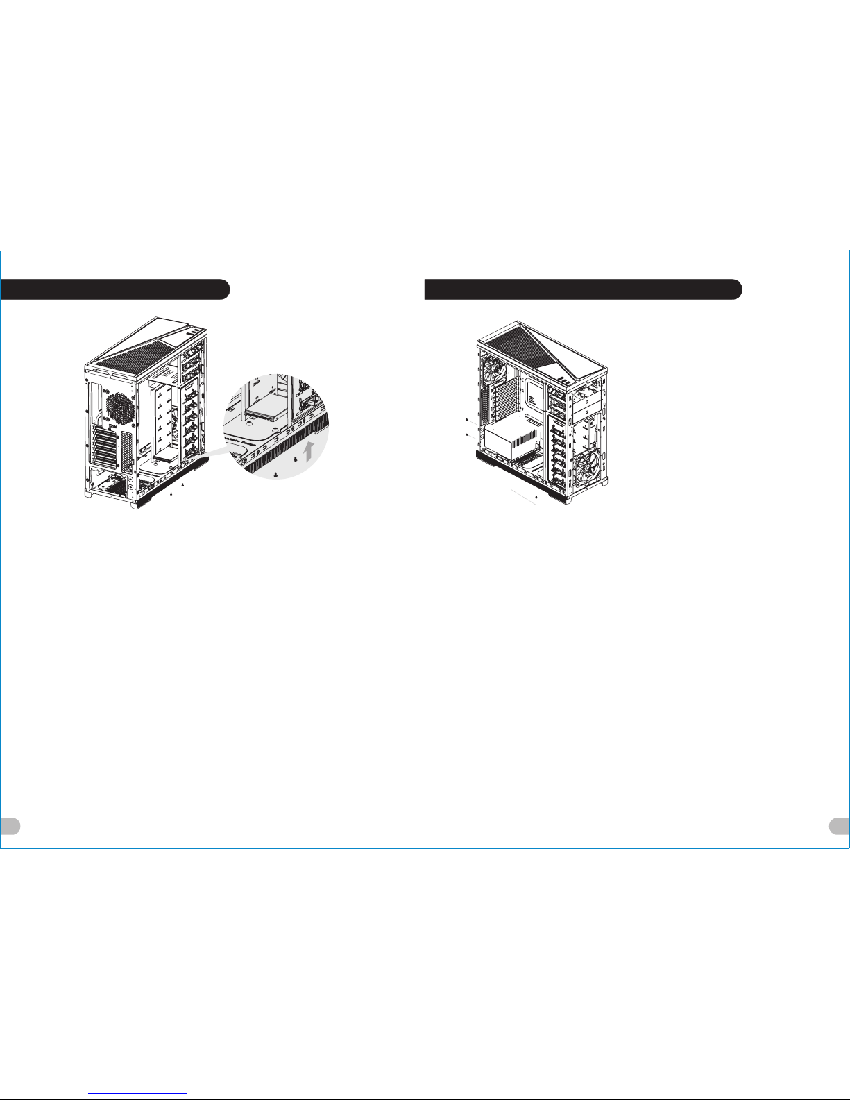
5. Insert the 5.25” device into the driver bay
and push inward and downward to lock
the tool-free clip.
Deutsch /
1. Ziehen Sie am unteren Rand der
Vorderseitentafel, um sie vom Gehäuse
zu entfernen.
2. Entfernen Sie die Plastikabdeckung des
5,25 Zoll Schachts.
3. Entfernen Sie die Metallabdeckung des
5,25 Zoll Schachts.
3. Drücken Sie einwärts und aufwärts, um
den Clip ohne Werkzeug auf dem 5,25
Zoll HDD-Käfig zu entsperren.
5. Führen Sie die 5,25 Zoll Einheit in den
Schacht ein und drücken Sie einwärts und
abwärts, um den werkzeuglosen Clip zu
befestigen.
Français /
1. Tirez sur le bas du panneau avant pour le
démonter du châssis.
2. Retirez le couvercle en plastique de la baie 5.25"
3. Retirez le couvercle en métal de la baie pour
lecteur 5.25"
4. Poussez vers l’intérieur et vers le haut pour
déverrouiller le clip sans outil sur la cage à
disque dur 5.25”
5. Insérez le périphérique 5.25” dans la baie pour
lecteur et poussez vers l’intérieur et vers le bas
pour verrouiller le clip sans outil.
Español /
1. Tire de la parte inferior del panel frontal para
separarlo del chasis.
2. Extraiga la cubierta de plástico de la bahía de
unidad de 5,25 pulgadas.
3. Extraiga la cubierta metálica de la bahía de
unidad de 5,25 pulgadas.
4. Empuje hacia dentro y hacia arriba para abrir el
sujetador sin herramientas del cajón del HDD de
5,25 pulgadas.
5. Inserte el dispositivo de 5,25 pulgadas en la bahía
de unidad y empuje hacia dentro y hacia abajo para
cerrar el sujetador sin herramientas.
1
2
4
5
3