Thermaltake Soprano VO9000 Series User manual

лчиттничюнльтцию.
глтчн.Бзвыдны
www.sotmarket.ru
дбняинфмциятв,
тзывы,бзыиы
Инструкция
New Soprano VO900M1N2N
Thermaltake
Перейти в карточку товара
8 800 775 98 98

© 2012 Thermaltake Technology Co., Ltd. All Rights Reserved. 2012.08
All other registered trademarks belong to their respective companies.www.thermaltake.comUser's ManualBenutzerhandbuchMode demploiManual del usuarioManuale dellutenteManual do Utilizador kullanc elkitab(EEE Yönetmeliine Uygundur)Tested To ComplyWith FCC StandardsFOR HOME OR OFFICE USEVO9000 SeriesJust Mute it

Chapter 1. Product IntroductionChapter 2. Installation GuideChapter 3. Leads InstallationCase LED ConnectionUSB Connection 2.0USB Connection 3.0Audio Connection2.02.12.22.32.42.52.62.72.81.11.21.33.13.23.33.402020305060708101113181920-2520-2520-2520-25Contents12SpecificationFigureParts NameQ'tyUsed forAccessorySpecificationAccessoryWarning and NoticeChapter 4. OtherToughpower / TR2 / Litepower power supply series (Optional)4.026Case TypeMid TowerChassis Dimension(H*W*D)460 x 220 x 510 (18 x 8.7 x 20 inch)Net Weight8.3 kg/18.3lbMaterialSECCCooling System Drive Bays-Accessible-HDD DockingExpansion Slots7Motherboards9.6 x 9.6 (Micro ATX), 12 x 9.6 (ATX) I/O PortsPSUStandard PS2 PSULCS UpgradableFront (intake) : 200 x 200 x 20 mm Blue LED fan x 1 (600rpm, 13dBA)Rear (exhaust) : 120 x 120 x 25 mm Turbo fan (1000rpm,16dBA)Bottom (Intake) : (optional) 120 x 120 x 25 mmUSB 3.0 x 2, USB 2.0 x 2, HD Audio x 1Supports 1/23/81/4 water tube4 x 5.25", 1 x 3.5"5 x 3.5" or 2.5"1 x 3.5" or 2.5"Side Panel DisassemblyMotherboard InstallationPSU Installation5.25" Device InstallationExternal 3.5 Device Installation3.5 & 2.5 HDD InstallationPCI Card InstallationKeyboard & Mouse Security Lock Usage6#32 Screw6#32 ScrewM3 Screw6#32 HDD Screw4142816Power SupplyMotherboardODD & 2.5" HDD3.5" HDD-HiddenCPU cooler height limitation: 175mmVGA length limitation: 315mmOtherModelSoprano SeriesMovable tieNut setterBuzzerCable ManagmentMotherboard InstallationMotherboard Alarm5116#32 Stand-off1MotherboardHDD Docking Station

<175 mm<315 mm
CPU Cooler Height LimitationVGA (Add-on card) Length Limitation34Warning and NoticeWarning!!- Height limit for the CPU heatsink: The height limit for the CPU heatsink is 175 mm (6.9 inches).- Length limit for the VGA (graphics card): The length limit for the VGA (graphics card) is 315 mm (12.4 inches).Warnung!!- Höhenbeschränkung für CPU-Kühler: Die Höhenbeschränkung für den CPU-Kühler liegt bei 175 mm (6.9 Zoll).- Längenbeschränkung für die VGA (Grafikkarte): Die Längenbeschränkung für die VGA (Grafikkarte) beträgt 315 mm (12.4 Zoll).Avertissement !- Hauteur limite du dissipateur thermique du processeur : La hauteur limite du dissipateur thermique du processeur est de 175 mm (6.9 pouces).- Longueur limite de la carte VGA (carte graphique) : La longueur limite de la carte VGA (carte graphique) est de 315 mm (12.4 pouces).Precaución- Límite de altura para el disipador de calor de la CPU: El límite de altura para el disipador de calor de la CPU es de 175 mm (6.9 pulgadas).- Límite de longitud para la tarjeta gráfica (VGA): El límite de longitud para la tarjeta gráfica (VGA) en de 315 mm (12.4 pulgadas).Attenzione!- Limite di altezza per il dissipatore di calore della CPU: Il limite di altezza per il dissipatore di calore della CPU è 175 mm (6.9").- Limite di lunghezza per la VGA (schede grafiche): Il limite di lunghezza per la VGA (scheda grafica) è 315 mm (12.4"). Atenção!!- Limite de altura para o dissipador do CPU: O limite de altura para o dissipador do CPU é 175 mm (6.9 polegadas).- Limite de comprimento para VGA (placa gráfica): O limite de comprimento para VGA (placa gráfica) é 315 mm (12.4 polegadas).- CPU: CPU175mm ( 6.9 )- VGA(): VGA()315mm (12.4 )- CPU CPU175mm6.9- VGA VGA315mm12.4- CPU: CPU175 mm- VGA: VGA315 mm!- . 175 (6.9 ).- VGA ( ). VGA ( ) 315 (12.4 ).Uyar!!- CPU s alcs için yükseklik snr: CPU s alcs için yükseklik snr 175 mmdir (6.9 inç).- VGA (grafik kart) için uzunluk snr: VGA (grafik kart) için uzunluk snr 315 mmdir (12.4 inç).!!- CPU: CPU 175 . (6.9 )- VGA (): VGA () 315 . (12.4 )

Side Panel Disassembly56English /Remove the screws on the back of the chassis, and open the side panel.Deutsch /Entfernen Sie die Schrauben auf der Rückseite des Gehäuses und öffnen Sie das Seitenteil.Français /Enlevez les vis à larrière du châssis et ouvrez le panneau latéral.Español /Extraiga los tornillos de la parte posterior de la caja y abra el panel lateral.Italiano /Rimuovere le viti sulla parte posteriore dello chassis e aprire il pannello laterale.Português/Remova os parafusos na parte de trás da caixa e abra o painel lateral. / / / . /Türkçe /Kasann arkasndaki vidalar çkarn ve yan paneli açn. / Motherboard InstallationEnglish /1. Lay down the chassis.2. Install the motherboard in proper location and secure it with screws.Deutsch /1. Legen Sie das Gehäuse auf die Seite.2. Installieren Sie die Hauptplatine in ihrer vorgesehenen Position und sichern Sie sie mit Schrauben. Français /1. Posez à plat le châssis.2. Installez la carte mère dans l'endroit approprié et sécurisez-la avec des vis.Español /1. Tumbe el chasis.2. Instale la placa madre en la ubicación adecuada y asegúrela con tornillos.Italiano /1. Poggiare lo chassis.2. Installare la scheda madre nella posizione appropriata e fissarla con le viti.Português/1. Deixe a caixa.2. Instale a motherboard no local adequado e aparafuse. /1. 2. /1. 2. /1. . 2. . /1. 2. Türkçe /1. Kasay yan yatrn.2. Ana kart uygun konuma takn ve vidalarla sabitleyin. /1. 2.

78English /Place the power supply in proper location and secure it with screws.Deutsch /Installieren Sie das Netzteil an seiner Position und sichern Sie es mit Schrauben. Français /Mettez l'alimentation dans le bon endroit et sécurisez-la avec des vis.Español /Coloque el suministro de alimentación en el lugar adecuado y asegúrelo con tornillos. Italiano /Posizionare l'alimentatore in modo appropriato e fissarlo utilizzando le viti.Português/Coloque a fonte de alimentação na devida localização e aparafuse. / / / . /Türkçe /Güç kaynan uygun konuma yerletirin ve vidalarla sabitleyin. /PSU Installation5.25" Device InstallationEnglish /1. Remove the 5.25 drive bay cover.2. Slide the 5.25 device into the drive bay to lock the device.Note: Press the 5.25 tool-free mechanism to unlock the device.Deutsch /1. Entfernen Sie die Abdeckung des 5,25 Zoll Laufwerksschachts.2. Schieben Sie the 5,25 Zoll Einheit in den Laufwerksschacht, um die Einheit zu sperren.Anmerkung: Drücken Sie den 5,25 Zoll werkzeuglosen Mechanismus, um die Einheit zu verriegeln.Français /1. Enlevez le couvercle de la baie de lecteur de 5,25".2. Faites glisser le périphérique de 5,25" dans la baie de lecteur.Remarque : Appuyez sur le mécanisme sans outil de 5,25" pour déverrouiller le périphérique.Español /1. Extraiga la tapa del hueco de la unidad de 5,25".2. Meta el dispositivo de 5,25 en el hueco de la unidad para cerrar el dispositivo.Nota: Presione el mecanismo libre de herramienta de 5,25 para abrir el dispositivo.Italiano /1. Rimuovere il coperchio dellalloggiamento vano unità da 5,25.2. Fare scorrere il dispositivo da 5,25 nellalloggiamento dellunità per bloccare il dispositivo.Nota: Premere il meccanismo tool-free da 5,25 per sbloccare il dispositivo.Português/1. Remova a cobertura da baía da unidade de 5,25".2. Deslize o dispositivo de 5,25" para a baía da unidade, para bloquear o dispositivo.Nota: Pressione o mecanismo de 5,25" sem utilizar ferramentas para desbloquear o dispositivo.2

910English /1. Remove the 3.5 drive bay cover. 2. Insert the device into the 3.5 drive bay.3. Insert the 3.5 HDD and tighten it with the screws. Deutsch /1. Entfernen Sie die Abdeckung des 3,5 Zoll Schachts.2. Fügen Sie die Einheit in den 3,5 Zoll Laufwerksschacht ein.3. Führen Sie die 3,5 Zoll HDD ein und befestigen Sie sie mit den Schrauben. Français /1. Retirez le couvercle de la baie de lecteur 3.5"2. Insérez le périphérique 3.5" dans la baie pour lecteur.3. Insérez le disque dur de 3,5" et sécurisez-le avec les vis. Español /1. Extraiga la cubierta de la bahía de unidad de 3,5 pulgadas.2. Coloque el dispositivo de 3,5 pulgadas en la bahía de unidad.3. Inserte el disco duro de 3,5 y apriételo con los tornillos. External 3.5 Device InstallationItaliano /1. Rimuovere il coperchio dell'alloggiamento dell'unità da 3,5 pollici2. Inserire il dispositivo nel vano dell'unità da 3,5.3. Inserire il dispositivo HDD da 3,5 e fissarlo con le viti. Português/1. Remova a cobertura da baía da unidade de 3,5.2. Insira o dispositivo na baía da unidade de 3,5.3. Insira o disco rígido de 3,5" e aparafuse. /1. 3.5" 2. 3.5 3. 3.5 HDD /1. 3,5 - .2. 3,5- .3. 3,5- . /1. 3.5 2. 3.5 3. 3.5Türkçe /1. 3.5 sürücü bölmesi kapan çkarn.2. Aygt, 3.5 sürücü bölmesinin içine yerletirin.3. 3,5 HDDyi yerletirin ve vidalarla sabitleyin. /1. 3.5 2. 3.53. HDD 3.5 /1. 3.52. 3. 3.5 /1. 5.252. 5.25: 5.255.255.25 /1. 5.252. 5.25: 5.255.255.25 /1. 5.252. 5.25: 5.25 /1. 5,25- .2. 5,25- .. 5,25- , .Türkçe /1. 5,25" sürücü bölmesi kapan çkarn.2. 5,25 aygtn kilitlemek için sürücü bölmesinin içine doru kaydrn.Not: Aygtn kilidini açmak için 5,25 araçsz mekanizmay bastrn.1. 5.25" 2. 5.25" : 5.25" /2

113.5 & 2.5 HDD Installation122 3.5" HDD2.5" HDDEnglish /Italiano /1. Pull the HDD tray out. 1. Estrarre il vano HDD.2. Place the 2.5 or 3.5 hard drive on the tray 2. Posizionare il disco fisso da 2,5 o 3,5 nel and secure it with screws.vano e fissarlo con le viti.3. Slide the HDD tray back to the HDD cage. 3. Fare scorrere lHDD indietro verso la struttura a gabbia HDD.Deutsch /Português /1. Ziehen Sie den HD-Schacht heraus.1. Puxe a bandeja do disco rígido para fora.2. Montieren Sie die 2,5 oder 3,5 Zoll Festplatte im Schacht und sichern Sie sie mit Schrauben.2. Coloque o disco rígido de 2,5 ou 3,5 na bandeja e fixe com parafusos.3. Schieben Sie den Schacht wieder in den Festplattenkäfig.3. Deslize a bandeja do disco rígido de volta para a caixa do disco rígido.Français / /1. Enlevez le boîtier du disque dur.1. 2. Placez le disque dur de 2,5 ou de 3,5 dans le boîtier et fixez-le avec des vis.2. 2.53.53. Refaites glisser le boîtier du disque dur dans la cage de disques durs.3. Español / /1. Extraiga la bandeja del disco duro.1. 2. Coloque el disco duro de 25 ó 3'5 en la 2. 2.53.5bandeja y fíjelo con los tornillos. 3. Vuelva a meter la bandeja del disco duro en su 3. hueco. /1.HDD2..5HDDSSD .5HDD3. HDDHDD /1. .2. 2,5- 3,5- .3. .Türkçe /1. HDD tepsisini dar çekin.2. 2,5 veya 3,5 sabit disk sürücüsünü tepsinin üzerine yerletirin ve vidalarla sabitleyin.3. HDD tepsisini HDD kafesine geri yerletirin. /1. HDD 2. 2.5 3.5 3. HDD HDDNote:

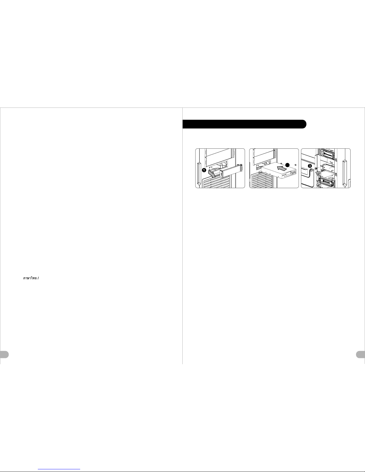
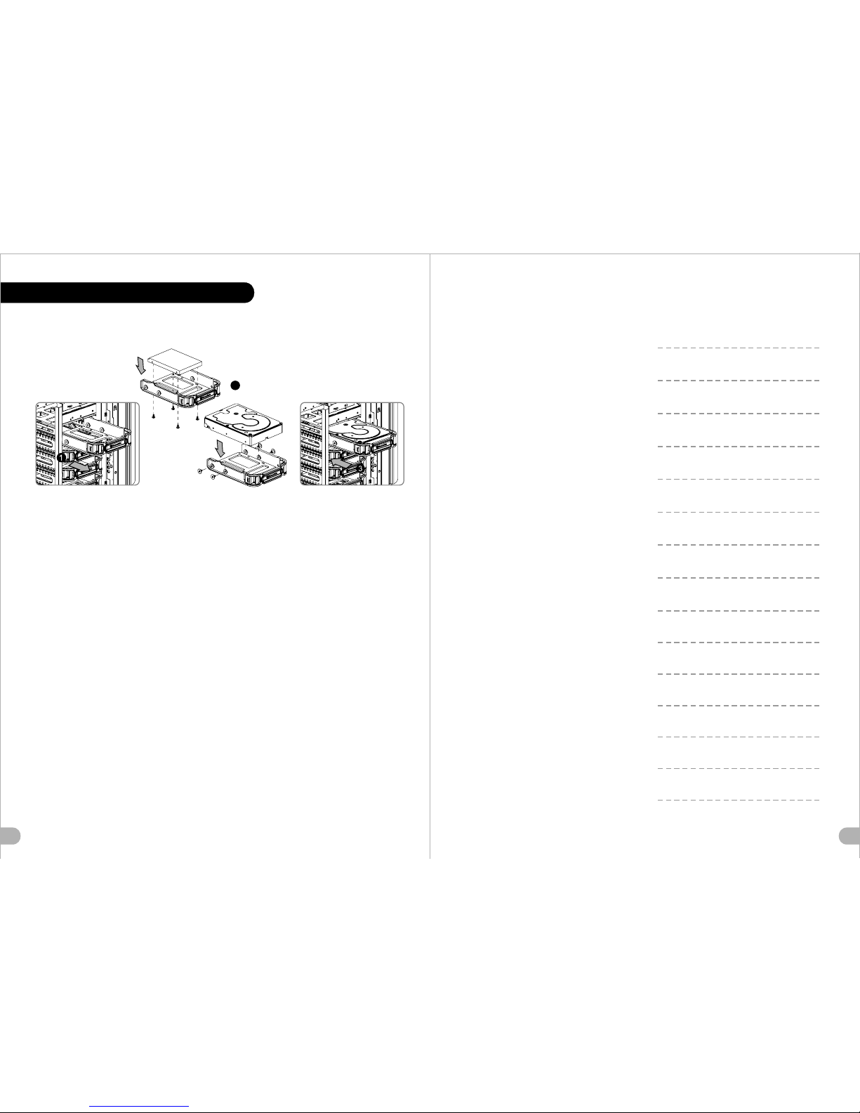
1314HDD Docking StationEnglish /The top HDD Docking slot is embedded to enable ultra fast transfer (up to 6.0Gbps) of large data to a SATA hard disk without having to use an external storage enclosure. To ensure proper operation, please make sure the following settings are correct:- Ensure all required drivers are installed for your motherboard or SATA controller card.- Connect the SATA cable to an available SATA connector on the motherboard or SATA controller card.- Connect the power cable to power supply.- Ensure AHCI (Advanced Host Controller Interface) is enabled on your motherboard or SATA controller card. The AHCI enables for hotswap capability of the SATA hard drives without having to turn off the computer prior to connecting or disconnecting of the hard drive. Please follow instruction provided by your motherboard or SATA controller card to enable the AHCI function.If you are using a brand new hard drive, the hard drive will need to be initialized (formatted) before it is accessible. For more information on how to initialize (format) a new hard drive, please refer to the hard drive user manual or visit System running on Windows 7: http://www.thermaltakeusa.com/Faq.aspx?ID=1143System running on Windows Vista: http://www.thermaltakeusa.com/Faq.aspx?ID=1079System running on Windows XP: http://www.thermaltakeusa.com/Faq.aspx?ID=1073Deutsch /Der obere Einführungsschlitz der HDD-Dockingstation ist eingelassen, um einen ultraschnellen Transfer (bis zu 6,0 GB/s) von umfangreichen Daten zur SATA-Festplatte zu ermögichen, ohne dafür ein externes Gehäuse verwenden zu müssen. Um einen ordnungsgemäßen Betrieb zu gewährleisten, stellen Sie bitte sicher, dass die folgenden Einstellungen richtig sind:- Stellen Sie sicher, dass alle erforderlichen Treiber für Ihr Mainboard oder SATA Controller-Karte installiert sind. - Verbinden Sie das SATA-Kabel mit einen freien SATA-Anschluss auf dem Mainboard oder der SATA Controller-Karte. - Verbinden Sie das Stromkabel mit dem Netzteil.- Stellen Sie sicher, dass AHCI (Advanced Host Controller Interface) auf dem Motherboard oder der SATA-Controller-Karte aktiviert ist. AHCI ermöglicht die "HotSwap"-Funktion der SATA-Festplatten, ohne dass Sie den Computer ausschalten müssen, bevor Sie die Festplatte anschließen oder entfernen. Bitte folgen Sie den Anweisungen Ihres Motherboards oder der SATA-Controller-Karte, um die AHCI-Funktion zu aktivieren. Wenn Sie eine neue Festplatte benutzen, muss die Festplatte initialisiert werden (formatiert), bevor sie nutzbar ist. Weitere Informationen darüber, wie man eine neue Festplatte formatiert, entnehmen Sie bitte dem Benutzerhandbuch zur Festplatte oder besuchen Sie System läuft unter Windows 7: http://www.thermaltakeusa.com/Faq.aspx?ID=1143System läuft unter Windows Vista:http://www.thermaltakeusa.com/Faq.aspx?ID=1079System läuft unter Windows XP: http://www.thermaltakeusa.com/Faq.aspx?ID=1073Français /La station daccueil verticale de disque dur est intégrée pour permettre le transfert ultra rapide (jusquà 6,0 Gbits/s) de données volumineuses vers un disque dur SATA sans devoir utiliser un boîtier de stockage externe. Pour assurer un bon fonctionnement, veuillez vérifier la justesse des paramètres suivants :- Vérifiez que tous les pilotes requis soient installés pour votre carte mère ou votre carte contrôleur SATA.- Connectez le câble SATA à un connecteur SATA disponible sur la carte mère ou la carte contrôleur SATA.- Connectez le cordon dalimentation à lalimentation.- Vérifiez que le mode AHCI (Advanced Host Controller Interface) soit activé sur votre carte mère ou votre carte contrôleur SATA. Le mode AHCI permet « léchange à chaud » des disques durs SATA sans devoir éteindre l'ordinateur avant de connecter ou de débrancher le disque dur. Veuillez suivre les directives de votre carte mère ou de votre carte contrôleur SATA pour activer la fonction AHCI.Si vous utilisez un disque dur neuf, il devra être initialisé (formaté) avant de devenir accessible. Pour plus d'informations sur comment initialiser (formater) un nouveau disque dur, veuillez vous reporter au manuel de l'utilisateur du disque dur ou visitez Pour un système qui exécute Windows 7 : http://www.thermaltakeusa.com/Faq.aspx?ID=1143Pour un système qui exécute Windows Vista : http://www.thermaltakeusa.com/Faq.aspx?ID=1079Pour un système qui exécute Windows XP : http://www.thermaltakeusa.com/Faq.aspx?ID=1073Español /La ranura de acoplamiento de disco duro principal se aloja para facilitar la transferencia ultra rápida (hasta 6,0 Gbps) de muchos datos a un disco duro SATA sin tener que utilizar una cubierta de almacenamiento externa. Para garantizar un funcionamiento adecuado, asegúrese de que los siguientes ajustes son correctos:- Asegúrese de que están instalados todos los controladores necesarios para la placa base o la tarjeta controladora SATA.- Conecte el cable SATA a un conector SATA disponible de la placa base o la tarjeta controladora SATA.- Conecte el cable de alimentación a la fuente de energía.- Asegúrese de que AHCI (Interfaz de controlador host avanzada) está activada en la placa base o la tarjeta controladora SATA. La AHCI activa la función "intercambio en caliente de los discos duros SATA sin tener que apagar el equipo antes de conectar o desconectar el disco duro. Siga las instrucciones proporcionadas por la placa base o la tarjeta controladora SATA para activar la función AHCI.Si utiliza un disco duro nuevo, éste necesitará inicializarse (formatearse) antes de acceder a él. Para obtener más información sobre cómo inicializar (formatear) un disco duro nuevo, consulte el manual del usuario del disco duro o visite Sistema ejecutado en Windows 7: http://www.thermaltakeusa.com/Faq.aspx?ID=1143Sistema ejecutado en Windows Vista:http://www.thermaltakeusa.com/Faq.aspx?ID=1079Sistema ejecutado en Windows XP: http://www.thermaltakeusa.com/Faq.aspx?ID=1143Italiano /Lo slot HDD Docking superiore è integrato e consente un trasferimento ultraveloce (fino a 6,0 Gbps) di grandi quantità di dati in un disco rigido SATA senza dover usare alcun dispositivo di archiviazione interno. Per garantire il corretto funzionamento, verificare che le seguenti impostazioni siano corrette:- Verificare che siano installati tutti i driver richiesti per la scheda madre o la scheda del controller SATA.- Collegare il cavo SATA ad un connettore SATA disponibile nella scheda madre o nella scheda del controller SATA.- Collegare il cavo di alimentazione allalimentatore.- Verificare che linterfaccia AHCI (Advanced Host Controller Interface) sia abilitata sulla scheda madre o sulla scheda del controller SATA. Linterfaccia AHCI consente la funzionalità hotswap delle unità rigide SATA senza dovere spegnere il computer prima di collegare o scollegare il disco rigido. Seguire le istruzioni fornite per la scheda madre o la scheda del controller SATA per abilitare la funzione AHCI.Se si utilizza il disco rigido di una nuova marca, sarà necessario inizializzarlo (formattarlo) per renderlo accessibile. Per ulteriori informazioni sull'inizializzazione (formattazione) di un nuovo disco rigido, consultare il manuale utente del disco rigido oppure verificareil sistema in esecuzione su Windows 7: http://www.thermaltakeusa.com/Faq.aspx?ID=1143Sistema in esecuzione su Windows Vista: http://www.thermaltakeusa.com/Faq.aspx?ID=1079Sistema in esecuzione su Windows XP: http://www.thermaltakeusa.com/Faq.aspx?ID=1073

1516Português/O topo da ranhura da Estação base do disco rígido está integrado para permitir uma transferência ultra rápida (até 6.0Gbps) de grandes dados para um disco rígido SATA sem utilizar um disco de armazenamento externo. Para garantir o funcionamento correcto, certifique-se que as seguintes definições estão correctas:- Certifique-se que todos os drivers necessários estão instalados na sua motherboard ou placa de controlador SATA.- Ligue o cabo SATA a um conector SATA disponível na motherboard ou na placa de controlador SATA.- Ligue o cabo de alimentação à fonte de alimentação.- Certifique-se que AHCI (Advanced Host Controller Interface) está activado na sua motherboard ou placa de controlador SATA. O AHCI permite a capacidade "hotswap" dos discos rígidos SATA sem ter de desligar o computador antes de ligar ou desligar o disco rígido. Siga as instruções fornecidas pela sua motherboard ou pela placa de controlador SATA para activar a função AHCI.Se estiver a utilizar um disco rígido novo pela primeira vez, o disco rígido terá de ser iniciado (formatado) antes de estar acessível. Para mais informações sobre como iniciar (formatar) um disco rígido novo, consulte o manual de utilizador do disco rígido ou visite Sistema a funcionar no Windows 7: http://www.thermaltakeusa.com/Faq.aspx?ID=1143Sistema a funcionar no Windows Vista:http://www.thermaltakeusa.com/Faq.aspx?ID=1079Sistema a funcionar no Windows XP: http://www.thermaltakeusa.com/Faq.aspx?ID=1073 / SATA ( 6.0Gbps)- SATA - SATA SATA SATA - - SATA AHCI AHCI SATA SATA AHCI Windows 7 http://www.thermaltakeusa.com/Faq.aspx?ID=1143Windows Vista http://www.thermaltakeusa.com/Faq.aspx?ID=1079Windows XP http://www.thermaltakeusa.com/Faq.aspx?ID=1073 / SATA ( 6.0Gbps)- SATA - SATA SATA SATA - - SATA AHCI AHCI SATA SATA AHCI Windows 7 http://www.thermaltakeusa.com/Faq.aspx?ID=1143Windows Vista http://www.thermaltakeusa.com/Faq.aspx?ID=1079Windows XP http://www.thermaltakeusa.com/Faq.aspx?ID=1073 /HDDSATA6.0Gbps- SATA -SATASATASATA --AHCI () SATA AHCISATA AHCISATA WebWindows 7:http://www.thermaltakeusa.com/Faq.aspx?ID=1143Windows Vista:http://www.thermaltakeusa.com/Faq.aspx?ID=1079Windows XP:http://www.thermaltakeusa.com/Faq.aspx?ID=1073 / - ( 6,0 /) SATA . :- , SATA.- SATA SATA SATA.- .- , SATA AHCI (Advanced Host Controller Interface ). AHCI «» SATA . AHCI , SATA. , , (). () . -: Windows 7: http://www.thermaltakeusa.com/Faq.aspx?ID=1143 Windows Vista: http://www.thermaltakeusa.com/Faq.aspx?ID=1079 Windows XP: http://www.thermaltakeusa.com/Faq.aspx?ID=1073

Türkçe /Üst HDD Balant yuvas, büyük miktarlarda verilerin d depolama kasas kullanma zorunluluu olmadan bir SATA sabit diskine ultra hzl aktarmn (en fazla 6,0 Gb/s) salamak için yerleik olarak tasarlanmtr. Sorunsuz çalma için lütfen aadaki ayarlarn doruluundan emin olun:- Ana kartnz veya SATA denetleyici kartnz için gerekli tüm sürücülerin yüklü olduundan emin olun.- SATA kablosunu, ana kart veya SATA denetleyici kart üzerindeki kullanlabilir bir SATA konektörüne balayn.- Güç kablosunu güç kaynana balayn.- Ana kartta veya SATA denetleyici kartnda AHCInin (Gelimi Ana Bilgisayar Denetleyici Arabirimi) etkinletirildiinden emin olun. AHCI, sabit disk sürücüsünü balamadan veya sürücünün balantsn kesmeden önce bilgisayar kapatmanza gerek brakmayan, SATA sabit disk sürücülerine çalrken deitirilebilme yetenei salar. AHCI ilevini etkinletirmek için ana kartnz veya SATA denetleyici kartnz tarafndan salanan aadaki yönergeyi izleyin.Daha önce hiç kullanlmam bir sabit disk sürücüsü kullanyorsanz, sabit disk sürücüsünün eriilebilir olmadan önce balatlmas (biçimlendirilmesi) gerekir. Yeni bir sabit disk sürücüsünün nasl balatlaca (biçimlendirilecei) konusunda daha fazla bilgi için sabit disk sürücüsü kullanc klavuzuna bakn veya aadaki adresleri ziyaret edin: Windows 7 üzerinde çalan sistem: http://www.thermaltakeusa.com/Faq.aspx?ID=1143Windows Vista üzerinde çalan sistem: http://www.thermaltakeusa.com/Faq.aspx?ID=1079Windows XP üzerinde çalan sistem: http://www.thermaltakeusa.com/Faq.aspx?ID=1073 SATA ( 6.0 Gbps) :- SATA - SATA SATA SATA - - AHCI (Advanced Host Controller Interface) SATA AHCI "Hotswap" ( ) SATA SATA AHCI () () Windows 7: http://www.thermaltakeusa.com/Faq.aspx?ID=1143 Windows Vista:http://www.thermaltakeusa.com/Faq.aspx?ID=1079 Windows XP: http://www.thermaltakeusa.com/Faq.aspx?ID=1073 /PCI Card InstallationPortuguês /1. Desaperte os parafusos com a chave de fendas. 2. Instale a placa PCI no local adequado e aparafuse.English /1. Loosen the screws with a screwdriver.2. Install the PCI card in proper location and secure it with screws.Deutsche /1. Lösen Sie die Schrauben mit einem Schraubendreher.2. Installieren Sie die PCI-Card in der vorgesehenen Position und sichern Sie sie mit Schrauben.Français /1. Desserrez les vis à laide dun tournevis.2. Installez la carte PCI dans l'endroit approprié et fixez-la avec des vis.Español /1. Afloje los tornillos con un destornillador.2. Instale la tarjeta PCI en la ubicación adecuada y asegúrela con tornillos.Italiano /1. Allentare le viti con un cacciavite.2. Installare la scheda PCI nella posizione appropriata e fissarla con le viti. /1. 2. PCI /1. .2. /1. 2. PCI /1. .2. Türkçe /1. Vidalar, bir tornavida ile gevetin.2. PCI kartn uygun konuma takn ve vidalarla sabitleyin. /1. .2. PCI .1718

1920Keyboard & Mouse Security Lock UsageEnglish /Deutsch /Français /Español /Italiano /Português/ Passe os cabos do teclado ou do rato através do "Bloqueio de Segurança do Teclado e Rato" e fixe na parte traseira do painel no interior do chassis, com parafusos.Place the keyboard or mouse cables through the Keyboard & Mouse Security Lock then secure it back to the back panel from inside of the chassis with screw. Führen Sie die Kabel durch die Einheit Tastatur- & Maussperren und sichern Sie sie dann wieder an der Rückwand innerhalb des Gehäuses mit den Schrauben.Mettez les câbles du clavier ou de la souris à travers le verrou de sécurité de clavier & souris puis sécurisez-les sur le panneau arrière à l'intérieur du châssis avec des vis.Mettez les câbles du clavier ou de la souris à travers le verrou de sécurité de clavier & souris puis sécurisez-les sur le panneau arrière à l'intérieur du châssis avec des vis.Posizionare i cavi della tastiera o del mouse sulla tastiera e il blocco di sicurezza del mouse, quindi fissarli sul pannello posteriore dallinterno dello chassis con la relativa vite. / / / / / / /Türkçe / / . . Klavye veya fare kablolarn Klavye ve Fare Güvenlik Kilidi üzerinden yerletirin ve daha sonra, güvenlik kilidini kasann iç tarafndan arka panele yeniden vidalayn. Leads Installation GuideLeads Installation GuideCase LED Connection / On the front of the case, you can find some LEDs and switch leads. Please consult your user manual of your motherboard manufacturer, then connect these leads to the panel header on the motherboard.USB 2.0 Connection / Please consult your motherboard manual to find out the section of USB connection.USB 3.0 connection / 1. Make sure your motherboard supports internal USB 3.0 connection.2. Connect the USB 3.0 cable to the available USB 3.0 port on your computer.Audio Connection / Please refer to the following illustration of Audio connector and your motherboard user manual. Please select the motherboard which used AC97 or HD Audio(Azalia),(be aware of that your audio supports AC97 or HD Audio (Azalia)) or it will damage your device(s).Anschlüsse herstellenGehäuse-LED-Verbindungen / Auf der Gehäusevorderseite finden Sie einige LEDs und Verbindungen. Bitte nehmen Sie die Gebrauchsanweisung Ihres Motherboard Herstellers zur Hilfe und schließen Sie diese Verbindungen an die Panel Header Belegung des Motherboards an.USB 2.0 Anschluss / Bitte nehmen Sie die Gebrauchsanweisung Ihres Motherboards zur Hilfe und lesen Sie unter dem Kapitel USB Anschlüsse nach.USB 3.0 Anschluss / 1. Stellen Sie sicher, dass Ihre Hauptplatine den internen USB 3.0 Anschluss unterstützt.2. Verbinden Sie das USB 3.0 Kabel mit dem USB 3.0 Port auf Ihrem Computer.Audio Anschlüsse / Bitte beachten Sie die folgende Abbildung der Audio Anschlüsse und die Anweisung in der Gebrauchsanweisung Ihres Motherboards. Bitte wählen Sie das Motherboard, das AC97 oder HD Audio(Azalia) verwendet, (achten Sie darauf, dass Ihr Audio AC97 bzw. HD Audio (Azalia unterstützt)). Andernfalls entstehen schwere Schäden an Ihrem(n) Gerät(en)!!!AUDIO AC'97 FunctionGROUNDL-RETR-RETNCBROWNREDMIC INMIC POWERKEYBLUENCBLUEL-OUTYELLOWR-OUTBLACKYELLOWPRESENCE#BLACKSENSE1_RETURNAUD GNDSENSE2_RETURNYELLOWBROWNREDPORT1 RPORT2 RPORT1 LBLUEPORT2 LSENSE_SENDKEYPURPLEGREENORANGEBLACKAUDIO AZALIA Function

2122Guide d'installation des filsConnexion des voyants du boîtier / Sur la face avant du boîtier, vous trouverez plusieurs voyants et les fils des boutons. S'il vous plaît consultez le guide d'utilisateur du fabricant de votre carte mère, puis connectez ces fils aux onnecteurs sur la carte mère.Connexion USB 2.0 / S'il vous plaît consultez le manuel de votre carte mère à la section "Connexion USB". Connexion USB 3.0 /1. Vérifiez que votre carte mère prend en charge une connexion USB 3.0 interne.2. Connectez le câble USB 3.0 au port USB 3.0 disponible sur votre ordinateur.Connexion Audio / S'il vous plaît référez vous à l'illustration suivante du connecteur audio et au guide de l'utilisateur de votre carte mère. S'il vous plaît sélectionnez une carte mère supportant AC'97 ou HD Audi (Azalia), (faites attention que votre audio supporte l'AC'97 ou HD Audio (Azalia)) sinon cela pourrait endommager votre matériel.Guía de Instalación de CablesConexión del LED de la caja / En la parte frontal de la caja, encontrará algunos LED y cables de interruptores. Consulte el manual del usuario del fabricante de la placa madre, a continuación conecte estos cables al conector de la placa madre.Conexión USB 2.0 / Consulte el manual de la placa madre para obtener más información sobre el apartado Conexión USB".Conexión USB 3.0 /1. Asegúrese de que la placa base admite conexión USB 3.0 interna.2. Conecte el cable USB 3.0 al puerto USB 3.0 disponible en el equipo.Conexión de Audio / Consulte la siguiente ilustración del conector de Audio y el manual del usuario de la placa madre. Seleccione la placa madre que utiliza AC97 o HD Audio (Azalia), (asegúrese de que su audio admite AC97 o HD Audio (Azalia)) si no, sus dispositivos resultarán dañados.AUDIO AC'97 FunctionGROUNDL-RETR-RETNCBROWNREDMIC INMIC POWERKEYBLUENCBLUEL-OUTYELLOWR-OUTBLACKYELLOWPRESENCE#BLACKSENSE1_RETURNAUD GNDSENSE2_RETURNYELLOWBROWNREDPORT1 RPORT2 RPORT1 LBLUEPORT2 LSENSE_SENDKEYPURPLEGREENORANGEBLACKAUDIO AZALIA FunctionGuida di installazione dei contattiConnessione del LED del case / Nella parte anteriore del case, sono presenti alcuni contatti per interruttori e LED. Consultare il manuale utente del produttore della scheda madre, quindi connettere i contatti alla parte superiore del pannello sulla scheda madre.Connessione USB 2.0 / Consultare il manuale per la scheda madre che comprende la sezione relative alla connessione USB.Connessione USB 3.0 /1. Accertarsi che la scheda madre supporti la connessione USB 3.0 interna.2. Collegare il cavo USB 3.0 alla porta USB 3.0 disponibile sul computer.Connessione Audio / Fare riferimento allillustrazione riportata di seguito del connettore Audio e al manuale utente per la scheda madre.Selezionare la scheda madre relativa a AC97 o HD Audio (Azalia) e considerare che il supporto audio è compatibile con AC97 o HD Audio (Azalia); in caso contrario, le periferiche potrebbero venire danneggiate.Guia de Instalação EléctricaLigação do LED da Caixa / Na parte dianteira da caixa pode encontrar alguns LEDs e fios eléctricos. Consulte o manual de utilizador do fabricante da sua motherboard e ligue os fios à parte superior do painel na motherboard.Ligação UBS 2.0 / Consulte o manual da sua motherboard para ver a secção de Ligação USB.Ligação USB 3.0 /1. Certifique-se que a sua motherboard suporta ligação USB 3.0 interna.2. Ligue o cabo USB 3.0 à porta USB 3.0 disponível no seu computador.Ligação Áudio / Consulte a imagem seguinte do conector Áudio e o manual de utilizador da sua motherboard.Seleccione a motherboard que utiliza AC97 ou HD Áudio(Azalia), (verifique se a sua placa de áudio suporta AC97 ou HD Áudio(Azalia)) ou irá danificar o(s) seu(s) dispositivo(s).PortuguêsAUDIO AC'97 FunctionGROUNDL-RETR-RETNCBROWNREDMIC INMIC POWERKEYBLUENCBLUEL-OUTYELLOWR-OUTBLACKYELLOWPRESENCE#BLACKSENSE1_RETURNAUD GNDSENSE2_RETURNYELLOWBROWNREDPORT1 RPORT2 RPORT1 LBLUEPORT2 LSENSE_SENDKEYPURPLEGREENORANGEBLACKAUDIO AZALIA Function

2423 / LEDPOWER Switch. USB 2.0 / USBUSB 3.0 / 1. USB 3.02. USB 3.0USB 3.0 / AC' 97HD(Azalia)LEDAUDIO AC'97 FunctionGROUNDL-RETR-RETNCBROWNREDMIC INMIC POWERKEYBLUENCBLUEL-OUTYELLOWR-OUTBLACKYELLOWPRESENCE#BLACKSENSE1_RETURNAUD GNDSENSE2_RETURNYELLOWBROWNREDPORT1 RPORT2 RPORT1 LBLUEPORT2 LSENSE_SENDKEYPURPLEGREENORANGEBLACKAUDIO AZALIA Function LED USB 2.0 / LED USB 2.0 / USBUSB 3.0 / 1. USB 3.02. USB 3.0USB 3.0 / AC97HD(Azalia)(AC97HD(Azalia))) LED LEDUSB 2.0 USB 3.0 / LEDPOWER Switch. USB 2.0 / USBUSB 3.0 /1. USB 3.02. USB 3.0USB3.0 / AC' 97HD(Azalia)LEDAUDIO AC'97 FunctionGROUNDL-RETR-RETNCBROWNREDMIC INMIC POWERKEYBLUENCBLUEL-OUTYELLOWR-OUTBLACKYELLOWPRESENCE#BLACKSENSE1_RETURNAUD GNDSENSE2_RETURNYELLOWBROWNREDPORT1 RPORT2 RPORT1 LBLUEPORT2 LSENSE_SENDKEYPURPLEGREENORANGEBLACKAUDIO AZALIA Function USB 2.0 / . . USB 2.0. « . USB 3.01. , USB 3.0.2. USB 3.0 USB 3.0 . / . . , AC'97 HD Audio (Azalia) (, AC'97 HD Audio (Azalia)). . / USB» /

2625Ara Kablo Kurulum KlavuzuKasa k balantsUSB 2.0 balantsSes BalantsAra Kablo Kurulum Klavuzu / Kasann ön ksmnda baz klar ve anahtar ara kablolar görebilirsiniz. Lütfen anakart üreticinizin salad kullanm klavuzuna bakn ve daha sonra, bu ara kablolar, anakart üzerindeki panel balant noktalarna balayn.USB 2.0 balants / Lütfen anakart klavuzunuzun USB balants bölümüne bakn.USB 3.0 Balants /1. Ana kartnzn dahili USB 3.0 balantsn desteklediinden emin olun.2. USB 3.0 kablosunu, bilgisayarnzdaki kullanlabilir USB 3.0 balant noktasna balayn.Ses Balants / Lütfen aadaki Ses konektörü resmine ve anakartnzn kullanm klavuzuna bakn. Lütfen AC97 veya HD Audio(Azalia) spesifikasyonunu kullanan bir anakart seçin (ses sisteminizin AC97 veya HD Audio (Azalia) spesifikasyonunu desteklediini unutmayn); aksi takdirde, aygt(lar)nz zarar görür.Kasa k balantsAUDIO AC'97 FunctionGROUNDL-RETR-RETNCBROWNREDMIC INMIC POWERKEYBLUENCBLUEL-OUTYELLOWR-OUTBLACKYELLOWPRESENCE#BLACKSENSE1_RETURNAUD GNDSENSE2_RETURNYELLOWBROWNREDPORT1 RPORT2 RPORT1 LBLUEPORT2 LSENSE_SENDKEYPURPLEGREENORANGEBLACKAUDIO AZALIA Function LED USB 2.0 / " USB" USB 3.0 /1. USB 3.0 2. USB 3.0 USB 3.0 / AC97 HD Audio(Azalia) ( AC97 HD Audio (Azalia)) / LED Thermaltake Power Supply Series (Optional)As todays technology updates rapidly, consumers are always requesting for higher and higher PC performance, which also increases loads to power supplies. Therefore, selecting a suitable and reliable power supply becomes a necessary lesson for all PC users.Why Choose Thermaltake Power Supply?Quality From WithinEvery power supply units from Thermaltake should pass a very strict quality control before sent to customers, including BIT(Burn-in-test) for over 8 continuous hour in a 45 room to test if a unit can run normally under usual scene, and Hipot test to ensure the power supply unit can survive and protect both users and their systems when the voltage volume surges.Less is moreIn order to prevent wasted energy, all of Thermaltakes products should have at least 80% of transforming efficiency, and were also one of the manufacturers that have the most 80 PLUS certificates. Because Thermaltake knows how to save for the earth and customers; we know what makes less to be more.Being Supportive By All MeansA product with better quality can have longer life and working hours but less pollution. Thermaltake obeys and respects all environmental clauses in all countries and make sure all of our products are both user and environmental-friendly. Therefore we show our supports by giving 2 to7-year warranties, which is not only a quality commitment to the users, but also love to this planet by reducing resources and wastes.Thermaltake has several power supply product lines; please refer to our official website and Facebook Fan Page for more detail information! Brand official website:http://www.thermaltake.com/Global Facebook :https://www.facebook.com/ThermaltakeIncTaiwan Facebookhttps://www.facebook.com/ThermaltakeTW

лтззлюбым
дбнымбм
глтчня
лжбдджи
Дтвззв
вии
фмлнидит
нлнз2минты
мнииДтвилтвинитзывыцииииди
New Soprano VO900M1N2N
Thermaltake
Описание Характеристики Отзывы
This manual suits for next models
1
Table of contents
Other Thermaltake Desktop manuals
Popular Desktop manuals by other brands

Sony
Sony VAIO Digital Studio PCV-RX752 Specifications

Digital Equipment
Digital Equipment 900 AXP Information

Shuttle
Shuttle XPC slim XH510G2 quick guide

Emerson
Emerson MVME7100-0173 Additional information for the installation and use

Asus
Asus V2-P5G33 - V Series - 0 MB RAM installation manual

HP
HP ProDesk 600 Illustrated parts & service map