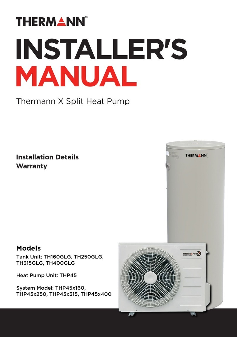
Thermann THP45x315 User manual

OWNER'S
GUIDE
Thermann X Split Heat Pump
Models
Tank Unit: TH315GLG
Heat Pump Unit: THP45
System Model: THP45x315
Operating Instructions
Warranty

33
Thermann Owner's Manual
Thermann X Split Heat Pump
Important Safety Instructions 4-5
Introduction 6
Typical Installation Layout 7
Time and Block Out Setting 8-9
System Maintenance 10
Technical Data - Heat Pump Unit 12-13
Technical Data - Tank 14
Water Supply Quality 15
Warranty Policy 16
CONTENTS

55
Thermann Owner's Manual
Thermann X Split Heat Pump
54
IMPORTANT SAFETY INSTRUCTIONS
WARRANTY
Thermann Split Heat Pump hot water units are covered by Reece for any cost of labour
and parts in the event of a component failure due to any defects that may arise either from
workmanship and/or faulty material. Product must be installed by a licensed plumber
The warranty commences on the date of installation :
RESIDENTIAL USE:
2
YEAR
Q
U
A
L
I
T
Y
G
U
A
R
A
N
T
E
E
10
YEAR
Q
U
A
L
I
T
Y
G
U
A
R
A
N
T
E
E
HEAT PUMP UNIT TANK PARTS & LABOUR
COMMERCIAL USE:
1
YEAR
Q
U
A
L
I
T
Y
G
U
A
R
A
N
T
E
E
HEAT PUMP UNIT TANK PARTS & LABOUR
1
YEAR
Q
U
A
L
I
T
Y
G
U
A
R
A
N
T
E
E
1
YEAR
Q
U
A
L
I
T
Y
G
U
A
R
A
N
T
E
E
6
YEAR
Q
U
A
L
I
T
Y
G
U
A
R
A
N
T
E
E
WARNING
This appliance is not to be used by persons (including children) with reduced physical,
sensory or mental capabilities, or lack of experience and knowledge, unless they have been
given supervision or instruction.
Children being supervised are not to play with the appliance.
Indicates content requiring “attention”.
Indicates content that is prohibited.
Indicates content with “instructions” that need to be fully followed.
Warning
Do not open the heat pump unit cover.
Caution
Do not block the air inlet and outlet.
Do not climb or put anything on top of the heat pump unit.
Do not put anything susceptible to humidity under the heat pump unit.
Do not use the heat pump unit if the installation blocks have been damaged.
Ensure no animal or plant is placed directly in front of where air is blown from the heat pump unit.
In the case of any abnormality turn the earth leakage breaker to “OFF”.
Select an installation place with consideration given to neighbours.
Remove any snow from the heat pump units after snowfalls.
Do not touch the tap while hot water is being supplied.
Check the water temperature before supplying any hot water or taking a shower.
Do not run the hot water directly into sink outlets etc.
Warning
includes the possibility of death or serious injury”.
Cautiondamage that includes the possibility of injury or damage to property.”
Do not disassemble, repair or alter the product in any way.
Do not use any damaged, altered, or bundled power code.
Do not touch the PTR valve, drainage pipe, drain outlet or drain elbow when inspecting the PTR
valve or while draining hot water.
Ensure the product is removed from any gas containers, source of fire and flammable substances.
For continued safety of this appliance it must be installed, operated and maintained in accordance
with the manufacturer’s instructions.
persons only.
This appliance may deliver water at high temperature. Refer to the Plumbing Code of
Australia(PCA), local requirements and installation instructions to determine if additional delivery
temperature control is required.
gas may accumulate in the water heater. To dissipate this gas safely, it is recommended that a hot
tap be turned on for several minutes or until discharge of gas ceases. Use a sink, basin, or bath
outlet, but not a dishwasher, clothes washer, or other appliance.
nearby. If hydrogen is discharged through the tap, it will probably make an unusual sound as with
air escaping.
Do not use the shower or any hot water for at least one minute after recovery from a power cut.
Do not install the unit anywhere it will be exposed to seawater.
Do not poke anything into the air inlet or outlet of the heat pump unit
System contains refrigerant under very high pressure. The system must be serviced by qualified
If the hot water system is not used for two weeks or more a quantity of highly flammable hydrogen
During this procedure, there must be no smoking, open flame, or any electrical appliance operating

77
Thermann Owner's Manual
Thermann X Split Heat Pump
76
TYPICAL INSTALLATION LAYOUT
GENERAL
The Thermann X Split Heat Pump must be installed in accordance with the following:
(1) Plumbing Code of Australia;
(2) Installed to meet AS/NZS3500.4 National plumbing and drainage (part 4) code hot
water supply systems – acceptable solutions.
(3) Installed to meet HB 263-2004 Heated water systems plumbing industry commission.
(4) Installed to meet AS/NZS 3000.4 Electrical installations (known as the Australian/New
Zealand wiring rules).
(5) The unit has been specifically designed for domestic hot water heating and is not suit-
able for any other purpose. If installed in a commercial application, then warranties will
be reduced to 1 year for both Tank, Heat pump unit and parts and labour.
(6) The unit is designed to operate when connected to the town water supply with a maxi-
mum operating pressure of 500 kPa. To ensure the mains pressure does not exceed this, a
pressure-limiting device that complies with AS1357 must be connected to the town water
supply line.
(7) This system delivers hot water exceeding 500C. Reference should be made to AS/
NZ3500. 4 and/or local regulations relating to the need for temperature tempering devices.
(8) The unit must be stored and transported in an upright position. Failure to do so may
render the unit faulty. Such failure is not covered under any warranty agreements.
INSTALLATION MUST BE CARRIED OUT ONLY BY AN AUTHORISED AND
APPROPRIATELY LICENSED PERSON.
The Thermann X Split Heat Pump is designed to eciently and eectively heat water in
domestic applications. This product is an external CO2 Heat Pump water heater. These units
are designed to be installed outside and as a kit (tank and heat pump unit).
Thermann X Split Heat Pump units are manufactured to have a factory output of 650C as
standard. Where connected directly to sanitary fixtures used primarily for the purposes of
personal hygiene, it must be fitted with an approved tempering valve into the hot water
piping to any bathroom and/or ensuite.
INTRODUCTION
IMPORTANT NOTE: THIS HOT WATER UNIT IS NOT FOR POOL OR SPA HEATING
Heat Pump Unit
Hot Return
Cold Supply
Tundish
Cold Water Inlet
Hot Water Outlet
To House
From Town
Water Supply
Water Tap
PTR Valve
850kPa
Stop Valve
Pressure Limiting Valve 500kPa
Thermistor Cable
To Tank Unit
Hot Water flow
Cold Water flow
To Heat Pump Unit
Tank Unit
Tundish

99
Thermann Owner's Manual
Thermann X Split Heat Pump
98
TIME AND BLOCK OUT SETTING
CURRENT TIME SETTING
This product contains a built-in clock as part of the water heating cycle logic and refers
to the current time. It is necessary to set the clock before starting to use the product. The
current time can be set in the 'Clock Setting Mode' as described below.
Note :
There is no need to adjust the time setting for the daylight saving period. Even if the
installation is conducted during the daylight saving period, the clock setting to the ordinary
time (not daylight saving time) is preferable.
1. Switching to Clock Setting Mode
Press the “Enter” key in the Clock Display Mode to switch to the Clock Setting Mode.
Time Display starts flashing once the mode is switched.
2. Setting the Clock
The time setting can be adjusted by pressing "▲” and “▼” keys. Fast forward and rewind
are available by pressing and holding down a key.
3. Confirming Time Setting
After the clock is adjusted to the current time, press the Enter key to confirm the
setting. The time display stops flashing and comes on once the setting is finished.
CAUTION :
The setting automatically goes back to the Clock Display Mode when no panel
operation is performed for more than 60 seconds in the Clock Setting Mode. If this
occurs, changes made will not be reflected to the setting. Depending on the set time,
the system will start its heating cycle.
Note :
If no buttons are pressed on the panel for more than 60, the display goes into sleep
mode and the Panel is blank except for the operation status light. Sleep Mode is
turned o when any button is pressed. ▲, ▼or Enter key is pressed.
TIME AND BLOCK OUT SETTING (CONT.)
Figure 9 : How to operate the controller
▲ ▼ Enter
“▲”key
Operation Panel
“▼”ke “Enter”key
How to use the operate controller
remove the piping cover (1 screw)
key
Figure: How to operate the controller
Figure 9 : How to operate the controller
▲ ▼ Enter
“▲”key
Operation Panel
“▼”ke “Enter”key
How to use the operate controller
remove the piping cover (1 screw)

1111
Thermann Owner's Manual
Thermann X Split Heat Pump
1110
SYSTEM MAINTENANCE
Regular servicing will help to extend the life
of the water heater, and keep it operating
safely and eciently. Your water heater
warranty is not conditional on completing
the regular servicing recommended in this
manual.
Six Month Service:
This service may be carried out by the
owner.
1. Stand clear of the Pressure &
Temperature Relief (PTR) Valve drain
pipe outlet.
2. Open the PTR Valve for approximately
10 seconds by lifting the easing lever
on the valve. Confirm water discharges
to waste through the drain pipe.
3. Lower the easing lever gently and
check it closes correctly.
Other than this, personally inspecting or
servicing any part of your water heater is
not recommended
Five Year Service (All Water Heaters):
This service should only be carried out
by a licensed tradesperson. In locations
where the water has Total Dissolved Solids
(TDS) exceeding 600 mg/L, this service is
recommended every 3 years.
The service should include the following:
• Replace the PTR Valve.
• Replace the anode
• Drain and flush the water heater
CONSIDERING A SERVICE CALL?
It is recommended that the following points
be reviewed before making a service call:
No Hot Water:
• If you have a heat pump water heater,
ensure that the power supply circuit
breaker has not “tripped”. If your water
heater is on a timed tari such as o-
peak, ensure this is operating correctly.
High Electricity Bills or Insucient Hot
Water:
• Often the hot water usage of showers,
washing machines and dishwashers
can be under estimated. Review these
appliances to determine if your daily
usage is greater than the capability of
your water heater.
• If necessary check the shower flow
rates with a bucket, measuring the
amount of water used over that period
of time. If it is not possible to adjust
water usage patterns, an inexpensive
flow control valve can easily be fitted
to the shower outlet.
• Do you have the correct size water
heater for your requirements? Sizing
details are available from your local
Reece branch.
• Is there a leaking hot water pipe or
dripping hot water tap? A small leak
can waste a large quantity of hot
water. Replace faulty tap washers and
have your plumber rectify any leaking
pipe work.
• Is the Pressure & Temperature Relief
Valve discharging too much water? See
below.
Continuous Trickle of Water from Pressure
& Temperature Relief (PTR) Valve:
This is most likely due to a build up of
foreign matter. In this case, try gently
raising the easing lever on the PTR Valve
for a few seconds, then release gently. This
may dislodge a small particle of foreign
matter and rectify the fault.
Water Discharge from PTR Valve:
It is not unusual for a small quantity of
water to discharge during the heating of
water in your storage tank. The amount of
discharge will depend on hot water usage
and size of the storage tank. As a guide, it
will discharge about 2% of the volume of
the water heated. Continuous leakage of
water from the PTR Valve may indicate a
problem with the water heater. Turn o or
shut down the water heater and contact
Customer Service.

1313
Thermann Owner's Manual
Thermann X Split Heat Pump
1312
TECHNICAL DATA - HEAT PUMP UNITTECHNICAL DATA - HEAT PUMP UNIT
Exploded Diagram of Heat Pump Unit
2
3
10
1
98
4
7
6 5
1 COMPRESSOR 6
2
FAN MOTOR
7WATER HEAT EXCHANGER CIRCULATION PUMP
3 8 MAIN PCBEXPANSION VALVE
4 9EVAPORATOR CONTROL PCB
5 FAN 10 OPERATION PCB
Heat Pump Dimensions
16
36
412.5
3026
356
659
32
327.3
58.5
122.5 122.5580
23 74
675
825 300
40.5150
With the piping
cover removed
80136
Unit : mm
(With the piping cover removed)
PERFORMANCE DATA
SPECIFICATION Unit Data
Power-supply voltage V240
Power frequency Hz 50
Installable outside air temperature 0C-10 ~ 43
Product weight kg 48
Refrigerant type -R744 (CO2)
Refrigerant weight g690
Design pressure (High/Low) MPa 14/9
Rated capacity kW 4.5
Max.capacity kW 6.0
Max.power input kW 2.5
Max.current A11
Setting outlet water 0C65
Protection rating -IPX4
Max.operating water pressure kPa 850
Noise Level dB(A) 37
Tank thermistor ON temperature 0C37
Tank thermistor OFF temperature 0C57
Installation height dierence between the tank and HP mMax 5
Piping length between the tank and HP mMax 15
Number of bends between the tank and HP -Max 6
Allowable water hardness mg/L Max 200
Allowable water pH -6.5 ~ 8.0
Circuit breaker size A20
Dry bulb 190C, Wet bulb 15.10C Inlet water 150C, Outlet water 650C

1515
Thermann Owner's Manual
Thermann X Split Heat Pump
1514
TECHNICAL DATA - TANK
Tank Specifications
WATER SUPPLY QUALITY
CHLORIDE, WATER HARDNESS AND PH
In high chloride water supply areas, the water can corrode some parts and cause them to
fail. Where the chloride level exceeds 200 mg/litre or Water Hardness level exceeds 200
mg/litre, warranty does not apply to the heat pump unit and tank unit. pH is a measure
of whether the water is alkaline or acidic. In an acidic water supply, the water can corrode
some parts and cause them to fail.
No warranty applies to the heat pump unit and tank unit where the pH is less than 6.5 or
more than 8. The water supply from a rainwater tank unit in a metropolitan area is likely to
be corrosive due to the dissolution of atmospheric contaminants.
Water with a pH less than 6.5 may be treated to raise the pH. It is recommended that an
analysis of the water from a rainwater tank be conducted before connecting this type of
water supply to the system.
350
300
250
200
150
100
50
4 5
acidic
6 7
pH
8 9
Chloride, Water Hardness
pH&Chloride and Water Hardness
No Warranty Applies
to the Heat Pump Unit or Tank Unit
No Warranty Applies
to the Heat Pump Unit or Tank Unit
Within Warranty
Specification
0
alkaline
Figure: Water Hardness
CHANGE OF WATER SUPPLY
Changing, or alternating, from one water supply to another can have a detrimental
eect on the operation and/or life expectancy of the water tank unit cylinder, PTR valve,
water heating circulation and the water heat exchanger in the system. Where there is
a changeover from one water supply to another, for example, a rainwater tank supply,
desalinated water supply, public reticulated water supply or water brought in from another
supply, then water chemistry information should be sought from the supplier or the water
should be tested to ensure it meets the warranty requirements in this installation manual.
Total volume 323L Diameter 613mm
Tank unit weight (empty) 92kg Height 1763mm
PTRV pressure rating 850kPa Hot water outlet
1535mmSensor level on tank 69% PTR valve
Heat pump return
Sensor 555mm
Cold Water inlet 201mm
Heat Pump Flow
RTN

1717
Thermann Owner's Manual
Thermann X Split Heat Pump
1716
WARRANTY POLICY
All Thermann water heaters must be installed in accordance with manufacturer’s
installation instructions and in accordance with local regulations, building codes and AS/
NZS 3000, AS/NZS 3500.4 and AS/NZS 5601.
Where a component may have failed under warranty and is replaced, the component
replaced will only be covered by the warranty for the balance of the appliance warranty
period.
Water quality must be within limits specified in table below.
pH 6.5 to 8.0
Sodium Up to 150 mg/litre or ppm
TDS (Total Dissolved Solids) Up to 600 mg/litre or ppm
Chlorides Up to 300 mg/litre or ppm
Iron Up to 1 mg/litre or ppm
Magnesium Up to 10 mg/litre or ppm
Alkalinity (as CaCO3) Up to 200 mg/litre or ppm
Dissolved (free) CO2 Up to 25 mg/litre or ppm
Total Hardness CaCO3 Up to 200 mg/litre or ppm
WARRANTY TERMS
Thermann Split Heat Pump hot water systems are covered by Reece for any cost of labour
and parts in the event of a component failure due to any defects that may arise either from
workmanship and/or faulty material.
The warranty commences on the date of installation:
Domestic
Heat Pump Unit: 6 years
Tank: 10 years
Parts & Labour: 2 years
Commercial
All components: 1 year
Parts & labour: 1 year
NEED MORE INFO?
Visit www.thermann.com.au to get the latest product information and
explore rest of the Thermann Hot Water range.

1919
Thermann Owner's Manual
Thermann X Split Heat Pump
1918
NOTES NOTES

2020
20928330 (M)
This manual suits for next models
2
Table of contents
Other Thermann Heat Pump manuals
Popular Heat Pump manuals by other brands
Sanyo
Sanyo 09KH11W operating instructions
Nibe
Nibe FIGHTER1310 HPAC Installation and maintenance instructions
Hoshizaki
Hoshizaki REMOTE CONDENSER UNIT URC-5F parts list

Viessmann
Viessmann VITOCAL 200-A Series Installation and service instructions for contractors
Rheem
Rheem MPi 551 Series Owner's guide and installation instructions

Crystal
Crystal CHP075PX user manual
