Thermedx FluidSmart User manual
1 | P a g e
Part Number - 00824 Revision K, DCO 2017-0074
© 2017 Thermedx®, LLC
Fluid Management System
FluidSmart®Operation Manual
Thermedx®, LLC - 31200 Solon Rd., Unit #1, Solon, Ohio 44139 USA
Toll-Free Phone: 1.888.542.9276
Local Phone: 440.542.0883
International Phone: 011.1.440.542.0883
www.Thermedx.com

2 | P a g e
Part Number - 00824 Revision K, DCO 2017-0074
© 2017 Thermedx®, LLC
Copyright
FluidSmart® Fluid Management System
Part Numbers: P2000, W2100
Under copyright laws, this manual may not be reproduced in any form, in whole, or in part,
without prior written permission of Thermedx®, LLC.
The Thermedx®and FluidSmart®names and logos are trademarks of Thermedx®, LLC.
The symbol ® indicates the trademark is registered in the U. S. Patent and Trademark Office and
certain other countries.
Every effort has been made to ensure that the information in this manual is accurate and details
provided are correct at the time of printing. The company reserves the right to modify the
equipment shown.
For further information, please call your local representative.
© 2017 Thermedx®, LLC.
All rights reserved.
The products described are covered by one or more Patents or Patents Pending.
Federal law (U.S.A.) restricts this device to sale by, or on the order of, a physician or properly
licensed practitioner.
Pictures are for reference only.
Specifications are subject to change without notice.

3 | P a g e
Part Number - 00824 Revision K, DCO 2017-0074
© 2017 Thermedx®, LLC
Contents
Section 1 –About this Manual.........................................................................................4
Section 2 –Description ...................................................................................................5
Section 3 –Indications for Use........................................................................................7
Section 4 –Principle of Operation...................................................................................8
Section 5 –Important Safety Information........................................................................9
Section 6 –Assembly and Setup Instructions ...............................................................13
Section 7 –Operating Instructions................................................................................18
Section 8 –Maintenance...............................................................................................31
Section 9 –Limited Product Warranty...........................................................................32
Section 10 –Troubleshooting Guide.............................................................................34
Section 11 –Specifications...........................................................................................37
Section 12 –Part Numbers...........................................................................................38
Section 13 –Symbols....................................................................................................39

4 | P a g e
Part Number - 00824 Revision K, DCO 2017-0074
© 2017 Thermedx®, LLC
Section 1 –About this Manual
The instructions within this Operation Manual contain important information for safe use of the
product. Read the entire Operation Manual, including Warnings and Cautions, before using the
product.
Failure to properly follow warnings, cautions, and instructions could result in death or serious
injury to the patient.
This Operation Manual describes the setup and use of the system including the suction canister
ring and optional secondary display.
This Operation Manual is intended for use by individuals trained in the healthcare and biomedical
professions.
WARNING
Read the entire Operation Manual before using the product. Failure to properly follow warnings,
cautions, and instructions could result in death or serious injury to the patient.
5 | P a g e
Part Number - 00824 Revision K, DCO 2017-0074
© 2017 Thermedx®, LLC
Section 2 –Description
The Thermedx®FluidSmart® is intended for irrigation, distention, fluid warming, and fluid
volume/deficit measurements in endoscopic procedures within gynecology, urology, and
orthopedic disciplines. Fluids commonly used include 0.9% saline, lactated ringer’s solution, 5%
mannitol, 1.5% glycine, and sterile water.
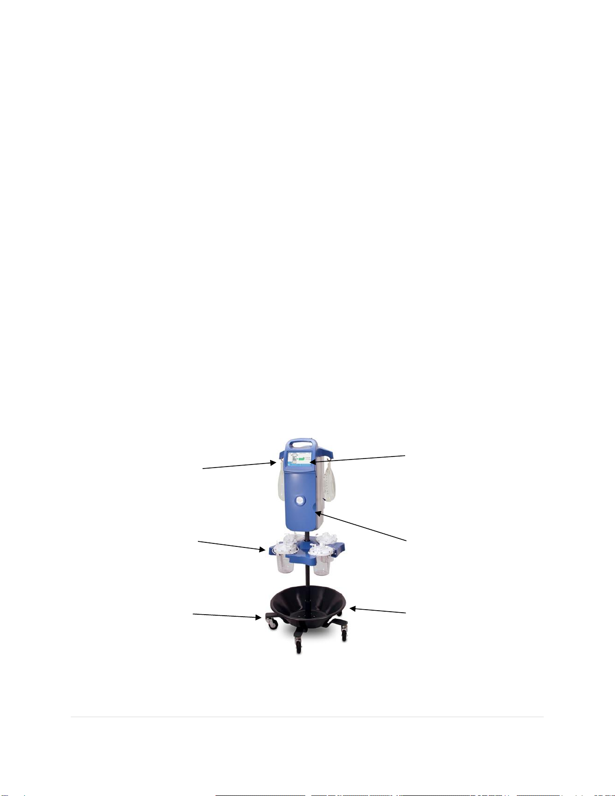
The main unit is mounted on a rolling stand which houses the technology used to warm the fluids
and the peristaltic pump used to pressurize the fluids. A touch-screen operated processor
provides closed loop controls for fluid warming and pumping. The processor monitors temperature
and pressure sensors to adjust warming power and pump speed as required. Load cells attached
to the fluid bag hooks and suction canister ring allow the processor to monitor fluid levels pumped
to and suctioned from the surgical site.
Disposable Tubing Sets
Several versions of the disposable tubing sets are available. The LL0002 is an inflow tubing set
used for endoscopic procedures with maximum fluid pressures up to 150 mmHg. The LL0004 is
an inflow and outflow tubing set used for endoscopic procedures with maximum pressures up to
150 mmHg. The LL0006 is an inflow tubing set used for endoscopic procedures with maximum
fluid pressures up to 300 mmHg. The tubing sets terminate in a luer lock fitting for use with
existing hospital equipment, typically an endoscope. Each tubing set includes spikes for the fluid
bags, tubing clamps, a cartridge for fluid warming, and a luer lock for connection to the surgical
instrument or to a tube that connects to the surgical instrument. The luer lock features a pressure
relief valve operating in a range specific to that model of tubing set.
Canister
Ring
Stand
Touch-Screen
Storage Basket
Fluid Bag
Hook(s)
Door
6 | P a g e
Part Number - 00824 Revision K, DCO 2017-0074
© 2017 Thermedx®, LLC
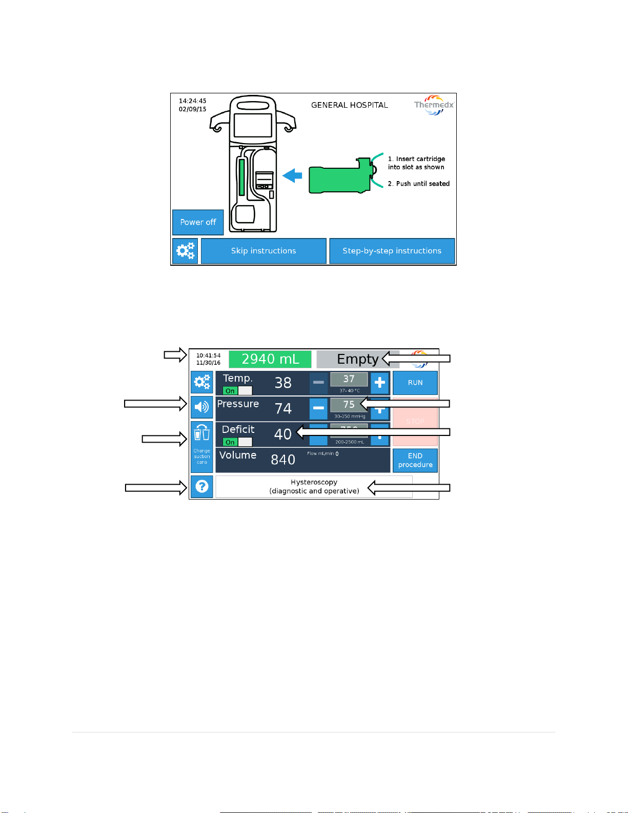
The touch-screen menu (example shown below) provides users with step by step instructions on
setup (see Section 7 for more details).
The Run screen provides real time values for Temperature (Temp.), Pressure, Deficit (if enabled),
Volume and Flow. Set-point values can be changed simply by pressing the adjustment buttons.
Note - Displayed values represent readings at the device. They may not represent in-cavity
conditions.
Date & Time
Change
Canisters
Help
Bag indicators
Set-points in grey
Real-time values
Information
Mute

7 | P a g e
Part Number - 00824 Revision K, DCO 2017-0074
© 2017 Thermedx®, LLC
Section 3 –Indications for Use
The Thermedx®FluidSmart®is intended for irrigation and fluid warming in laparoscopic
procedures and irrigation, distention, fluid warming, and fluid volume/deficit measurements in
endoscopic procedures within gynecology, urology, and orthopedic disciplines.
CONTRAINDICATIONS
General Usage:
Not for use with blood products including platelets, cryo-precipitates, or granulocyte suspensions.
Use of this device for distention is contraindicated whenever endoscopy is contraindicated. See
the Operation Manual of your endoscope for absolute and relative contraindications.
Knee, Shoulder and Small Joint Distention:
The use of this device is contraindicated for use in patients with:
Ankylosis
Inflammation or bacterial contamination

8 | P a g e
Part Number - 00824 Revision K, DCO 2017-0074
© 2017 Thermedx®, LLC
Section 4 –Principle of Operation
The FluidSmart®uses a peristaltic pump to pressurize fluids from fluid bags hanging on
either side of the unit.
Fluid is conducted through a warming mechanism that uses infrared lamps to warm the
irrigation fluids on demand to a specified set temperature, generally approximating body
temperature. The warming mechanism may be enabled during approved procedures.
Flow rates are calculated by counting pump rotations and tracking changes in the weight
of fluid bags via load cells associated with the fluid bag hooks.
IR (infrared) temperature sensors are used to measure the fluid temperature in a non-
contact method. Three sensors are used in the warming mechanism (beginning, middle,
and end of fluid path). Two additional temperature monitors are used downstream of the
warming mechanism as a safety measure independent of software.
Using the flow rate, inlet temperature, and desired set-point temperature, the IR lamp
power is calculated. The warming process is adjusted as needed based on feedback from
temperature sensors.
Temperature measurements displayed by the system are readings of fluid temperature at
the exit of the warming mechanism. These readings do not account for temperature losses
as fluid passes through the disposable tubing.
Fluid volume instilled (inflow) and fluid deficit are determined on the basis of weight using
load cells in the fluid bag hooks and suction canister ring.
Fluid pressure is monitored via pressure transducers. Redundant sensors are used for safe
operation. Pressure measurements displayed by the system are readings at the system
and may not reflect the pressure at the surgical site.
The system operates via pressure control. The system will attempt to maintain the
specified pressure (i.e. 100mmHg). Pump speed will increase or decrease accordingly.
On the basis of the selected clinical discipline and procedure the system will enable
procedure specific pressure, flow, warming, and/or deficit monitoring alarm values.
oThe default values are user adjustable within specified safety limits. Not all
features are available for all procedures.

9 | P a g e
Part Number - 00824 Revision K, DCO 2017-0074
© 2017 Thermedx®, LLC
Section 5 –Important Safety Information
The safe and effective use of surgical equipment is dependent, to a large degree, upon factors
solely under the control of the operator. There is no substitute for a properly trained and vigilant
operating room staff. It is important that the operating instructions supplied with this or any
other surgical equipment be read, understood, and followed.
WARNING
General Usage:
Read and follow all instructions, labeling, and accompanying documents supplied with this
medical device. Failure to follow instructions, including all warnings and cautions, could
lead to misuse of the device or device malfunction. Death or serious injury may occur to
the patient or user if these warnings are not followed.
Do not use the FluidSmart®in high-energy fields such as: MRI, X-RAY, portable and mobile
RF communications equipment, and other such devices. The FluidSmart®may act as a
projectile in a strong magnetic field, cause image artifacts, or not function as intended.
Do not operate the FluidSmart®in the presence of a flammable anesthetic mixture with
air, oxygen, or nitrous oxide. The risk of explosion exists if the FluidSmart®is operated in
a potentially explosive environment.
Exposed conductors on the power cord can cause an electrocution hazard. Remove device
from service if the power cord has exposed wires.
The power cord is to be used for mains disconnection.
Use only with a dedicated, properly grounded, 120 volt, 20 amp receptacle for P2000
model or 240 volt, 10 amp receptacle for W2100 model. Risk of electric shock exists if the
equipment is not connected to a properly grounded receptacle.
The tubing must be properly placed in the Bubble Detector. Failure to do so may result in
failure of the device to operate properly.
While the warming cartridge contains two bubble traps, the following are recommended
to further reduce the potential risk of an air embolism:
oRemove and purge all air from fluid lines and instrument before using. Failure to
do so can result in infusion of air into the surgical site.
oEnsure the tubing sets are fully primed with fluid prior to use, and that the
respective suction and irrigation lines are correctly attached.
oDo not reuse partially full fluid bags. Fluid bags that have been partially drained,
un-spiked, and reinstalled may contain air, which if used can increase the risk of
introducing air into the surgical site. Use only new fluid bags from which the air
has been removed.
oEnsure correct patient positioning.
oProper surveillance through the use of standard monitoring devices, such as
transesophageal echocardiography (TEE), precordial Doppler ultrasound, end-tital
CO2 monitoring, pulse oximetry, or other appropriate methods, is suggested as a
possible additional precaution, if deemed necessary by the physician for higher
risk procedures.
The FluidSmart®is for use only with Thermedx®supplied or approved parts, accessories,
and disposable sets. The device may not function as intended with the use of unapproved
parts, accessories, or disposable sets.

10 | P a g e
Part Number - 00824 Revision K, DCO 2017-0074
© 2017 Thermedx®, LLC
Do not remove cartridge from unit during operation. If removed and re-installed, unit
may fail to read actual fluid pressure accurately.
Inspect disposable packaging for damage before use. Discard disposables with damage
or punctured packaging.
The luer lock connector features an integrated pressure relief valve. Relief valve operating
pressure is specific to the model of tube set. Use the correct model tube set for the
procedure for patient safety. The correct tube set is identified on the procedure selection
screen.
Fluid deficit monitoring operates on the basis of weight. Movement, disruption, improper
setup, or user error may contribute to false readings. If the user suspects the reported
reading is not accurate a visual estimate of fluid instilled and collected should be made in
accordance with facility operating procedures.
General Distention
For liquid distention, strict fluid intake and output surveillance should be maintained. If a
low viscosity liquid distention medium is used, intrauterine instillation exceeding 2000 ml
should be followed with great care due to the possibility of fluid overload. See your
Operation Manual of your endoscope for specific indications for use.
In all situations, it is most appropriate to select the lowest fluid pressure which will provide
adequate distention and visualization.
Ensure the correct type of distention fluid is being used for the procedure and/or
accessories used, and that the fluid manufacturer’s instructions for use are followed.
Be sure to strictly monitor, evaluate, and manage fluid deficit and/or absorption levels as
appropriate for the selected procedure to prevent potential complications (e.g., fluid
overload, etc.).
oObserve the patient for electrolyte imbalances (e.g., hyponatremia, hypervolemia,
etc.) and symptoms of other fluid complications particular to the procedure being
performed (e.g., fluid intravasation, fluid extravasation, etc.).
Hysteroscopic Distention
The risk of fluid absorption is dependent on pre-requisite factors that include surgically
opening blood vessels, type of resection technique, fluid pressure level, duration of
hysteroscopy, and type of distention fluid.
In addition to monitoring fluid deficit levels and/or absorption, ensure no uterine
perforation occurs through use of the instrument or otherwise.
oIn the event a perforation occurs terminate the procedure since fluid may
otherwise be lost in the peritoneal cavity.
Intrauterine pressure should be maintained as low as possible so as to allow adequate
distention and minimize the forces potentially driving fluid, room air, and/or gas into the
patient’s circulatory system.
The risk of bleeding is dependent on pre-requisite factors that include laceration or injury
to blood vessels.
Complications of distention may include the following:
oHyponatremia: Intravasation of some distension fluids may lead to fluid overload and,
consequently hyponatremia, with its attending sequelae. This can be affected by the
distending pressure, flow rate, and duration of hysteroscopic procedure. It is critical
to closely monitor the input and outflow of the distending liquid.

11 | P a g e
Part Number - 00824 Revision K, DCO 2017-0074
© 2017 Thermedx®, LLC
oPulmonary Edema
oIdiosyncratic Reaction (Intravascular coagulopathy, allergic reaction, including
anaphylaxis)
oRupture of a fallopian tube secondary to tubal obstruction
oCerebral Edema
oHypothermia: The use of room temperature distention fluids may contribute to
intraoperative hypothermia, which may consequentially increase the risk of acidemia
and cardiac arrhythmias, decrease myocardial contractility and interfere with
coagulation.
oTubal Spasms: The use of room temperature distention fluids may contribute to the
risk of tubal spasms, which may consequentially prevent placement of the tubal plugs.
oUterine Pain: The use of room temperature distention fluid may contribute to uterine
pain in diagnostic hysteroscopy procedures.
oFor additional guidance, see the 2013 AAGL Practice Report: Practice Guidelines for
the Management of Hysteroscopic Distending Media, and AORN Recommended
Practices for Minimally Invasive Surgery.
Bladder Distention
oMonitor symptoms and signs of TUR Syndrome, including monitoring fluid deficit
levels, and identify factors that may increase its risk.
oIncrease in fluid irrigation flow rate may accelerate the normal 20 cc/min absorption
intravenously by the venous sinuses and may produce dilutional hyponatremia (TUR
syndrome of water overload).
Shoulder, Knee, and Small Joint Distention
oMonitor and assess patient for signs and symptoms of potential arthroscopic
complications associated with fluid distention media for the particular procedure which
may include fluid extravasation, neuropraxia, compartment syndrome, vascular
injuries, and tachycardia, together with airway compromise, pneumothorax, and tissue
tearing particular to shoulder arthroscopy.
oThere is a risk of extra-articular edemas in patients with pathologically changed
articular capsules and for procedures involving an opening of the capsule (e.g., lateral
release).
oSite swellings are complications which have been observed and described in the
literature in cases where roller pumps are used in arthroscopy. This build-up of fluid
can lead to post-operative swellings and pathological changes in patients. It is
therefore of the utmost importance that the surgeon monitors both the FluidSmart®
and the patient closely during the procedure.
oThe use of overly warmed fluids above 43°C may increase the risk of thermal injury,
and/or damage to articular cartilage.
oThe use of room temperature arthroscopy irrigation fluids may contribute to
intraoperative hypothermia and/or articular cartilage damage.
oThe use of room temperature irrigation fluid for arthroscopy may contribute to
intraoperative hypothermia, which may increase blood loss, and/or contribute to
articular cartilage damage.
CAUTION

12 | P a g e
Part Number - 00824 Revision K, DCO 2017-0074
© 2017 Thermedx®, LLC
Physical injury to the patient, user, and/or an adverse effect on the device or its performance
may occur if these cautions are not followed:
General
Do not use the FluidSmart®if equipment or disposable tubing set malfunction is evident.
To reduce the risk of cross contamination, do not reuse disposable tubing sets. Disposable
tubing sets are for single use only.
Do not use electrolytic irrigation fluids (0.9% sodium chloride and lactated ringer’s) with
monopolar electrocautery probes.
Federal law (U.S.A.) restricts this device to sale by or on the order of a physician.
General Distention
Pressure values shown on the touch-screen and secondary display are system pressures,
not surgical cavity pressures. For procedures where monitoring of cavity pressure is
required, it is recommended to use a secondary system of pressure monitoring.
Bladder Distention
If used for hydro-distention of the bladder be sure the patient has been properly evaluated
and correctly diagnosed with Interstitial Cystitis using the NIH Consensus Criteria.

13 | P a g e
Part Number - 00824 Revision K, DCO 2017-0074
© 2017 Thermedx®, LLC
Section 6 –Assembly and Setup Instructions
This device must be assembled and tested by authorized Thermedx®personnel, an authorized
distributor of Thermedx®, or a qualified person prior to placing the device into service. The
following steps describe how to assemble and perform preliminary setup of the product.
Read through the instructions completely prior to setting up the device.
Components Checklist:
Wheeled base with storage basket
Support pole with threaded fasteners
Main unit with power cord
Canister ring with hanger pin
Alignment tool/Allen wrench
Secondary display (Optional accessory)
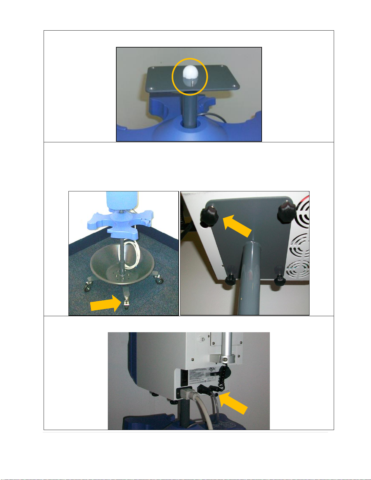
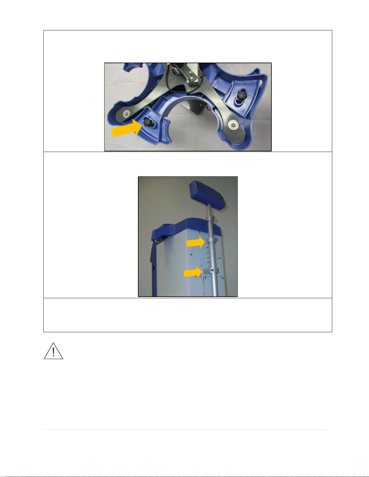
Assemble support pole and canister ring using hanger pin. Tighten (1) locking screw with
alignment tool.
Insert support pole into wheeled base. Position support pole so cord of canister ring is opposite
locking caster on wheeled base. Tighten (2) locking screws with alignment tool.
14 | P a g e
Part Number - 00824 Revision K, DCO 2017-0074
© 2017 Thermedx®, LLC
Insert alignment tool into top hole of support pole.
Install main unit onto support pole, ensuring front of main unit is in line with locking caster of
wheeled base. The main unit is seated on the support pole when the pins protruding from the
base align with the holes in the bottom of the main unit. Attach with (4) threaded fasteners
and lock washers. The preferred lifting method is one hand on the top handle, and one under
the recess on the back of the unit.
Plug in canister ring and secondary display (optional) to ports in lower rear of main unit. Install
power cord.
15 | P a g e
Part Number - 00824 Revision K, DCO 2017-0074
© 2017 Thermedx®, LLC
The canister ring has an adjustable slide feature that will accommodate canisters of 4.75 to
6.25 inches (120-160mm) in diameter. Loosen thumb screw on bottom of ring and slide to
adjust. Tighten knob again when in desired position.
Insert secondary display (optional) into rear of main unit, until end of tube is flush with lower
mount. Tighten (4) mounting screws with alignment tool.
Perform electrical safety tests as required per institutional procedure. These include but are not
limited to: leakage current, high-pot, and ground bond test.
WARNING
Grounding reliability can only be achieved when the power cord is connected to a properly
grounded receptacle. Risk of electric shock exists if the equipment is not connected to a properly
grounded receptacle and can result in death or serious injury to the patient or user.
The Electrical Safety Check must be performed by qualified personnel authorized by the institution
to perform such testing. The Electrical Safety Check must be performed and documented at least
once per year, or according to institutional policy. The degree of protection against electric shock:
Type BF Applied Part.
M

16 | P a g e
Part Number - 00824 Revision K, DCO 2017-0074
© 2017 Thermedx®, LLC
If a P2000 model, Power On the fluid
management system by plugging the unit into
a dedicated 120 volt 20 amp outlet and
turning the power switch in the rear lower
right corner to the On position.
If a W2100 model, Power On the fluid
management system by plugging the unit into
a dedicated 240 Volt 10 amp outlet and
turning the power switch in the rear lower
right corner to the On position.
The product will power on and display a
splash screen. A startup screen showing the
facility information will appear while the
software loads.
The system will prompt the user for a facility
name and address if one is not entered. Enter
information by touching an empty field and
using the on screen keyboard to fill it in.
Dismiss the keyboard with the yellow down
button, then press Save when finished. The
facility information will be included on
procedure summary tickets, as well as
displayed on the startup screen.
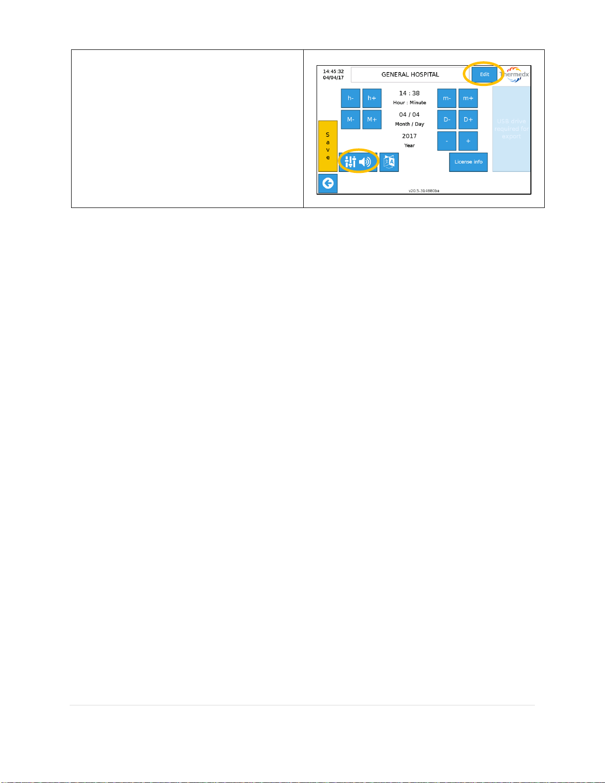
The date, time, and sound level can be
adjusted in the settings screen, accessible
with the Gear Icon.
17 | P a g e
Part Number - 00824 Revision K, DCO 2017-0074
© 2017 Thermedx®, LLC
Date and time can be adjusted using the
appropriate increment buttons. Alarm and
bag chime sound level can be adjusted by
selecting the Adjustment Icon.
Save changes to exit, or press the back
button to cancel changes. The Edit button
allows the facility information to be edited.

18 | P a g e
Part Number - 00824 Revision K, DCO 2017-0074
© 2017 Thermedx®, LLC
Section 7 –Operating Instructions
The FluidSmart®touch-screen provides step-by-step setup instructions. Arrows allow the user to
move forward and back through the steps.
Experienced users not needing step-by-step
instructions may select
Skip Instructions
.
Insert cartridge into slot as shown.
Push until seated.
Press Step-by-step instructions to
proceed.
Open pump.
Place tube in opening.
Close pump.
When complete press Right Arrow to
proceed.
Insert tubing into bubble detector.
Push until seated.
Close door.
When complete press Right Arrow to
proceed.
Prepare fluid bags (1-5 liters).
Close clamps, spike bags, hang bags. (1 per
hook).
When complete press Right Arrow to
proceed.

19 | P a g e
Part Number - 00824 Revision K, DCO 2017-0074
© 2017 Thermedx®, LLC
Place 4 canisters (if monitoring deficit) and
connect as shown. (if necessary, toggle from
multiple canister to single canister setup
using selection button at bottom of screen)
When complete press Right Arrow to
proceed to Procedure Selection.
Select:
1. Discipline
2. Tube-set/Procedure
3. Confirm selection
Once Choices are confirmed press the Right
Arrow.
Follow on-screen instructions and select
Press here to start prime.
Do not remove cartridge from unit during
operation. If removed and re-installed, unit
may fail to read actual fluid pressure
accurately.
Cartridge is filling.
1
2
3

20 | P a g e
Part Number - 00824 Revision K, DCO 2017-0074
© 2017 Thermedx®, LLC
Prime is complete.
Attach distal tubing and open clamps.
Press forward button to proceed to Run
screen.
On the Run screen:
Press RUN to start fluid flow
Use the +/-buttons to adjust set-
points.
Use toggle buttons to enable or
disable features.
Press the gear icon to access
additional settings (see below).
Pump will start, stop, reverse, and change
speed as required to maintain selected
pressure.
Press STOP to stop the pump. Pressing
STOP does not stop deficit measurement.
The flow icon indicates pump is
running.
When procedure is over press END
procedure. Doing so will freeze the deficit
measurement and display a summary of the
system performance.
This manual suits for next models
2
Table of contents
Popular Medical Equipment manuals by other brands


ICMedical
ICMedical CRYSTAL VISION 450D OPERATING AND INSTALLATION Manual

I-care
I-care Icare HOME TA022 Patient guide

B. Braun
B. Braun Aesculap Instructions for use/Technical description

Hillrom
Hillrom O-NTS Instructions for use

3D Histech
3D Histech Pannoramic MIDI 1.15 user guide

B. Braun
B. Braun HORIZON Nxt Operation manual


