Unika PRO MMD User manual

PRO MMD
USER MANUAL
6F, No.168, Xin-Hu 2nd Rd.
Nei-Hu District, Taipei City. 11494.
Taiwan, R.O.C.
+886 2 27933017
+886 2 27928264
UNiKA Electronic Co., Ltd.
www.unikapro.com
PRO SERIES AUDIO INTERFACE
DESIGN & MADE IN TAIWAN
MULTI-MEDIA DIRECT BOX
Index
GENERAL PRECAUTION BEFORE USE
PRODUCT OVERVIEW
CAUTION
PARAMETER TEST CONDITIONS
FEATURES
APPLICATIONS
APPEARANCE PARTS & FUNCTIONS
ISO TRANSFORMER SCHEMATIC
INPUT PAD ATTENUATION
ELIMINATING GROUND LOOP NOISE
CONNECTION GUIDE
SPECIFICATIONS

UNiKA PRO MMD User Manual
1
GENERAL PRECAUTION BEFORE USE
Thank you for purchasing the UNiKA PRO SERIES AUDIO INTERFACE. Before using,
please read this manual carefully and pay attention to every detail that you must pay
attention to. If you use a mixer to connect to this interface, please turn off the mixer
power and +48V phantom power before connecting, and then turn on the power and
phantom power in turn after inserting the signal cables. For passive models, please do
not turn on the phantom power to avoid leakage or damage the equipment.
If using a model with a volume knob, turn the volume knob to the minimum. During
use, please do not plug or unplug the wires arbitrarily to avoid signal loss. Please
refer to the following instructions for the soldering method of the plugs to ensure the
expected level and keep the signal smooth.
If you need further installation or operation guidance, please directly contact UNiKA's
dealer or distributor, or write to the following mail address for help:
PRODUCT OVERVIEW
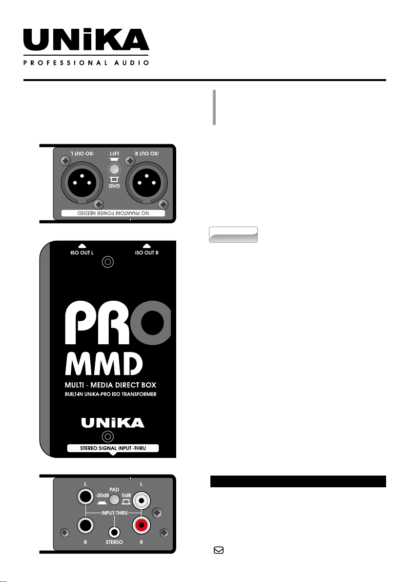
PRO MMD is a dedicated DI box for passive multimedia, without the need to install
battery or provide phantom power.
PRO MMD has a pair of built-in UNiKA-PROTM EI30A10E 1+1:1+1 isolation
transformers which has a special copper foil layer and a dedicated ground layer, which
allows this device to restore high signal/noise ratio and dynamic sound, and can avoid
unnecessary leakage caused by radio frequency interference, ground interference and
potential difference.
PRO MMD is particularly suitable for play deck, computer, and video equipment.
It converts high-impedance signals into low-impedance balance signals which is
convenient for extending the wiring distance and blocking interference.
The input end of PRO MMD adopts two TRS sockets, a pair of RAC sockets and a
mini TRS socket, any one socket can be used as input or through out. In addition, it
is equipped with a 0/-20dB attenuation switch, which is suitable for various types of
audio signals with high and low impedance. The output terminal is also equipped with
a ground/oating button, in order to quickly eliminate ground noise.

2
UNiKA PRO MMD User Manual
FEATURES
• Built-in UNiKA-PROTM EI30A10E isolation transformer for each channel
• The input socket uses a pair of TRS jacks, a pair of RAC and a mini TRS.
• All input jacks can be using for through out.
• There is 0dB/-20dB input signal attenuation switch
• The output is equipped with a GND/LIFT switch
PARAMETER TEST CONDITIONS
In the development and manufacturing process, Audio Precision's 2700 series and 500
series are used to test and verify electrical characteristics.
This product has undergone rigorous inspection before leaving the factory. If
customers encounter failures during use, please contact your local dealer or distributor
for replacement or repairing, do not disassemble the case or replace parts by yourself,
which will invalidate the warranty.
For details, please refer to the warranty regulations in the enclosed warranty card, and
ll in the details, and get a valid stamp or signature of the dealer or distributor.
CAUTION
APPLICATIONS
• Convert unbalanced signals of various audio equipment into balanced signals,
such as the headphone or line output of computers, play deck or mobile devices.
• Convert the unbalanced signal of the electronic musical instrument into a balanced
signal and send it to the mixer.
• Isolate the leakage and hum be generated by potential when two different systems
are connected but powered by separate power system or power generator.

UNiKA PRO MMD User Manual
3
①Left channel signal output : XLR terminal,
isolated transformer's balanced output, no
need to use +48V phantom power.
②Output grounding/floating switch: when
the switch is not pressed,the first pin
(PIN-1) of XLR is grounded. PIN-1 will be
disconnected from ground after pressing.
This button should depend on the system.
Used in the situation, in order to isolate the
ground loop noise or leakage.
③Right channel signal output: XLR terminal
isolated transformer's balanced output, no
need to use +48V Phantom power.
④ L/R TRS input and through out: balanced
or unbalanced input, used to connect
electronic musical instruments or audio
playback equipment, and can be used as a
through output of Mini TRS and RCA.
⑤PAD input attenuator switch: provide
two 0/-20dB Option, when inputting
signals of various impedances and levels.
It can be attenuated by 20dB to avoid
overload or clipping.
⑥Mini TRS input and through out: Mini
TRS input to connect to mobile devices or
computers, and can be used as a through
output of Mini TRS and RCA.
⑦Stereo RCA input and through out: Used
to connect to consumer playback equipment
or professional video card, and can be used
as a through output of L/R TRS and Mini
TRS.
① ②
APPEARANCE PARTS & FUNCTIONS
④ ⑥ ⑦
③
⑤

4
UNiKA PRO MMD User Manual
ISO TRANSFORMER SCHEMATIC
1 5
10 6
Screen Secondary
Cooper foil/
Core
Primary
UNiKA-PROTM EI30A10E
1
2
4
5
6
7
8
9
3
10

UNiKA PRO MMD User Manual
5
The built-in channel independent balanced isolation
transformer has solved the potential difference
leakage problem. When the system causes a ground
loop due to poor wiring, the noise can be eliminated
through the GND/LIFT button.
The GND/LIFT button determines whether pin-1 of the
output XLR is grounded, grounded when it bounces,
and disconnected from ground when pressed.
ELIMINATING GROUND LOOP NOISE
INPUT PAD ATTENUATION
The most widely used DI box is to connect
electronic musical instruments, sound source
broadcasting Amplifiers and computers, convert
their output signals into balanced signals, and then
extend the transmission distance.
The most ideal state is to set the attenuator to 0dB
position (button up). For some high-level output
signals, you can press the button to make the signal
is attenuated by 20dB to avoid clipping caused by
signal overload.
When the button is pressed, the PAD indicator on
the right will light up.

6
UNiKA PRO MMD User Manual
CONNECTION GUIDE
Connect the balanced wire
from ISO OUT to the mixer
The unbalanced connection, pin-2 is hot, pin-3 is shield paralleled with pin-1.
TS Unbalance plugTRS Balance plug
Output from computer,
player or electric
instrument through
TS/TRS/Mini TRS/RCA
1-Shield pin
2-Hot pin
3-Cold pin
12
3
1
3
2
XLR-Female
connector
XLR-Male
output jack
Tip-Signal Hot
Ring-Signal Cold
Sleeve-Shield
Tip-Signal
Sleeve-Shield

UNiKA PRO MMD User Manual
7
SPECIFICATIONS
PRO MMD
Circuit principle Passive/Transformer balance output
Input connector 2 x TRS, 1 x Mini TRS, 1 pair of RCA
Thru connector Any one of the input sockets
Input pad switch 0/-20dB push button
Output connector 2 x Male XLR through ISO Transformer
Output GND/LIFT switch Shared push button
Input impedance 1KΩ / 0dB & -20dB
Output impedance 50Ω
Max. input level before clipping +22dB
Max Output level +22dB
Frequency response 20Hz-20KHz, -0.3/0.9dB
S/N ratio @20Hz~20KHz un-weight >120dB
T.H.D. @1KHz 0dBV output <0.02%
Transformer Ratio 1:1+1:1
Chassis 1.6mm/1.2mm steel cabinet and chassis
Surface nished Durable complex painting
Dimension (W x D x H) 78 x 124 x 46 mm
Weight 0.55kg
Shipping weight 0.65kg
Packing per carton 20pc/14kg
Shipping dimension per carton 350 X 310 X 207 mm
(Specications are subject to change without notice.)

1. Equipment
EU DECLARATION OF
CONFORMITY
Product name Passive multi-media direct box
Model PRO-MMD
EAN Code 4711064410242
2. Manufacturer
Manufacturer UNiKA Electronic Co.,Ltd.
Address 6F, No.168, Xinhu 2nd Roadn, Nei-Hu, Taipei, Taiwan
EMI:
EN 55032:2015 IEC 61000-4-3:2006+A1:2007+A2:2010
EN 61000-3-3:2014 IEC 61000-4-42012
EN 61000-3-3:2013 IEC 61000-4-5:2014+A1:2017
EMS: IEC 61000-4-6:2013/CORE1:2015
EN 55035:2017 IEC 61000-4-8:2009
IEC 61000-4-2:2008 IEC 61000-4-11:2-4+A1:2017
7. Where applicable, the above equipment will be tested and revision of existent certicate by WH
Technology Corp. (TAF Accreditatio Number:2954) for compliance With EMC requirements
set forth in the EUROPEAN COUNCIL DIRECTIVE 2014/30/EU and the technical standards
mentioned above. The results of testing in this report apply only to the product/system, which
was tested. Other similar equipment will not necessarily produce the same results due to
production tolerance.
8. The technical le is available from the manufacturer at the address above
Signed for and on behalf of: UNiKA Electronic Co.,Ltd.
Place of issue: Taipei
Date of issue: May 03th, 2021
Name: Yung-Ho Hsu
Position: Marketing & Product director Signature:
3. This declaration of conformity is issued under the sole responsibility of the manufacturer.
4. Object of the declaration, Product: Direct box for musical instrument and A/V device.
5. The object of the declaration described in point 4 is in conformity with the relevant
Union harmonisation legislation 2014/30/EU The Electromagnetic Compatibility Directive
6. References to the relevant harmonised standards used, or references to the specications in
relation to which conformity is declared:
This manual suits for next models
4
Table of contents
Other Unika Recording Equipment manuals

Unika
Unika PRO IS2 User manual

Unika
Unika PRO Series User manual

Unika
Unika PRO Series User manual

Unika
Unika PRO Series User manual

Unika
Unika PRO Series User manual

Unika
Unika GEQ-215 User manual

Unika
Unika RACK POWER User manual

Unika
Unika EQ-815 User manual

Unika
Unika POWER 4800 User manual

Unika
Unika Stage Series User manual