KTS-Electronic GPA 500 User manual

Ground
Penetrating
Analyzer
GPA 500
User’s Manual
KTS 3D
KTS-Electronic GmbH & Co. KG
Germany

KTS-Electronic GmbH & Co. KG –GPA 500
Table of content
1General guidelines.........................................................................................................4
1.1 Preface................................................................................................................4
1.2 Important details ................................................................................................4
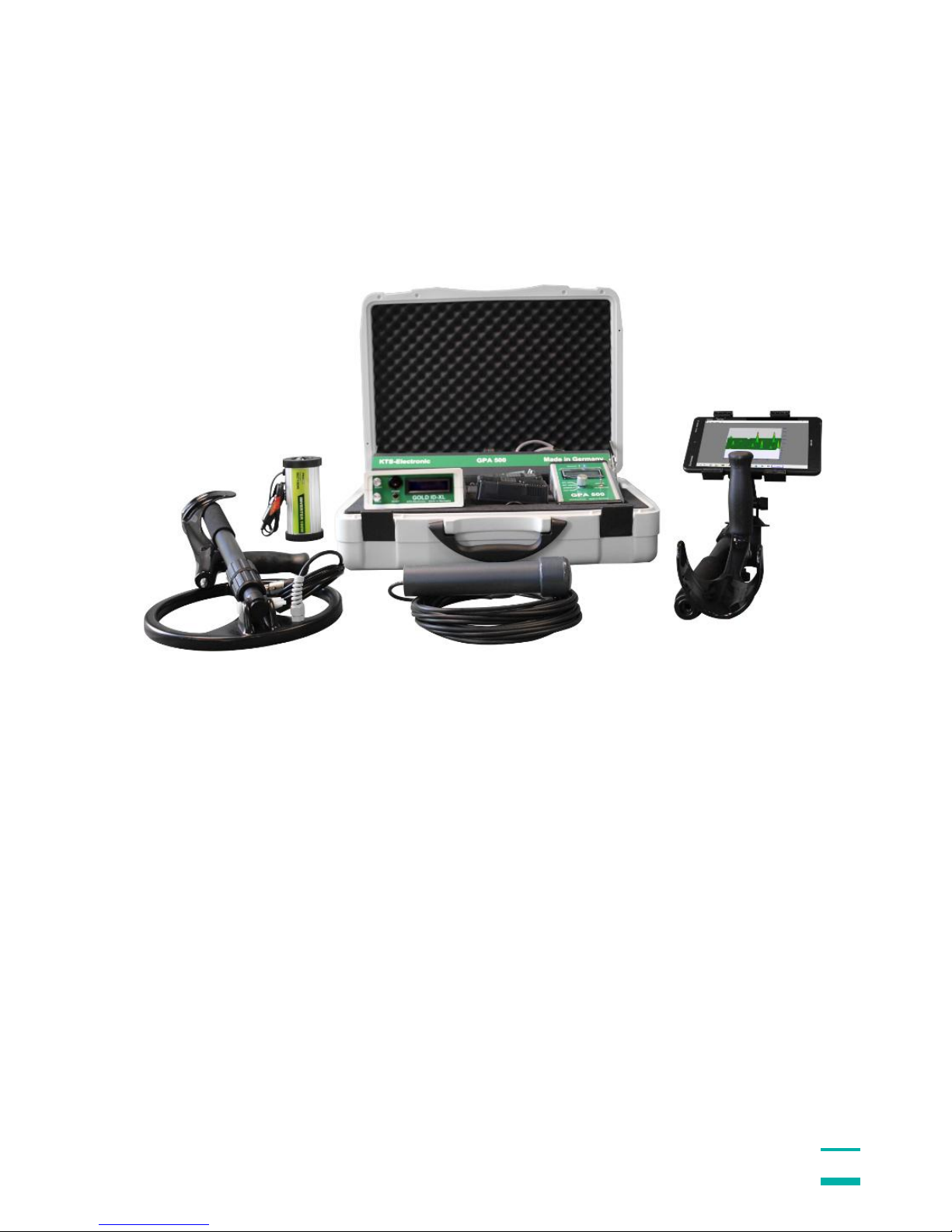
1.3 Scope of delivery ...............................................................................................4
2Hardware operation for GPA 500..................................................................................6
2.1 Assembly of the universal probe ......................................................................6
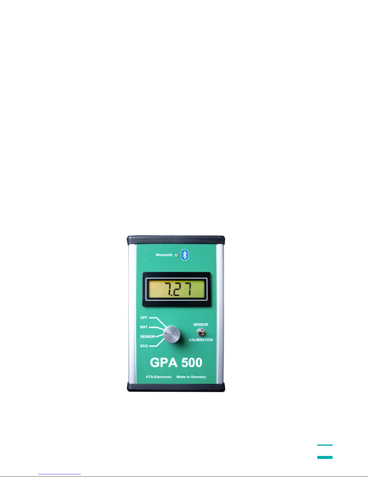
2.2 Electronic Unit....................................................................................................7
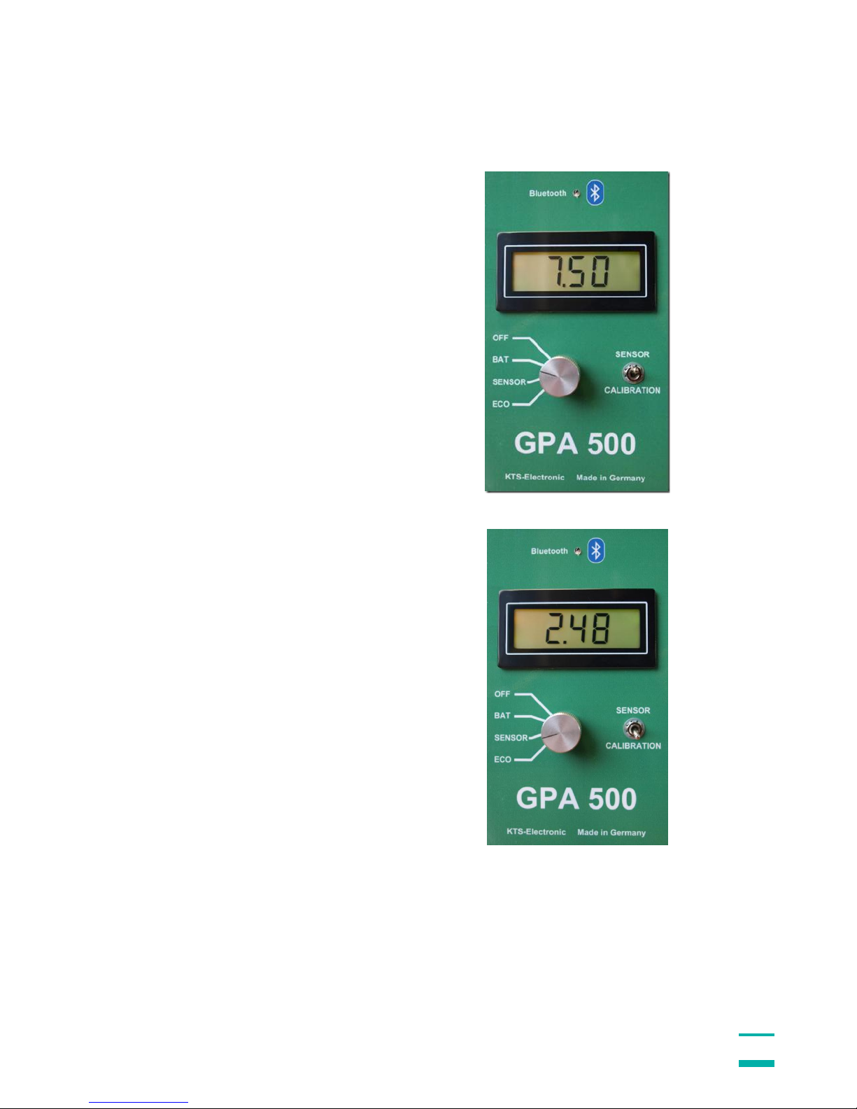
2.3 Starting the electronic .......................................................................................8
3Start of program...........................................................................................................10
3.1 Preadjustment KTS 3 D....................................................................................10
3.1.1 Start-button........................................................................................................11
3.1.2 Completion of measurement ..............................................................................11
3.1.3 Transfer of measurement data...........................................................................11
3.1.4 3D presentation..................................................................................................11
3.2 Search process (measurements)....................................................................12
3.2.1 Search in one direction.......................................................................................12
3.2.2 Search in counter direction.................................................................................13
4Program operations.....................................................................................................13
4.1 Main window.....................................................................................................13
4.1.1 Toolbar...............................................................................................................14
4.1.2 Display range.....................................................................................................14
4.2 Menu bar...........................................................................................................14
4.2.1 Data menu .........................................................................................................14
4.2.2 Display menu .....................................................................................................14
4.2.3 Options menu.....................................................................................................14
4.2.4 Info menu...........................................................................................................14
4.3 Options window ...............................................................................................15
4.3.1 Paths..................................................................................................................15
4.3.2 Colors and coordinates ......................................................................................15
4.3.3 Languages.........................................................................................................16
4.3.4 Serial Interface...................................................................................................16
5Data recordings............................................................................................................17
5.1 Modulation before data recording...................................................................17
5.1.1 Display during data recording.............................................................................17
5.1.2 Display after completion of data recording..........................................................18
5.2 Display alternatives..........................................................................................18
5.2.1 Proportional or square display............................................................................18
5.2.2 Data presentation - absolute or relative..............................................................18
6Search process............................................................................................................19
6.1 Search with the universal probe .....................................................................19
6.2 Live mode.........................................................................................................20
6.3 3D-search mode...............................................................................................20
6.4 Rechargeable battery and charger..................................................................21

KTS-Electronic GmbH & Co. KG –GPA 500
Chapter GOLD ID-XL
7Electronic Unit .............................................................................................................22
7.1 Back side..........................................................................................................23
8Search process............................................................................................................23
8.1 Search recommendations and hints for Reset operation..............................24
8.2 Exact location of metal objects.......................................................................26
9Search progress...........................................................................................................27
9.1 Assembly..........................................................................................................27
9.2 Usage and selection of searchcoils................................................................27
9.3 25 cm coil..........................................................................................................27
9.4 Cylindrical coil..................................................................................................28
9.5 Battery and chargers .......................................................................................28
10 Error signals.....................................................................................................29
11 Technical data..................................................................................................29
12 Driver-reinstalling (only by reinstalling).........................................................30
12.1 Bluetooth pairing .............................................................................................30
13 System requirements and license agreement................................................32
13.1 System requirements.......................................................................................32
13.2 License agreement...........................................................................................32
13.3 Utilization regulations......................................................................................32
13.4 Liability exclusions..........................................................................................32
14 Warranty ...........................................................................................................33
14.1 After expiration date ........................................................................................33
14.2 Care...................................................................................................................33
14.3 Legal note.........................................................................................................34
15 Contact..............................................................................................................34

KTS-Electronic GmbH & Co. KG –GPA 500
4
1 General guidelines
1.1 Preface
Congratulations on your purchase of the high performance detector GPA 500.
Since programs are already pre-installed, the assembly is quite simple. The
instruction manual is written in plain style and furnished with numerous illustrations,
so that the practicable application will be problem-free.
This instruction has been developed by KTS-Electronic GmbH & Co. KG. Any
alterations or duplications are only allowed with written permission of KTS-Electronic.
KTS-Electronic reserves the right to modify the instruction with new knowledge at
anytime. The new instructions always can be downloaded gratuitously from our
website.
Your KTS-Electronic Team
1.2 Important details
Please note:
Keep dry.
Avoid conducting overhead lines
Do not use cell phones during operation
Do not process measurements during thunderstorms
Accurate operation is only guaranteed with a fully charged battery
For operation or loading use solely the components enclosed or released by KTS.
1.3 Scope of delivery
Hardware:
GPA 500 electronic unit with Bluetooth® incl. installed Li-ion battery
GPA Universal probe 48 cm (18“) incl. 2-part carbon telescope bar
Tablet Computer with pre-installed KTS software incl.Li-ion battery and charger
Quick-charger 220 Volt including 110 Volt adapter
Transformer to charge in car
Headphones
Solid hard-top case
Software:
Newly developed KTS-3D software (pre-installed on PC)
USB stick with software for processing data on other computers

KTS-Electronic GmbH & Co. KG –GPA 500
5
Additionally: GOLD ID-XL metal discrimination
GOLD ID-XL electronic unit incl. installed li-ion battery and leather bag
25 cm (10") Ø searchcoil (waterproof) with carbon telescope bar
Cylindrical coil 5 cm Ø (waterproof) with 10 m cable
Powerful quick-charger 220 Volt, inverter with car loading cable and 110 Volt
adapter
Service:
English, German, French or Spanish user's manual
2 years manufacturer's warranty for the entire scope of delivery (incl. hardware
and software)

KTS-Electronic GmbH & Co. KG –GPA 500
6
2 Hardware operation for GPA 500
2.1 Assembly of the universal probe
Plug the bar into probe’s mount. Then insert the remaining parts in correct order. The
universal probe can now be attached to the holder. After that the sensor cable must
be connected. Your device is now ready for operation.
Fig.: Telescope bar
Please do not overwind the thread
Fig.: 4-part demountable universal probe
Fig.: Telescope bar with universal probe and tablet

KTS-Electronic GmbH & Co. KG –GPA 500
7
2.2 Electronic Unit
Turn-switch: The rotary control has 4 shift positions:
OFF Device is turned off.
BAT Current battery voltage (should be between 7 and max. 8.2 Volt)
SENSOR Display shows sensor values.
ECO Power save mode, display lighting is not active.
Toggle-switch: SENSOR/CALIBRATION
SENSOR Shows battery voltage (BAT) or current value sensor (SENSOR or ECO).
CALIBRATION Shows calibration value.
The calibration is conducted by a microprocessor and is carried out automatically on
every soil without the necessity of further modulations. The GPA set therefore is
applicable on every soil type.
The measured data is automatically digitized and will be wirelessly transformed to the
tablet computer via Bluetooth. A blue LED flashes after switching on, constant light
signifies the Bluetooth connection.
Fig.: Electronic unit

KTS-Electronic GmbH & Co. KG –GPA 500
8
2.3 Starting the electronic
To control the current battery condition
turn the knob to BAT and after that the
toggle switch to SENSOR. The value
must always stand over 7.5 Volt (if not
the case, please charge battery).
Then turn the rotary switch to SENSOR
or ECO to read the sensor or calibration
data. The sensor data should always be
between 1-4 ....

KTS-Electronic GmbH & Co. KG –GPA 500
9
... and CALIBRATION approx. 2.5
(before the calibration automatically is
set it could temporarily show other
values).

KTS-Electronic GmbH & Co. KG –GPA 500
10
3 Start of program
The Bluetooth-connection allows a fast and save transfer of measured data from
GPA 500 to the tablet computer –in contrast to other devices, which record data via
parallel interface.
Boot up the PC and double-click on the KTS-3D icon, then start KTS software. GPA
500 automatically will be connected to the computer (be sure that GPA 500 is
activated before you start KTS 3D-Software). Should the connection not take place,
please see 6.6.
3.1 Preadjustment KTS 3 D
With the "new" button on the display the setting window is opened and
the computer requires the input of track number, track length, values per track and
measurement speed, etc.

KTS-Electronic GmbH & Co. KG –GPA 500
11
3.1.1 Start-button
By pressing the start button the search begins. On screen the results are displayed 2-
dimensional. After all values are measured, the program stops automatically and is
ready for the next track.
3.1.2 Completion of measurement
After completion of the last track you are going to be asked, if you want to save the
measurements. With the O.K.-button the measurement is stored automatically in a
user-defined file.
3.1.3 Transfer of measurement data
The provided USB-stick can also be used for the transfer of measurement data; you
are able to transmit to other PCs and call up all informations for further processings.
3.1.4 3D presentation
3D presentation shows every modification and its dimension.

KTS-Electronic GmbH & Co. KG –GPA 500
12
3.2 Search process (measurements)
The GPA is a measuring device, which can measure alterations of ground anomalies
caused by metal objects, soil structure or excavations and can discriminate from
normal ground magnetism. Correct results strongly depend on ground type and
measuring method. Areas to be measured should not have electric fields (like high
voltage cables or earth wires) or strong mineralising or wet grounds, because they
influence the measurement. The dryer the soil, the more precise the results.
Split the area you want to measure into even tracks. You may choose between 2
methods:
3.2.1 Search in one direction
If you have chosen the search in rectification, you should return to the starting point
after completion of each track and press the start button (for measurements of the
second track).

KTS-Electronic GmbH & Co. KG –GPA 500
13
3.2.2 Search in counter direction
If you have decided to search in counter direction, you should turn around after
completion of each track, step approx. 50 cm (20 inches) to the right or to the left and
continue with the next track by pressing the start button.
For precise measurements the walking speed should be constant while covering a
distance. Hereby objects can be detected at the same spot during counter direction.
For exact measurements track lengths between 5 to 10 meters (16 to 32 ft.) are
expedient.
4 Program operations
The program serves as indication of magnet field data in colored, three dimensional
representation.
4.1 Main window
After start of program the empty main window appears with menu and tool bar,
setting and display range.
Initially display range is
empty.

KTS-Electronic GmbH & Co. KG –GPA 500
14
4.1.1 Toolbar
Some buttons are combined for fast operation. These are from left to right:
New start of set-up for data acquisition
Start starts a data acquisition
Stop stops the current data acquisition
Open reads a stored file
Live starts the live mode
Save saves the current file
Peak switches between absolute and relative representation
Norm resets main-representation to basic setting
Prop switches between proportional and quadratic representation
Zoom in and out with buttons [+] and [-]
4.1.2 Display range
Display shows a 3-dimensional, colored presentation of the measured values. While
moving the mouse with pressed left mouse button the presentation can be rotated.
4.2 Menu bar
4.2.1 Data menu
The data menu indicates entries to open and store measurement data. The stored
measurement data is marked through the suffix GRD.
New starts a data recording with connected external measurement hardware.
A pop-up window appears for the setting of measurement conditions.
Copy into clipboard copies the current view into the temporary storage, so
that it can be inserted into every image editing application.
End ends program.
4.2.2 Display menu
In this menu you can switch between graphical and numerical view of measurements.
4.2.3 Options menu
With the options menu item a new window for the setting of program options is
indicated. A description of various possibilities is shown there.
4.2.4 Info menu
Delivers informations about the present version.

KTS-Electronic GmbH & Co. KG –GPA 500
15
4.3 Options window
The options window is divided into four categories:
4.3.1 Paths
With the path modulation the index is defined for data storage. A selection dialogue
appears after the [search] button is pressed.
4.3.2 Colors and coordinates
Here colors for the coordinate display, graphic cursor and background can be
selected. After the appropriate corresponding buttons have been activated, a color-
selection dialogue shows up.

KTS-Electronic GmbH & Co. KG –GPA 500
16
4.3.3 Languages
For operation the program can completely be switched to languages shown below.
4.3.4 Serial Interface
In case of reinstallation you can select the utilized Comport (see page 30, 12.1
Bluetooth pairing).

KTS-Electronic GmbH & Co. KG –GPA 500
17
5 Data recordings
5.1 Modulation before data recording
Before data acquisition various settings must be carried out. The track length defines
–together with the values per track –the distance (see field step width) between
every single measurement. The values per track are limited to 100 maximum.
After pressing the [Start] button the measurement is activated; this can be carried out
either manual or time-controlled (standard setting is 0.2 sec). With the [Cancel]
button a program termination is given at all times. The switch between consensual
and contrasensual movement is also possible.
5.1.1 Display during data recording
During data recording the display turns up two-dimensional and in colored grading.
Of course, the shown colors are dependend on the selected modulation. The end of
a track is displayed, after confirmation the new track will be measured. A storage
request appears at the end of the last track; afterwards a switch to the three-
dimensional representation takes place.

KTS-Electronic GmbH & Co. KG –GPA 500
18
5.1.2 Display after completion of data recording
Representation results from the two-dimensional image shown in 5.1.1
5.2 Display alternatives
5.2.1 Proportional or square display
With the button [prop.] the representation switches between proportional and
quadratic view. In the quadratic representation the display occurs with square
elements. Details partially are better recognized here. The relation between track
length to field width is not taken into account. The proportional representation is
displayed under consideration of the real track length and field width like it was setted
in [data recording].
Note:The actual measured length / width is only given through the setting [data
recording]. The correct input of the exact length and width is essential.
5.2.2 Data presentation - absolute or relative
There is the possibility to switch between absolute or relative data presentation. With
the absolute presentation the Z-axis is expanded to the full available measuring
range. With the relative presentation the value range is based on the smallest resp.
the largest measured value. This way a maximum detailed resolution is obtained
which also has effect on the color representation.

KTS-Electronic GmbH & Co. KG –GPA 500
19
6 Search process
During soil analysis several search modes are selectable.
6.1 Search with the universal probe
Activation over the rotary switch.
Battery condition is readable when rotary switch stands on Bat.
Wireless connection via Bluetooth to the electronic unit.
Turn the probe so that the arrow (see alongside the probe) points to the ground during
the search (this way you will attain the highest search performance).
Control of calibration (approx. 2.5) and
monitoring of sensor value.
Make sure that the indicated value is between 0 to 5. Should this not be the case,
change the search direction slightly so that above value shows up.
The further search process is described under 6.3.

KTS-Electronic GmbH & Co. KG –GPA 500
20
6.2 Live mode
To mark relevant sectors, it is reasonable to scan large areas in the live mode at first
so that afterwards controlling in 3D is more precise. If the live mode stops
unexpectedly, press the “start” button again and continue with the search.
6.3 3D-search mode
For precise ground examinations the area must be divided into tracks. The tracks can
be scanned in same direction or in alternate direction. The moving direction is
selectable in the settings window.
The track length can be determined variably (during the search after large objects or
excavations longer track lengths can be selected;.for the search after small items
shorter track lengths are recommendable).
Table of contents
Other KTS-Electronic Metal Detector manuals