Thermo 3307 Operating instructions

Models:
3307/3308 and 3310/3311
Steri-Cult CO2Incubator
Controlled RH with Sterilization Cycle
Operating and Maintenance Manual
Manual No: 7013307 Rev. 3

Steri-Cult Incubator _______________________________________________________________________________
i
Model Size Voltage
3307 Medium 115
3308 Large 230
3310 Medium 115
3311 Large 230
If the incubator is not used in the manner speci-
fied in this operating manual, the protection pro-
vided by the equipment design may be impaired.
Read This Instruction Manual.
Failure to read, understand and follow the instructions in
this manual may result in damage to the unit, injury to operat-
ing personnel, and poor equipment performance.
CAUTION! All internal adjustments and maintenance must
be performed by qualified service personnel.
The material in this manual is for information purposes only. The
contents and the product it describes are subject to change with-
out notice. Thermo Electron Corporation makes no representa-
tions or warranties with respect to this manual. In no event shall
Thermo be held liable for any damages, direct or incidental, aris-
ing out of or related to the use of this manual.
MANUAL NUMBER 7013307
-- -- 4/11/05 Added heat/CO2information pertaining to door openings in Section 5.7 ccs
3 22767/IN-3242 3/9/05 Corrected RH sensor from 290154 to 290174, electrical schematics ccs
2 -- 10/21/04 Updated sterilization Checkpoints concerning stacked units (per D. Figel) ccs
-- 22434/IN-3211 8/25/04 Updated water quality description for water bottle ccs
1 21730/SI-9181 6/15/04 Schematic updates, alternate source for 250085 solenoid valve ccs
0 22150/IN-3177 2/17/04 Standard manual size ccs
-- 21951/IN-3150 12/19/03 Inner door switch only to P/N 360263 ccs
-- 21980/IN-3156 11/07/03 Added min/max load and analog output boards max external cable length ccs
- 21596/IN-3124 10/24/03 New temperature sensor thermistor 290185 (glass enclosed) ccs
REV ECR/ECN DATE DESCRIPTION By

Steri-Cult Incubator _________________________________________________________________________Warnings
ii
Important operating and/or maintenance instructions. Read the accompanying text carefully.
Potential electrical hazards. Only qualified persons should perform procedures associated with this symbol.
Hot surface(s) present which may cause burns to unprotected skin or to materials which may be damaged by elevated
temperatures
√ Always use the proper protective equipment (clothing, gloves, goggles, etc.)
√ Always dissipate extreme cold or heat and wear protective clothing.
√ Always follow good hygiene practices.
√ Each individual is responsible for his or her own safety.

Steri-Cult Incubator ___________________________________________________________________________Service
iii

Model 3307/3308 _______________________________________________________________________________
iv
Warranty Notes
Information You Should Know Before Requesting Warranty Service
•Locate the model and serial numbers. A serial tag is located on the unit itself and on
the operating manual shipped with the unit.
• For equipment service or maintenance, or with technical or special application inquiries,
contact Technical Services at 1-888-213-1790 or 1-740-373-4763 (USA and Canada).
Outside the USA, contact your local distributor.
Repairs NOT Covered Under Warranty
• Calibration of control parameters. Nominal calibrations are performed at the factory;
typically ±1°C for temperature, ±1% for gases, and ±5% for humidity. Our service person-
nel can provide precise calibrations as a billable service at your location. Calibration after
a warranty repair is covered under the warranty.
• Damage resulting from use of improper quality water, chemicals or cleaning agents
detrimental to equipment materials.
• Service calls for improper installation or operating instructions. Corrections to any of
the following are billable services:
1) electrical service connection
2) tubing connections
3) gas regulators
4) gas tanks
5) unit leveling
6) room ventilation
7) adverse ambient temperature fluctuations
8) any repair external to the unit
• Damage resulting from accident, alteration, misuse, abuse, fire, flood, acts of God,
or improper installation.
• Repairs to parts or systems resulting from unauthorized unit modifications.
• Any labor costs other than that specified during the parts and labor warranty
period, which may include additional warranty on CO2sensors, blower motors,
water jackets, etc.

Steri-Cult Incubator __________________________________________________________________Table of Contents
Table of Contents
Section 1 - Installation and Start-up . . . . . . . . . . . . . . .1 - 1
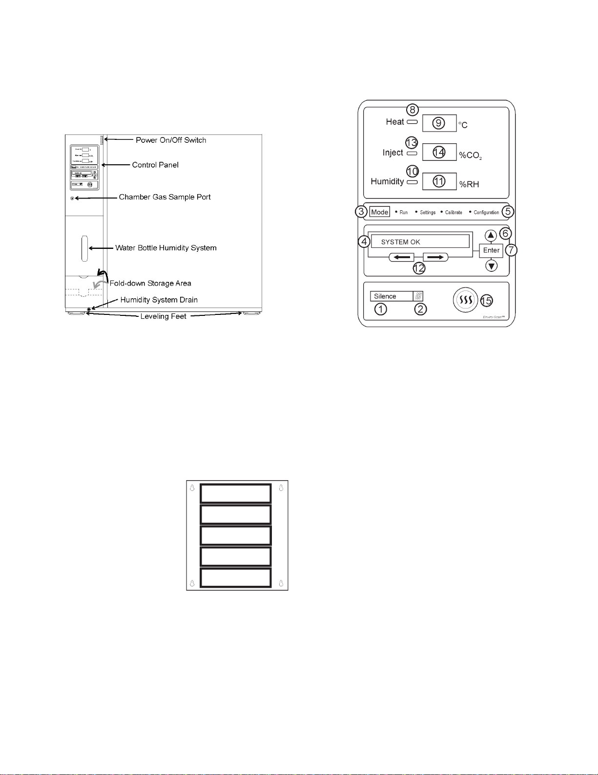
1.1 Incubator Components . . . . . . . . . . . . . . . . . . . . . . . . .1 - 1
1.2 Inventory Management System . . . . . . . . . . . . . . . . .1 - 1
1.3 Control Panel Keys, Displays and Indicators . . . . . . .1 - 1
1.4 Operation of the Keypad . . . . . . . . . . . . . . . . . . . . . . .1 - 2
1.5 Displays . . . . . . . . . . . . . . . . . . . . . . . . . . . . . . . . . . .1 - 2
1.6 Installing the Incubator . . . . . . . . . . . . . . . . . . . . . . . .1 - 2
a. Choosing the Location . . . . . . . . . . . . . . . . . . . . . .1 - 2
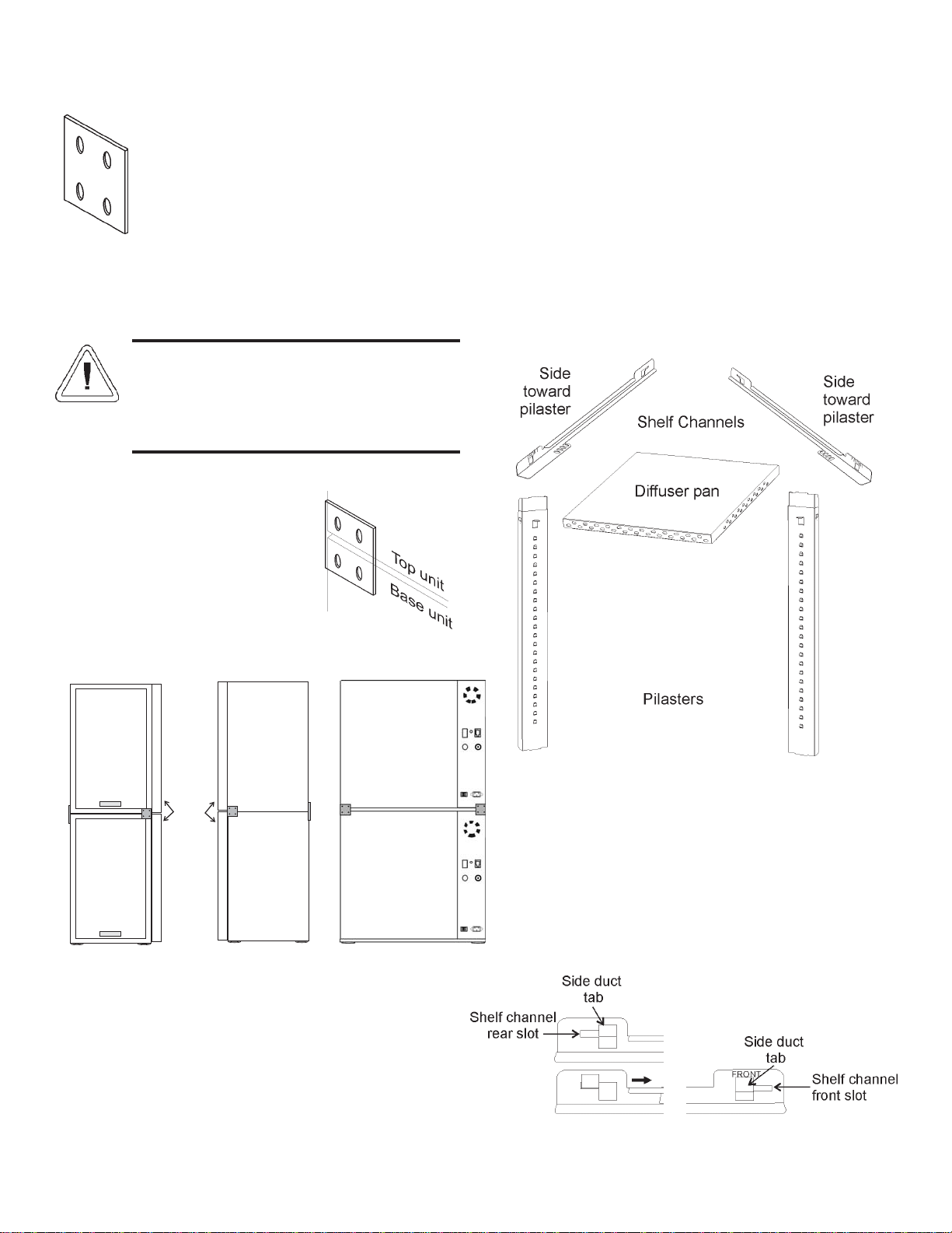
b. Stacking the Incubators . . . . . . . . . . . . . . . . . . . . .1 - 2
c. Preliminary Cleaning . . . . . . . . . . . . . . . . . . . . . . .1 - 3
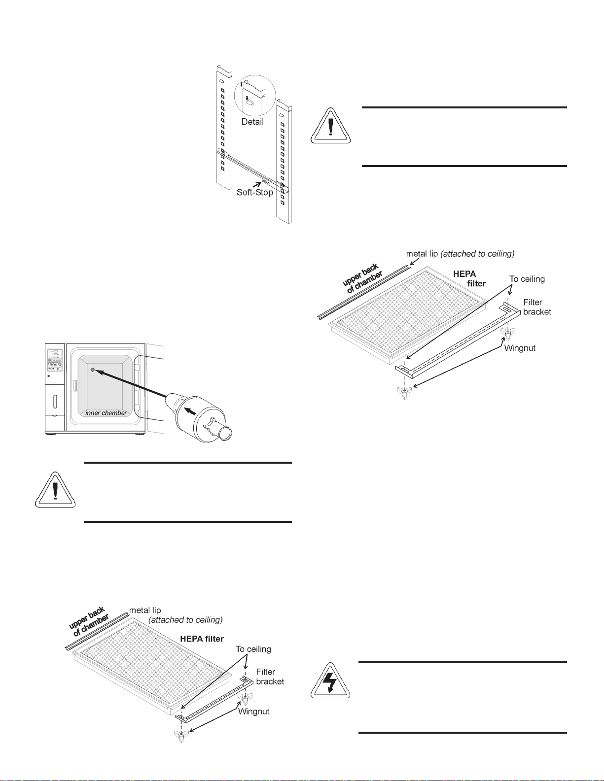
d. Installing the Shelves . . . . . . . . . . . . . . . . . . . . . . .1 - 3
e. Installing the Access Port Filter Assembly . . . . . .1 - 4
f. Installing the HEPA Filter . . . . . . . . . . . . . . . . . . .1 - 4
g. Leveling the Unit . . . . . . . . . . . . . . . . . . . . . . . . . .1 - 4
h. Connecting the Unit to Electrical Power . . . . . . . .1 - 4
i. Filling the Humidity Water Bottle . . . . . . . . . . . . .1 - 5
j. Connecting the CO2Gas Supply . . . . . . . . . . . . . .1 - 5
k. Humidity and Loading the Chamber . . . . . . . . . . .1 - 6
Section 2 - Incubator Settings . . . . . . . . . . . . . . . . . . . . .2 - 1
2.1 Incubator Start-Up . . . . . . . . . . . . . . . . . . . . . . . . . . .2 - 1
a. Setting the Temperature Setpoint . . . . . . . . . . . . . .2 - 1
b. Setting the Overtemp Setpoint . . . . . . . . . . . . . . . .2 - 1
c. Setting the CO2Setpoint . . . . . . . . . . . . . . . . . . . .2 - 1
d. Setting the Relative Humidity (RH) Setpoint . . . . .2 - 1
Section 3 - Calibration . . . . . . . . . . . . . . . . . . . . . . . . . . .3 - 1
3.1 Calibration Mode . . . . . . . . . . . . . . . . . . . . . . . . . . . .3 - 1
a. Calibrating the Temperature . . . . . . . . . . . . . . . . .3 - 1
Temperature Stabilization Periods . . . . . . . . . . . . . . .3 - 1
b. Calibrating the Infrared CO2System . . . . . . . . . . .3 - 1
c. Calibrating Relative Humidity . . . . . . . . . . . . . . . .3 - 1
Section 4 - Configuration . . . . . . . . . . . . . . . . . . . . . . . .4 - 1
4.1 Configuration Mode . . . . . . . . . . . . . . . . . . . . . . . . . .4 - 1
a. Turning the Audible Alarm ON/OFF . . . . . . . . . . .4 - 1
b. New HEPA Filter . . . . . . . . . . . . . . . . . . . . . . . . . .4 - 1
c. Setting the REPLACE HEPA filter reminder . . . .4 - 1
d. Setting an Access Code . . . . . . . . . . . . . . . . . . . . .4 - 1
e. Setting a Low Temperature Alarm Limit . . . . . . . .4 - 2
f. Enabling Temperature Alarms to Trip Contacts . . .4 - 2
g. Setting a Low CO2Alarm Limit . . . . . . . . . . . . . .4 - 2
h. Setting a High CO2Alarm Limit . . . . . . . . . . . . . .4 - 2
i. Enabling CO2Alarms to Trip Contacts . . . . . . . . .4 - 2
j. Setting a Low RH Alarm Limit . . . . . . . . . . . . . . .4 - 2
k. Setting a High RH Alarm Limit . . . . . . . . . . . . . .4 - 3
l. Enabling RH Alarms to Trip Contacts . . . . . . . . . .4 - 3
m. Selecting a Primary Tank w/ Gas Guard Option .4 - 3
n. Disabling the Gas Guard System . . . . . . . . . . . . . .4 - 3
o. Setting a RS485 Communications Address . . . . . .4 - 3
Section 5 - Alarms . . . . . . . . . . . . . . . . . . . . . . . . . . . . . .5 - 1
5.1 Alarms . . . . . . . . . . . . . . . . . . . . . . . . . . . . . . . . . . . . .5 - 1
5.2 Temp Controller Failure TEMP CNTRL ERROR . .5 - 2
5.3 RH System Fault . . . . . . . . . . . . . . . . . . . . . . . . . . . . .5 - 2
5.4 Sensor Fault Alarms . . . . . . . . . . . . . . . . . . . . . . . . . .5 - 2
5.5 Gas Guard Alarms . . . . . . . . . . . . . . . . . . . . . . . . . . . .5 - 2
5.6 Water Level Alarms . . . . . . . . . . . . . . . . . . . . . . . . . .5 - 2
5.7 Doors Open . . . . . . . . . . . . . . . . . . . . . . . . . . . . . . . . .5 - 2
Section 6 - Troubleshooting . . . . . . . . . . . . . . . . . . . . . . .6 - 1
Section 7 - Routine Maintenance . . . . . . . . . . . . . . . . . .7 - 1
7.1 Cleaning the Incubator Interior . . . . . . . . . . . . . . . . . .7 - 1
7.2 Cleaning the Cabinet Exterior . . . . . . . . . . . . . . . . . .7 - 1
7.3 Cleaning the Humidity System . . . . . . . . . . . . . . . . . .7 - 2
7.4 HEPA Filter Maintenance . . . . . . . . . . . . . . . . . . . . . .7 - 2
Section 8 - Sterilization Cycle . . . . . . . . . . . . . . . . . . . . .8 - 1
8.1 Sterilization Cycle . . . . . . . . . . . . . . . . . . . . . . . . . . . .8 - 3
Section 9 - Factory Options . . . . . . . . . . . . . . . . . . . . . . .9 - 1
9.1 Connections to External Equipment . . . . . . . . . . . . . .9 - 1
a. Connecting the Remote Alarm Contacts . . . . . . . .9 - 1
b. Connecting the RS485 Interface . . . . . . . . . . . . . .9 - 1
c. Connecting the Analog Output Boards . . . . . . . . .9 - 1
9.2 CO2Gas Guard . . . . . . . . . . . . . . . . . . . . . . . . . . . . .9 - 2
a. Connecting the CO2Gas Supplies . . . . . . . . . . . . .9 - 2
b. De-activating the Gas Guard . . . . . . . . . . . . . . . . .9 - 2
c. Operation of the CO2Gas Guard . . . . . . . . . . . . . .9 - 3
9.3 Datalogger . . . . . . . . . . . . . . . . . . . . . . . . . . . . . . . . . .9 - 3
Section 10 - Specifications* . . . . . . . . . . . . . . . . . . . . . . .10-1
Section 11 - Servicing . . . . . . . . . . . . . . . . . . . . . . . . . . . .11-1
11.1 Parts List . . . . . . . . . . . . . . . . . . . . . . . . . . . . . . . . . . .11-1
11.2 Replacing the Fuses . . . . . . . . . . . . . . . . . . . . . . . . . .11-2
11.3 Replacing the CO2and RH Air Filters . . . . . . . . . . . .11-2
Appendix A - Class 100 Air
Declarations of Conformity
v

Section 1 - Installation and Start-up
1.1 Incubator Components
Figure 1-1
Steri-Cult Incubator
• Chamber Gas Sample Port - Used for sampling chamber
CO2content using a FYRITE or similar instrument.
• Power On/Off Switch - Mains disconnect
• Control Panel - Keypad, Displays & Indicators (Figure 1-2)
• Fold-down Storage Area - Store manuals, markers, etc.
• Leveling Feet - Used to level the unit
Note: The incubators are stackable. See Section 1.5.b.
1.2 Inventory Management System
Included in the parts bag
shipped with each unit is an invento-
ry management system. This system
consists of:
• A steel plate
• Five different colored magnets
• Five heat-resistant shelf labels
• Dry-Erase marker
Hang the plate on the inside of the outer door, using the
keyholes and hardware already installed on the door. Attach a
colored shelf label to the front edge of each shelf. The magnets
may be aligned on the plate, in order according to shelf label
color. Use the marker to record information about the product
on corresponding shelves. The magnets can be erased as needed
and rewritten.
The inventory management system magnet plate will not
withstand the heat of the sterilization cycle. Simply unhook the
whole plate from the outer door and set aside before initiating
the cycle, then reinstall afterward.
1.3 Control Panel Keys, Displays and Indicators
Figure 1-2
1. Silence - Silences the audible alarm.
2. Alarm Indicator - Light pulses on/off during an alarm
condition in the cabinet.
3. Mode Select Switch - Used to select Run, Setpoints,
Calibration and System Configuration Modes.
4. Message Center - Displays system status.
5. Mode Select Indicators -
Run: Run Menu
Settings: Set Points Menu
Calibrate: Calibration Menu
Configuration: Configuration Menu
6. Up and Down Arrows - Increments number values, tog-
gles between choices.
7. Enter - Stores the value into computer memory.
8. Heat Indicator - Lights when power is applied to the
heaters.
9. Heat Display - Displays temperature (°C)
10. Humidity Indicator - Lights when humidity is required
11. RH Display - Displays humidity (%)
12. Left and Right Arrows - Moves the operator through the
choices of the selected mode.
13. Inject Indicator - Lights when CO2is being injected into
the incubator chamber.
14. CO2Display - Displays CO2(%)
15. Sterilization Button - Starts Sterilization Cycle
Steri-Cult Incubator ____________________________________________________________Installation and Start-Up
1 - 1

1.4 Operation of the Keypad
The Steri-Cult incubator has four basic modes which allow
incubator setup: Run, Settings, Calibrate and System
Configuration.
Run is the default mode which the incubator will normally
be in during operation.
Settings is used to enter system setpoints for incubator
operation.
Calibrate is used to calibrate various system parameters.
Configuration allows for custom setup of various options.
The chart below shows the selections under each of the
Modes. Base Unit Displays are in bold type and Option
Displays are in italics.
Right and Left Arrows: Steps the operator through the
parameters of Settings, Calibrate and Configuration
Modes. The right arrow goes to the next parameter, the
left arrow returns to the previous parameter.
Up Arrow: Increases or toggles the parameter value that
has been selected in the Settings, Calibrate, and
Configuration Modes.
Enter: Must press Enter key to save to memory all
changed values.
Down Arrow: Decreases or toggles the parameter values
that have been selected in the Settings, Calibrate and
Configuration Modes.
Silence Key: Press to silence the audible alarm. See
Section 5 for alarm ringback times.
1.5 Displays
Message Center: Displays the system status (Mode) at all
times. Displays CLASS 100, SYSTEM OK or RH
WAITS ON TEMP (see Setting the RH Setpoint for fur-
ther details) during normal operation. Alarm messages
display if the system detects an alarm condition. See
Section 5, Alarms. The display message CLASS 100 is
a timing mechanism indicating that, under normal oper-
ating conditions with the HEPA filter installed, the air
inside the chamber meets the Class 100 air cleanliness
standard for particulates of 0.5 micron size or larger per
cubic foot of air. (For further information on the Class
100 classification of air quality, see Appendix A.)
3 Upper Displays: The first upper display shows the tem-
perature. The second display shows the percentage of
CO2. The third display shows the humidity percentage.
1.6 Installing the Incubator
a. Choosing the Location
Single and stacked units must be installed against a
wall or similar structure.
1. Maintain a three-inch clearance behind the incubator for
electrical and gas hook-ups. In addition, a three-inch
ventilation space is needed on each side of the unit.
2. Locate the unit on a firm level surface capable of sup-
porting the unit’s weight (340 lbs.-Models 3307 & 3308,
410 lbs.-Models 3310 & 3311)
3. Locate the unit away from doors and windows and heat-
ing and air conditioning ducts.
4. Lift the unit only by the sides of the cabinet base. Do
not attempt to lift it by the front and back. This places
stress on the outer door hinges.
b. Stacking the Incubators
With incubators in a stacked configuration, do not
leave both exterior doors open at the same time.
If the units have been in operation, turn them
both off and disconnect the power before begin-
ning any service work.
Steri-Cult Incubator ____________________________________________________________Installation and Start-Up
1 - 2
Run
Settings
Calibrate
Configuration
Default
Temperature
Temp Cal
Audible
Overtemp
CO2Cal
New HEPA Timer
CO2
RH Cal
Replace HEPA Reminder
RH
Access Code
Temp Lo Alarm
Temp Relay
CO2Lo Alarm
CO2Hi Alarm
CO2Relay
RH Lo Alarm
RH Hi Alarm
RH Relay
Tank Select
Gas Guard
RS485 Address

Four stacking brackets (one shown at left) are
included in the parts bag shipped with each incu-
bator.
Figure 1-3
1. Unscrew and remove the 4 leveling feet from the unit to
be stacked on top and lift it onto the base unit. Align all
sides.
This incubator weighs 340 lbs. for Models 3307 &
3308, 410 lbs. for Models 3310 & 3311. Have suf-
ficient personnel available when lifting. Lift the
unit by the sides of the cabinet base to avoid plac-
ing stress on the outer door hinge.
2. Remove the hole plugs from the stacking bracket holes
(see Figure 1-5).
3. Align the holes in the brackets
with the mounting holes on the
sides of the top and bottom incu-
bator. Secure the two brackets
with the stainless steel screws
and washers provided in the
parts bag. See Figure 1-4.
4. The stacked incubators are ready for service.
c. Preliminary Cleaning
1. Using a suitable laboratory disinfectant, thoroughly
clean all interior surfaces.
d. Installing the Shelves
1. Install the pilasters, two on each side, with the tab facing
into the center of the chamber with their slots up. Press
downward on the top section of each pilaster to locate,
then release when in position (Figure 1-8). Fit each
pilaster securely into the indentations at each side of the
ceiling and the floor of the chamber. Figure 1-6 shows
the diffuser pan, pilasters, and shelf channels.
Note that there is a difference between the left and right shelf
channel. The channels are stamped as to which end goes to the
front of the unit.
2. Install the diffuser pan in the bottom of the unit with the
flanges down. See Section 9 at this point if your unit
includes a factory-installed datalogger (P/N 201912).
3. Install the shelf channels by placing the channel’s rear
slot over the appropriate rear tab on the pilaster. Pull the
shelf channel forward and engage the channel’s front
slot into the pilaster’s appropriate forward tab. Refer to
Figure 1-7.
Steri-Cult Incubator ____________________________________________________________Installation and Start-Up
1 - 3
Figure 1-7
Figure 1-6
Figure 1-4
Door
Sides of stacked units,
brackets installed Back of stacked units,
brackets installed
Figure 1-5

4. Figure 1-8 shows a shelf channel
installed on pilasters on the right
side of the chamber.
5. Slide the shelves in, side flanges
upward, along the channels into the
chamber.
Note: A Soft-Stop indicates the pullout limit
to prevent shelf tipping when fully extend-
ed.
e. Installing the Access Port Filter Assembly
1. Locate the opening in the top left corner on the inside of
the chamber. Remove the tape covering the opening on
the outside of the unit.
2. Install the the stopper assembly into the opening inside
the chamber. See Figure 1-9. Make sure the arrow on the
filter is pointing to the back wall of the chamber.
Filter MUST be installed inside the chamber or it
will become plugged with condensation and inhibit
the recovery of the RH system. Do not replace this
filter with a solid cover of any kind.
f. Installing the HEPA Filter
Use caution when handling the filter. The media
can be damaged if it is mishandled.
To avoid damage to the incubator, do not operate
the unit without the HEPA filter in place.
1. Remove the filter from the shipping box.
2. Remove the plastic covering from the filter, using cau-
tion not to touch the filter media.
3. Loosen black wingnuts in front corners of the chamber
ceiling (Figure 1-10/1-11).
4. Locate the metal lip at the upper back of the chamber.
Hook the HEPA filter carefully over the back edge of the
metal lip.
5. Lift the front of the filter to the ceiling of the chamber.
Push filter bracket back over the filter frame. Tighten the
wingnuts.
6. Refer to Section 6.4 for HEPA filter maintenance.
g. Leveling the Unit
Check for level by placing a bubble-style level on one of
the shelves. Turn the hex nut on the leveling feet counterclock-
wise to lengthen the leg or clockwise to shorten it. Level the
unit front-to-back and left-to-right.
h. Connecting the Unit to Electrical Power
See the serial tag on the side of the unit for electrical speci-
fications or refer to the electrical schematics in this manual.
The serial tag amp rating is based on the amper-
age draw during the sterilization cycle. Normal
operating amperage is much less. Ensure that the
electrical circuit will handle the amp draw of the
sterilization cycle.
Steri-Cult Incubator ____________________________________________________________Installation and Start-Up
Figure 1-8
orientation for
3307/3308
Figure 1-10
1 - 4
orientation for
3310/3311
Access port
filter assembly
Figure 1-9
Figure 1-11

1 - 5
Connect the incubator to a grounded, dedicated
circuit. The power cord connector is the mains
disconnect device for the incubator. Position the
incubator so the unit can be easily disconnected.
Plug the provided power cord into the power inlet connec-
tor on the back of the cabinet (See Figure 1-13), then into the
grounded, dedicated, electrical circuit.
i. Filling the Humidity Water Bottle
1. Open the outer chamber door.
2. Open the access
door located on the
front of the unit,
below the control
board. See Figure
1-12.
3. Remove the lid of
the humidity bottle
and fill with sterile
distilled water.
Install the lid and
close the door,
being careful not to
pinch the tubing.
For best operation of the incubator, sterilized distilled,
demineralized or de-ionized water should be used in the water
bottle. Refer to ASTM Standard D5391-93 or D4195-88 for
measuring water purity.
Distillation systems and reverse osmosis water purity sys-
tems produce water that is neutral in pH (approximately 7) and
is the preferred water to use for humidification. High purity,
ultra pure or milli-q water is considered an aggressive solvent
and slightly acidic. While it may be used, it is not preferred.
Chlorinated tap water, or additives containing chlorine, is not to
be used as chlorine can deteriorate the stainless steel. Tap water
may also have a high mineral content, which would produce a
build-up of scale in the reservoir. Even high purity water can
contain bacteria and organic contaminants. Water should always
be sterilized or treated with a decontaminant, safe for use with
stainless steel as well as safe for the product, prior to being
introduced into the humidity water bottle.
Use of chlorinated water, or decontamination prod-
ucts containing chlorine, will deteriorate the stain-
less steel and cause rust, voiding the warranty.
j. Connecting the CO2Gas Supply
High concentrations of CO2gas can cause asphyx-
iation! OSHA Standards specify that employee
exposure to carbon dioxide in any eight-hour shift
of a 40-hour work week shall not exceed the eight-
hour time weighted average of 5000 PPM (0.5%
CO2). The short term exposure limit for 15 minutes
or less is 30,000 ppm (3% CO2). Carbon dioxide
monitors are recommended for confined areas
where concentrations of carbon dioxide gas can
accumulate.
This incubator is designed to be operated with CO2
gas only. Connecting a flammable or toxic gas can
result in a hazardous condition.
Gases other than CO2should not be connected to
this equipment. CO2gas cylinders have a UN1013
label on the cylinder and are equipped with a CGA
320 outlet valve. Check the gas cylinder for the
proper identification labels. The CO2gas supply
being connected to the incubator should be indus-
trial grade, 99.5% pure (nominal). Do not use CO2
gas cylinders equipped with siphon tubes. A siphon
tube is used to extract liquid CO2from the cylinder
which can damage the pressure regulator. Consult
with your gas supplier to ensure that the CO2
cylinder does not contain a siphon tube. Gas cylin-
ders should also be secured to a wall or other sta-
tionary object to prevent them from tipping.
A two-stage CO2pressure regulator is required to
be installed on the outlet valve of the gas cylinder.
Input pressure to the incubator must be main-
tained at 15 psig (103.4 kPa) for proper perform-
ance of the CO2control system. A single stage CO2
pressure regulator will not maintain 15 psig (103.4
kPa) to the incubator as the pressure in the CO2
cylinder decreases; therefore, a two stage regula-
tor is recommended.
If higher purity CO2is desired inside the incubator
(greater than 99.5% pure nominal), the pressure
regulator should be constructed with a stainless
steel diaphragm, along with specifying the purity
of the CO2from the gas supplier. Follow the man-
ufacturer’s instructions to ensure proper and safe
installation of the pressure regulator on the gas
cylinder.
Consult a facility safety officer to ensure that the
equipment is installed in accordance with codes
and regulations applicable in your area.
Steri-Cult Incubator ____________________________________________________________Installation and Start-Up
Figure 1-12

The CO2gas supply being connected should
be industrial grade 99.5% pure (nominal) and
should not contain siphon tubes. Install a two-stage
pressure regulator at the cylinder outlet. The high
pressure gauge at the tank should have 0-2000
PSIG range. The low pressure gauge, at the incu-
bator inlet, should have a 0-30 PSIG range. Input
pressure to the incubator must be maintained at 15
PSIG (103.4 kPa).
The incubator has serrated fittings on the back
of the cabinet to connect the gas supply. Refer to
Figure 1-13. The fitting is labeled CO2Inlet #1
Tank. Make sure that the connections are secured
with clamps. Check all fittings for leaks.
For units having the CO2Gas Guard option,
refer to Section 8.2.
k. Humidity and Loading the Chamber
With the chamber loaded with liquid product and the RH
setpoint at less than 90%, some evaporation of product will
occur. If the actual RH reaches 2% above setpoint, the incuba-
tor microprocessor turns on dehumidification. This process
pulls outside air in through the nebulizer and exhausts air
through the access port. Humidity decreases. However, in the
process, CO2consumption increases. Ensure your tank and
product are monitored.
1 - 6
Steri-Cult Incubator _________________________________________________________________Installation and Start-Up
Figure 1-13
Power inlet
connector

Section 2 - Incubator Settings
2.1 Incubator Start-Up
With the incubator properly installed and connected to
power, the humidity water bottle filled, and the unit connected
to gas supplies, system setpoints can be entered. The following
setpoints can be entered in Settings mode: Temperature,
Overtemp, CO2and RH. To enter Settings mode, press the
Mode key until the Settings indicator lights. Press the right
and/or left arrow keys until the proper parameter appears in the
message center. See Chart 2-1 for more detail.
a. Setting the Temperature Setpoint
The temperature setpoint range is 10°C to 50°C, settable to
within 0.1°C. The lowest temperature the incubator can control
is +5°C above the ambient temperature in the incubator’s loca-
tion. The incubator is shipped from the factory with a tempera-
ture setpoint of 10°C. At this setting, temperature control and
alarms are turned off. To change the temperature setpoint:
1. Press the Mode key until the Settings indicator lights.
2. Press the right arrow until “Temp XX.XC” is displayed
in the message center.
3. Press the up/down arrow key until the desired tempera-
ture setpoint is displayed.
4. Press Enter to save the setpoint.
5. Press the Mode key until the Run indicator lights for
Run mode or press the right/left arrow keys to go to
next/previous parameter.
b. Setting the Overtemp Setpoint
The independent overtemp system is designed as a
safety to protect the incubator only. It is not
intended to protect or limit the maximum tempera-
ture of the cell cultures or customer’s equipment
inside the incubator if an overtemp condition
occurs.
The Steri-Cult incubators are equipped with a secondary
temperature monitoring system to monitor the air temperature
inside the cabinet. This system is designed as a safety device to
turn off all heaters in the event of a temperature control failure.
Temperature control in the incubator will be ±1° of the
overtemp setpoint.
The overtemperature is set by the factory (default) at 40°C.
However, the overtemp can be set up to 55°C in 0.1° incre-
ments.
If the incubator’s operating temperature setpoint is set
above the overtemp setpoint, the overtemp setpoint will auto-
matically update to 1°C above the temperature setpoint. 2 - 1
It is recommended that the overtemp setpoint be main-
tained at 1°C over the operating temperature setpoint.
To change the Overtemp setpoint:
1. Press the Mode key until the Settings indicator lights
2. Press the right arrow until OVERTEMP XX.XC is dis-
played in the message center
3. Press the up or down arrow key until the desired
Overtemp setpoint is displayed
4. Press Enter to save the setting
5. Press the Mode key until the Run indicator lights or
press the right or left arrow to go to the next or previous
parameter.
c. Setting the CO2Setpoint
The CO2setpoint range is 0.0% to 20.0%, settable to within
0.1% CO2. The incubator is shipped from the factory with a
CO2setpoint of 0.0%. At this setting, all CO2control and
alarms are turned off. To change the CO2setpoint:
1. Press the Mode key until the Settings indicator lights.
2. Press the right arrow until “CO2 XX.X%” is displayed
in the message center.
3. Press the up/down arrows until the desired CO2setpoint
is displayed.
4. Press Enter to save the setpoint.
5. Press the Mode key until the Run indicator lights to go
to Run mode or press the right/left arrow keys to go to
next/previous parameter.
d. Setting the Relative Humidity (RH) Setpoint
The RH setpoint range is 0% to 95%, settable to within 1%
RH. (Settings above 90% may cause some condensation to
occur in the chamber.) The incubator is shipped from the facto-
ry with an RH setpoint of 0%. At this setting, all RH control,
water level control and alarms are turned off. To change the
RH setpoint:
1. Press the Mode key until the Settings indicator lights.
2. Press the right arrow until “RH XX%” is displayed in
the message center.
3. Press the up/down arrows until the desired RH setpoint
is displayed.
4. Press Enter to save the setpoint.
5. Press the Mode key until the Run indicator lights to go
to Run mode or press the right/left arrow keys to go to
next/previous parameter.
On power-up or a temperature setpoint change, RH is
delayed until the temperature is within 0.5°C of the setpoint.
RH WAITS ON TEMP is displayed until this temperature is
reached.
Steri-Cult Incubator ______________________________________________________________________Incubator Settings

Steri-Cult Incubator ______________________________________________________________________Incubator Settings
2 - 2

Section 3 - Calibration
3.1 Calibration Mode
After the unit has stabilized, several different systems can
be calibrated. In Calibration mode, the air temperature, CO2
and RH levels can be calibrated to reference instruments. To
access Calibration mode, press the Mode key until the Calibrate
indicator lights. Press the right and/or left arrow until the
appropriate parameter appears in the message center. See Chart
2-1 at the end of this section for more detail.
Calibration frequency is dependent on use, ambient condi-
tions and accuracy required. A good laboratory practice would
require at least an annual calibration check. On new installa-
tions, all parameters should be checked after the stabilization
period.
Prior to calibration, the user should be aware of the follow-
ing system functions. While the unit is in Calibration mode, all
system control functions are disabled so the unit remains stable.
Readout of the system being calibrated will appear on the mes-
sage center. If no keys are pressed for approximately five min-
utes while in Calibration mode, the system will reset to Run
mode so control functions are reactivated.
Before making any calibration or adjustments to
the unit, it is imperative that all reference instru-
ments be properly calibrated.
a. Calibrating the Temperature
Before calibration, allow the cabinet temperature to stabi-
lize. Place the calibrated instrument in the center of the cham-
ber. The instrument should be in the airflow, not against the
shelf.
Temperature Stabilization Periods
Startup - Allow 12 hours for the temperature in the cabinet to
stabilize before proceeding.
Presently Operating - Allow at least 2 hours after the display
reaches setpoint for temperature to stabilize before proceeding.
1. Press the Mode key until Calibrate indicator lights.
2. Press the right arrow until “TEMP CAL XX.XC”
appears in the message center.
3. Press up/down arrow to match display to calibrated
instrument.
4. Press Enter to store calibration.
5. Press the Mode key to return to Run or the right/left
arrow to go to next/previous parameter. 3 - 1
b. Calibrating the Infrared CO2System
All models of the Steri-Cult incubator have an infrared (IR)
CO2sensor. Infrared CO2sensors are not effected by chamber
atmosphere temperature or humidity.
CO2Sensor Stabilization Times
Start-Up- Allow the CO2of the cabinet to stabilize at least 12
hours before proceeding.
Presently Operating - Allow CO2to stabilize at least 2 hours
at setpoint before proceeding.
1. Measure the CO2concentration in the chamber through
the gas sample port with a Fyrite or other independent
instrument. Several readings should be taken to ensure
accuracy.
2. Press the Mode key until the Calibrate indicator lights.
3. Press the right arrow until “CO2 CAL XX.X%” appears
in the message center.
4. Press the up/down arrow to adjust the display to match
the independent instrument reading.
5. Press Enter to store the calibration.
6. Press the Mode key to return to Run mode.
c. Calibrating Relative Humidity
Place an accurate independent instrument in the center of
the chamber. Most RH measuring devices are least accurate
above 90%. It is recommended that when calibrating above
90%, the incubator should be adjusted to the lower edge of the
instrument accuracy range. For example; with the incubator set
at 95%, the independent instrument with accuracy of ±5% reads
94%. Calibrate the incubator display to 99%. (This prevents
condensation issues caused by actual RH levels above 95%.)
Relative Humidity Stabilization Times
Start-Up - Allow 12 hours for the relative humidity and tem-
perature in the chamber to stabilize before proceeding.
Presently Operating - Allow at least 2 hours after temperature
display reaches setpoint for relative humidity to stabilize before
proceeding.
1. Press the Mode key until the Calibrate indicator lights.
2. Press the right arrow key until “RH CAL XXX%”
appears in the message center.
3. Press the up/down arrow to match the display to the
independent instrument.
4. Press Enter to store the calibration.
5. Press the Mode key to return to Run mode.
Steri-Cult Incubator _________________________________________________________________________Calibration

Steri-Cult Incubator ________________________________________________________________________Calibration
3 - 2

c. Setting the REPLACE HEPA filter reminder
A HEPA filter replacement timer can be set for a specific
amount of time, from 1 to 12 months of actual unit running
time. Time will not accrue when the unit is turned off. The
default time is 6 months. When the allotted time has run out,
REPLACE HEPA appears in the display and the visual alarm
flashes. To set the reminder, use the following procedure.
1. Press the Mode key until the Configuration indicator
lights.
2. Press the right arrow until REPLACE HEPA XX is dis-
played.
3. Press the up/down arrow to choose the number of
months desired.
4. Press Enter to save the number.
5. Press the Mode key to return to Run Mode or right/left
to go to next/previous parameter.
Note: After the reminder has been set, check the allotted time
remaining by going to Configuration mode, then pressing the
right arrow until NEW HEPA XXX displays. This number is
the remaining days before the filter replacement time specified
runs out. For example, if 12 months was chosen in the
REPLACE HEPA XX message screen, the NEW HEPA number
would be 365 days.
d. Setting an Access Code
A 3-digit Access Code can be entered to avoid unautho-
rized personnel from changing the setpoints, calibration, or con-
figuration. A setting of 000 disables the access code function.
The factory setting is 000.
1. Press the Mode key until the Configuration indicator
lights.
2. Press the right arrow until ACCESS CODE XXX is dis-
played in the message center.
3. Press up/down arrow to change the access code.
4. Press Enter to save the access code.
5. Press the Mode key to return to the Run mode or
right/left to go to next/previous parameter.
Section 4 - Configuration
4.1 Configuration Mode
Several features available in the Configuration Mode allow
custom setup of the incubator. These features are listed and
described below. All features may not be necessary in all appli-
cations, but are available if needed. To enter Configuration
mode, press the Mode key until the Configuration indicator
lights. Press the right and/or left arrow until the appropriate
parameter appears in the message center. See Chart 4-1 for
more detail.
a. Turning the Audible Alarm ON/OFF
The audible alarm can be turned on or off. The factory set-
ting is ON.
1. Press the Mode key until the Configuration indicator
lights.
2. Press the right arrow until AUDIBLE ON/OFF is dis-
played in the message center.
3. Press up/down arrow to toggle ON or OFF.
4. Press Enter to save the setting.
5. Press the Mode key to return to Run mode or right/left
to go to next/previous parameter.
b. New HEPA Filter
When the REPLACE HEPA reminder is displayed and the
visual alarm flashes, the specified time has elapsed and the
HEPA filter should be replaced.
After replacing the HEPA filter with a new one, clear the
display and reset the timer by following the steps below.
1. Press the Mode key until the Configuration indicator
lights.
2. Press the right arrow until NEW HEPA XXX is dis-
played in the message center.
3. Press Enter to restart the timer and clear the REPLACE
HEPA alarm.
4. Press the Mode key to return to Run mode.
Steri-Cult Incubator ______________________________________________________________________Configuration
4 - 1

h. Setting a High CO2Alarm Limit (tracking alarm)
The high CO2alarm limit is the deviation from the CO2set-
point which will cause a high CO2alarm. The setpoint is vari-
able from 0.5% to 5.0% CO2above setpoint. The factory set-
ting is 1.0% CO2above setpoint. When activated, the CO2valve
is disabled.
1. Press the Mode key until the Configuration indicator
lights.
2. Press the right arrow until CO2 HI LMT X.X is dis-
played in the message center.
3. Press up/down arrow to change the high CO2alarm
limit.
4. Press Enter to save the high CO2alarm limit.
5. Press the Mode key to return to run mode or right/left to
go to next/previous parameter.
i. Enabling CO2Alarms to Trip Contacts
High and Low CO2alarms can be programmed to trip the
remote alarm contacts. A setting of ON activates this ability. A
setting of OFF will not allow CO2alarms to trip the contacts.
The factory setting is ON.
1. Press the Mode key until the Configuration indicator
lights.
2. Press the right arrow until CO2 RELAY ON/OFF is dis-
played in the message center.
3. Press up/down arrow to toggle the setting ON or OFF.
4. Press Enter to save the setting.
5. Press the Mode key to return to Run mode or right/left
to go to next/previous parameter.
j. Setting a Low RH Alarm Limit (tracking alarm)
The low RH alarm limit is the deviation from the humidity
setpoint which causes a low RH alarm. The setpoint is variable
from -5 to -20% RH. The factory setting is -10%RH.
1. Press the Mode key until the Configuration indicator
lights.
2. Press the right arrow until RH LO LMT -XX is dis-
played in the message center.
3. Press up/down arrow to change the RH low alarm limit.
4. Press Enter to save the RH low alarm limit.
5. Press the Mode key to return to Run mode or right/left
to go to next/previous parameter.
e. Setting a Low Temperature Alarm Limit
(tracking alarm)
The low temperature alarm limit is the deviation from the
temperature setpoint which causes a low temp alarm. The low
temp alarm is variable from one-half degree to five degrees
below setpoint. The factory setting is 1° below setpoint. A
minus sign (-) in the display indicates that the alarm setting is
below the setpoint.
1. Press the Mode key until the Configuration indicator
lights.
2. Press the right arrow until TEMP LO LMT -X.X is dis-
played in the message center.
3. Press up/down arrow to change the low temp alarm
limit.
4. Press Enter to save the low temp alarm limit.
5. Press the Mode key to return to Run mode or right/left
to go to next/previous parameter.
f. Enabling Temperature Alarms to Trip Contacts
The high and low temperature alarms can be programmed
to trip the remote alarm contacts. A setting of ON activates this
ability. A setting of OFF will not allow the temp alarms to trip
the contacts. The factory setting is ON.
1. Press the Mode key until the Configuration indicator
lights.
2. Press the right arrow until TEMP RELAY ON/OFF is
displayed.
3. Press the up/down key to toggle the setting ON/OFF.
4. Press Enter to save the setting
5. Press the Mode key to return to Run or the right/left
arrow key to go to next/previous parameter.
g. Setting a Low CO2Alarm Limit (tracking alarm)
The low CO2alarm limit is the deviation from the CO2set-
point which will cause a low CO2alarm. The setpoint is vari-
able from 0.5% to 5.0% CO2below setpoint. The factory set-
ting is 1.0% CO2below setpoint. A minus sign (-) in the display
indicates that the alarm setting is below the setpoint.
1. Press the Mode key until the Configuration indicator
lights.
2. Press the right arrow until CO2 LO LMT -X.X is dis-
played in the message center.
3. Press up/down arrow to change the low CO2alarm limit.
4. Press Enter to save the low CO2alarm limit.
5. Press the Mode key to return to Run mode or right/left
to go to next/previous parameter.
Steri-Cult Incubator ______________________________________________________________________Configuration
4 - 2

k. Setting a High RH Alarm Limit (tracking alarm)
The high RH alarm limit is the deviation from the humidity
setpoint which causes a high RH alarm. The setpoint is vari-
able from 5 to 20% RH The factory setting is 10% RH. When
the alarm is activated, the humidity system is disabled.
1. Press the Mode key until the Configuration indicator
lights.
2. Press the right arrow until RH HI LMT XX is displayed
in the message center.
3. Press up/down arrow to change the RH high alarm limit.
4. Press Enter to save the RH high alarm limit.
5. Press the Mode key to return to Run mode or right/left
to go to next/previous parameter.
l. Enabling RH Alarms to Trip Contacts
The high and low RH alarms can be programmed to trip
the remote alarm contacts. A setting of ON activates this abili-
ty. A setting of OFF will not allow the RH alarm to trip the con-
tacts. The factory setting is ON.
1. Press the Mode key until the Configuration indicator
lights.
2. Press the right arrow until RH RELAY ON/OFF is dis-
played in the message center.
3. Press up/down arrow to toggle the setting ON or OFF.
4. Press Enter to save the setting.
5. Press the Mode key to return to Run mode or right/left
to go to next/previous parameter.
m. Selecting a Primary Tank w/ Gas Guard Option
On units equipped with the Gas Guard option, a primary
tank can be selected. The primary tank will be either Tank 1 or
2. The factory setting is Tank1.
1. Press the Mode key until the Configuration indicator
lights.
2. Press the right arrow until TANK SELECT X is dis-
played in the message center.
3. Press up/down arrow to toggle setting between 1 and 2 .
4. Press Enter to save the setting.
5. Press the Mode key to return to Run mode or right/left
to go to next/previous parameter.
Steri-Cult Incubator ______________________________________________________________________Configuration
4 - 3
n. Disabling the Gas Guard System
On units equipped with the Gas Guard option, the Gas
Guard system may be turned ON or OFF if it is not in use. The
factory setting is ON.
1. Press the Mode key until the Configuration indicator
lights.
2. Press the right arrow until GAS GUARD ON/OFF is
displayed in the message center.
3. Press up/down arrow to toggle the setting ON or OFF.
4. Press Enter to save the setting.
5. Press the Mode key to return to Run mode or right/left
to go to next/previous parameter.
o. Setting a RS485 Communications Address
(1535 compatible only)
On units that have the RS485 option, direct communication
with the Model 1535 alarm system can be established. Each
piece of equipment connected to the Model 1535 must have a
unique address. An address of 0-24 can be entered for the incu-
bator. A setting of 0 is an invalid address that the 1535 will
ignore. The factory setting for the RS485 address is 0.
1. Press the Mode key until the Configuration indicator
lights.
2. Press the right arrow until 485 ADDRESS XX is dis-
played in the message center.
3. Press up/down arrow to move the RS485 address.
4. Press Enter to save the RS485 address.
5. Press the Mode key to return to Run mode or right/left
to go to next/previous parameter.

Steri-Cult Incubator _______________________________________________________________________Configuration
4 - 4
This manual suits for next models
3
Table of contents
Other Thermo Accessories manuals