Thermo Ramsey Micro-Tech 3000 Series User manual

Serial Communications Manual
Ramsey
Micro-Tech3000
Model 3104
Loss in Weight Controller
Serial Comm-
3104 Rev
Part No.: XXXXX


Ramsey
Micro-Tech
3000
Serial Communications
Model 3104
Loss in Weight Controller
This document is confidential and is the property of Thermo Electron. It may not be
copied or reproduced in any way without the express written consent of Thermo
Electron. This document also is an unpublished work of Thermo Electron. Thermo
Electron intends to, and is maintaining the work as confidential information. Thermo
Electron also may seek to protect this work as an unpublished copyright. In the event
of either inadvertent or deliberate publication, Thermo Electron intends to enforce its
rights to this work under the copyright laws as a published work. Those having
access to this work may not copy, use, or disclose the information in this work unless
expressly authorized by Thermo Electron.
All registered and unregistered trademarks are the property of their respective
owners.
Thermo Electron,
501 90th Avenue N.W.
Minneapolis, MN 55433 U.S.A.
Tel (763) 783-2500
Fax (763) 783-2525
http://www.thermoelectron.com
eng@thermoelectron.com
2003 Thermo Electron

Revision History
Preliminary December 2003 Manual first released

Serial Communications 3104
REC XXXXX i
Table of Contents
Table of Contents ......................................................................................................................i
List of Figures ..........................................................................................................................iii
List of Tables ...........................................................................................................................iv
Chapter 1 Introduction ..................................................................................................... 1-1
1.1 General................................................................................................................... 1-1
1.2 Communication Protocols...................................................................................... 1-1
1.2.1 Protocol Rules ................................................................................................ 1-2
1.3 Printer..................................................................................................................... 1-3
1.4 Thermo Electron Warranty..................................................................................... 1-3
Disclaimer.......................................................................................................................... 1-4
Chapter 2 Installation....................................................................................................... 2-1
2.1 General................................................................................................................... 2-1
2.2 Comm A Board (Option) Installation...................................................................... 2-1
2.3 Communication Configuration (Mother Board) COMM1 ....................................... 2-6
Chapter 3 Operation ........................................................................................................ 3-1
3.1 General................................................................................................................... 3-1
3.2 Printer Scroll........................................................................................................... 3-1
3.3 Print Formats.......................................................................................................... 3-1
3.3.1 Totals .............................................................................................................. 3-2
3.3.2 Batch ............................................................................................................... 3-2
3.3.3 Alarms ............................................................................................................. 3-3
3.3.4 Audit Trails ...................................................................................................... 3-3
3.4 Communication Set-Up.......................................................................................... 3-3
3.4.1 Clock/Calendar Set-Up................................................................................... 3-4
3.4.2 COMM A and Print Scroll Set-Up ................................................................... 3-5
3.4.3 Multidrop Operator Set-Up ............................................................................. 3-7
3.4.4 Printer Set-Up ................................................................................................. 3-8
3.4.5 Define Printing Format.................................................................................. 3-10
3.5 Communication Protocols.................................................................................... 3-14
3.5.1 Registers Definition....................................................................................... 3-15
3.5.2 Type, Limits and Format of Register ............................................................ 3-16
3.5.3 Decription of Register ...................................................................................3-17
3.6 PC-Master Protocol.............................................................................................. 3-25
3.6.1 Description .................................................................................................... 3-25
3.7 Siemens 3964R.................................................................................................... 3-28
3.7.1 Write Register ............................................................................................... 3-28
3.7.2 Read Register ............................................................................................... 3-29
3.8 Modbus................................................................................................................. 3-30
3.8.1 Read Register ............................................................................................... 3-30
3.9 Allen Bradley DF1 (PLC-5) .................................................................................. 3-32

Serial Communications 3104
REC XXXXXii
3.9.1 Read Registers ............................................................................................. 3-32
3.9.2 Write Registers ............................................................................................. 3-33
3.10 Register Mapping ............................................................................................. 3-35
Chapter 4 Maintenance ................................................................................................... 4-1
4.1 General................................................................................................................... 4-1
Chapter 5 Parts................................................................................................................ 5-1
5.1 General................................................................................................................... 5-1

Serial Communications 3104
REC XXXXX iii
List of Figures
Figure 2-1 COMM A Board 2-2
Figure 2-2 Micro-Tech 3000 Mother Board 2-3
Figure 2-3 Serial Connection RS232 2-4
Figure 2-4 Serial Connection RS485 2-5
Figure 2-5 Mother Board Area of Detail 2-8

Serial Communications 3104
REC XXXXXiv
List of Tables
Table 2-1: COMM A Board Jumpers 2-1
Table 2-2: Mother Board COMM1 Communications Wiring Config. TB3–RS485 2-6
Table 2-3: Mother Board Wiring Configuration TB3-RS232 Communications 2-6
Table 2-4: Mother Board Wiring Configuration TB3-20mA Serial Communications 2-7
Table 2-5: Mother Board Communication Jumper Setting 2-7

Serial Communications 3104
REC XXXXX 1-1
Chapter 1 Introduction
1.1 General
The Micro-Tech 3104 is a bus-based microprocessor instrument equipped with one
COMM A (on Mother Board) that can be equipped (optionally) with a second serial
communication boards. Each COMM A board has one serial channel that can be
configured according to the following standards.
!RS423/RS232C For point to point asynchronous bidirectional
communications, maximum 50 feet (15 m). Modem
capability.
!RS485/RS422 For point to point or multidrop 4 wire bidirectional
communications, maximum 4000 feet (1200 m).
!Current Loop For high immunity bidirectional asynchronous
communications. Passive only.
All of the above are optically isolated.
COMM A board (Optionally) can be installed in any available mother board expansion
slot. After installing the board and power has been restored, the instrument
automatically detects the new board and adds the communication set-up scrolls to
the Main Menu scrolls. The Micro-Tech refers to the COMM A on the Mother Board
as COM 1, and the COMM A board (if installed) as COM 2.
If two COMM A are availables; one can be set up for printing, the other one for
transferring data to and from other intelligent devices such as computers and PLC's.
The system cannot support two printers or two COMM lines.
Each COMM A contains a perpetual clock/calendar circuit with battery backup. The
battery is located on the mother board and is the same battery used for system
memory backup. The system automatically detects and uses the clock calendar
circuit of the first board and ignores the second.
Time and date set-up screens become visible after the COMM board is installed.
The Micro-Tech 3000 Integrator COMM meets the year 2000 requirements.
1.2 Communication Protocols
When a COMM line is set up for communication (not for a printer), the system is able
to send and receive data to and from another device connected to the COMM line.
The COMM option comes with the following software communication protocols
already built in:
- PC-Master A Thermo Ramsey proprietary protocol, multidrop.
- Modbus An AEG proprietary protocol, multidrop. The COMM option only
contains a subset of the protocol as specified in this manual.
- Allen-Bradley A proprietary protocol, multidrop. The COMM option only contains
a subset of the protocol in the PLC-5 version of it, as specified in
this manual.
- 3964R A Siemens proprietary protocol, single point.

Serial Communications 3104
REC XXXXX1-2
The hardware can be configured (through jumpers on the Mother Board and on the
optinally COMM board if available) to one of the three standards as listed in the
previous paragraph. However, only the RS485/RS422 standard allows multidrop
communications, RS232C and Current Loop can only be used in point to point mode.
This does not prevent the use of a protocol; it only prevents physically connecting the
Micro-Tech 3000 to more than one device.
CAUTION
The communication protocols have been implemented and tested as
described in this document or in other referenced documents. It is
the intention of Thermo Ramsey to provide all the necessary
information and help the user to connect the instrument to other
compatible devices. However, because most of the protocols are
specific to other manufacturers, Thermo Ramsey declines any
responsibility for any malfunction that may occur when connecting
the instrument to devices of other manufacturers, unless tested and
approved by Thermo Ramsey.
1.2.1 Protocol Rules
The communication protocol allows a remote intelligent device to read and
eventually write information from and to the Micro-Tech 3104. For
convenience, the information is organized in a set of registers as listed in this
document.
During the communication activity, the Micro-Tech 3104 always acts as Slave,
meaning it responds to a request from a Master device on the line, but never
attempts to send messages out.
The following rules apply:
a. The Micro-Tech 3104 responds only if the message is completely
received.
b. The Micro-Tech 3104 reads the message and looks for the address,
which is contained into an address byte in the query package. The
message is then processed only if the address matches the one specified
in the set-up data of the Micro-Tech 3104, otherwise it is ignored.
c. When the system receives a message, the integrity of the message is
checked. An answer-back message is prepared if the message is
formally correct.
d. When a message containing a variable to be written in memory is
received, the system checks the correctness of the message and, if it is
correct, immediately sends the answer-back message. This does not
always mean the data is written in memory. The system first checks the
register number (which must correspond to a valid address of a variable),
then the minimum and maximum limits, and then the password. If data
can be accepted, it is stored in memory and the success flag is set to 0
(no error). If not, it is set to 1. To know if the last variables sent have
been stored, the Master checks (reads) the success flag contained in a
read only register.
The following procedure applies:
- The Host sends data to the Micro-Tech 3104.

Serial Communications 3104
REC XXXXX 1-3
- The Host waits at least 100 ms.
- The Host reads the success flag. It should be 0.
Some data is read only, some is read write, and some is write only.
WARNING
In all cases, the maximum number of words the system can transfer
is limited to 41 per time. Requests of registers in excess of 41 are
considered errors and do not generate an answer.
1.3 Printer
When a COMM line is set up for printing, the system prints out data in different ways,
depending on the set-up. Print menus become visible that allow the user to define
when and in which format the data is printed.
1. Periodical printouts at predefined intervals, as well as at predefined times of
day, or on command is possible.
2. The format of the printouts is selectable between a number of predefined
formats, plus a fully programmable user defined format. In this particular case,
the user is able to easily format the printout to fit into any pre-printed ticket or
form, without the need of special software.
1.4 Thermo Electron Warranty
The seller agrees, represents, and warrants that the equipment delivered
hereunder shall be free from defects in material and workmanship. Such
warranty shall not apply to accessories, parts, or material purchased by the
seller unless they are manufactured pursuant to seller's design, but shall apply
to the workmanship incorporated in the installation of such items in the complete
equipment. To the extent purchased parts or accessories are covered by the
manufacturer's warranty, seller shall extend such warranty to buyer.
Seller's obligation under said warranty is conditioned upon the return of the
defective equipment, transportation charges prepaid, to the seller's factory in
Minneapolis, Minnesota, and the submission of reasonable proof to seller prior
to return of the equipment that the defect is due to a matter embraced within
seller's warranty hereunder. Any such defect in material and workmanship shall
be presented to seller as soon as such alleged errors or defects are discovered
by purchaser and seller is given opportunity to investigate and correct alleged
errors or defects and in all cases, buyer must have notified seller thereof within
one (1) year after delivery, or one (1) year after installation if the installation was
accomplished by the seller.
Said warranty shall not apply if the equipment shall not have been operated and
maintained in accordance with seller's written instructions applicable to such
equipment, or if such equipment shall have been repaired or altered or modified
without seller's approval; provided, however, that the foregoing limitation of
warranty insofar as it relates to repairs, alterations, or modifications, shall not be
applicable to routine preventive and corrective maintenance which normally
occur in the operation of the equipment.

Serial Communications 3104
REC XXXXX1-4
“EXCEPT FOR THOSE WARRANTIES SPECIFICALLY CONTAINED HEREIN,
SELLER DISCLAIMS ANY AND ALL WARRANTIES WITH RESPECT TO THE
EQUIPMENT DELIVERED HEREUNDER, INCLUDING THE IMPLIED
WARRANTIES OF MERCHANTABILITY AND FITNESS FOR USE. THE SOLE
LIABILITY OF SELLER ARISING OUT OF THE WARRANTY CONTAINED
HEREIN SHALL BE EXCLUSIVELY LIMITED TO BREACH OF THOSE
WARRANTIES. THE SOLE AND EXCLUSIVE REMEDY FOR BREACH OF
THE WARRANTIES SET OUT ABOVE SHALL BE LIMITED TO THE REPAIR
OR REPLACEMENT OF ANY DEFECTIVE ACCESSORY, PART OR
MATERIAL WITH A SIMILAR ITEM FREE FROM DEFECT, AND THE
CORRECTION OF ANY DEFECT IN WORKMANSHIP. IN NO EVENT SHALL
SELLER BE LIABLE FOR ANY INCIDENTAL OR CONSEQUENTIAL
DAMAGES.”
Purchaser agrees to underwrite the cost of any labor required for replacement;
including time, travel, and living expenses of Thermo Electron Field Service
Engineer at closest factory base.
THERMO ELECTRON
501 90TH AVE. NW
MINNEAPOLIS, MN 55433
PHONE: (763) 783-2500
FAX: (763) 783-2525
Disclaimer
Though the information provided herein is believed to be accurate, be advised
that the information contained herein is not a guarantee for satisfactory results.
Specifically, this information is neither a warranty nor guarantee, expressed or
implied, regarding performance, merchantability, fitness, or any other matter
with respect to the products, and recommendation for use of the product/process
information in conflict with any patent. Please note that Thermo Electron
reserves the right to change and/or improve the product design and
specifications without notice.

Serial Communications 3104
REC XXXXX 2-1
Chapter 2
Installation
2.1 General
This chapter describes the installation procedure and hardware configuration for the
communications (on Mother Board and on Comm A Board option). If the
communication option was installed at the factory, it may not be necessary to
continue with this chapter. Proceed to Chapter 3.0, Operation.
2.2 Comm A Board (Option) Installation
To install the COMM A board, proceed as follows:
1. Select the jumper positions on the COMM A board for the desired
communication standard. Below is a table which summarizes the jumper
positions for selection of the electrical interface. Refer to Figure 2-1 for jumper
locations.
TABLE 2-1
COMM A BOARD JUMPERS
JUMPERS
Mode
OP1
OP2
OP3
OP4
OP5
OP6
RS-232
"A"
"A"
"A"
"A"
"A"
"B"
RS-485
"B"
"A"
"B"
"B"
"MDP"
"TRM"
[Default)
20 mA
"B"
"B"
"A"
"A"
"A"
"C"
TABLE "MDP" TABLE "TRM"
FOR RS-485 ONLY FOR RS-485 ONLY
OP5 OP6
"A" NORMAL "A" TERMINATED
"B" MULTIDROP "B" NOT TERMINATED
2. Open the Micro-Tech wall mount enclosure and turn power off at the mains,
or remove panel mount enclosure from the panel and remove top cover
allowing access to the mother board.
3. Remove the field mating connector. Wire the connector per the supplied
field wiring diagram or install field terminal board cable (wall mount only).
4. Remove the hex head mounting screw from the connector end of the COMM
board.
5. Insert the COMM board in any available expansion slot on the mother board
(see Figure 2-2).

Serial Communications 3104
REC XXXXX2-2
Figure 2-1 COMM A Board

Serial Communications 3104
REC XXXXX 2-3
-SLOT # N CHANGED
Acquire new
configuration?
YES NO
Figure 2-2 Micro-Tech 3000 Mother Board
EXPANSION
SLOT
6. Insert the hex head screw through the chassis and tighten.
7. Install the wired mating connector on the COMM board connector.
8. Reinstall panel mount enclosure in the panel.
9. Turn power back on. The following screen appears when power is applied
and remains on for 10 seconds.
The screen disappears after 10 seconds if the question is not answered, and
the Micro-Tech 3104 assumes the answer is NO. "HW CONFIG. CHANGED"
alarm is on and cannot be reset. The above screen appears each time power
is cycled if the question is not answered.
Answer YES because this is a hardware configuration change.
10. This completes the installation procedure.
11. Set-up data for the newly installed COMM board must now be
entered. Proceed to Chapter 3.0, Operation.

Serial Communications 3104
REC XXXXX2-4
Figure 2-3 Serial Connection RS232

Serial Communications 3104
REC XXXXX 2-5
Figure 2-4 Serial Connection RS485

Serial Communications 3104
REC XXXXX2-6
2.3 Communication Configuration (Mother Board) COMM1
This section describes the setup procedure and hardware configuration for the
communications from the motherboard. Use the following steps to configure
the communications:
Select the jumper positions for the desired communication standard. Refer to
Table 2-5 for jumper locations.
Wire to the Terminal Block 3 on the motherboard for the communication
standard selected, RS-485, RS-232c, 20 mA current loop.
Table 2-2: Mother Board COMM 1 Communications Wiring Configuration - TB3 – RS-485
Motherboard
RS-485 Communications
TB 3
25 Shield
29 -RX
28 +Rx
24 Common
21 +TX
20 -TX
Maximum cable length 4000 ft
Use Beldon 9830 or equivalent
Table 2-3: Mother Board Wiring Configuration TB 3 – RS-232 Communications
Motherboard
RS-232 Communications
TB 3
25 Shield
23 CTS
24 Common
22 RxD
21 TxD
20 RTS
Maximum cable length 50 ft
Use Beldon 9538 or equivalent

Serial Communications 3104
REC XXXXX 2-7
Table 2-4: Mother Board Wiring Configuration TB 3 – 20mA Serial Communications
Motherboard
20 mA Serial
Communications
TB 3
25 Shield
26 +20 mA (out)
27 -20 mA (out)
28 +20 mA (in)
24 -20 mA (in)
Maximum cable length 4000 ft
Use Beldon 9829 or equivalent
Table 2-5: Mother Board Communication Jumper Settings
JUMPERS
Mode OP1 OP2 OP3 OP10 OP13 OP11
RS-485 “A” “A” “A” “A” “A” Normal
”B” Multi-drop
“A” Terminated
‘B” Not Terminated
Default
RS-232 “B” “B” “B” “A” “A” Normal “B” Not Terminated
”A” Terminated
Default
20 mA “A” “A” “A” “B” “A” “C”

Serial Communications 3104
REC XXXXX2-8
Figure 2-5: Mother Board Area of Detail
.
This manual suits for next models
1
Table of contents
Other Thermo Controllers manuals
Popular Controllers manuals by other brands
HP
HP HSG80 - StorageWorks RAID Array Controller Maintenance and service guide

Mitsubishi Electric
Mitsubishi Electric M800VS Series Connection and set up manual
Compac
Compac DCA Installation & service manual
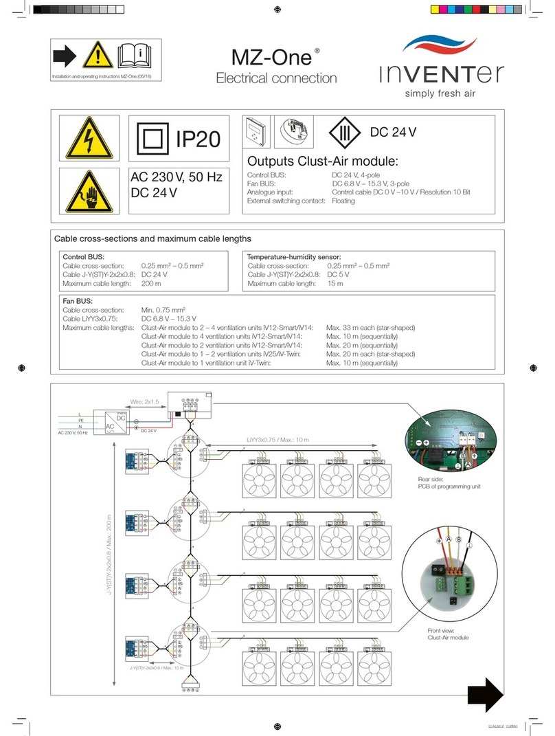
inVENTer
inVENTer MZ-One manual

Toro
Toro VISION II Series owner's manual

AWELCO
AWELCO THOR 45 user manual

