Honeywell H112 User manual
Other Honeywell Controllers manuals
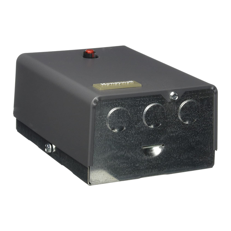
Honeywell
Honeywell R8182D Operation manual
Honeywell
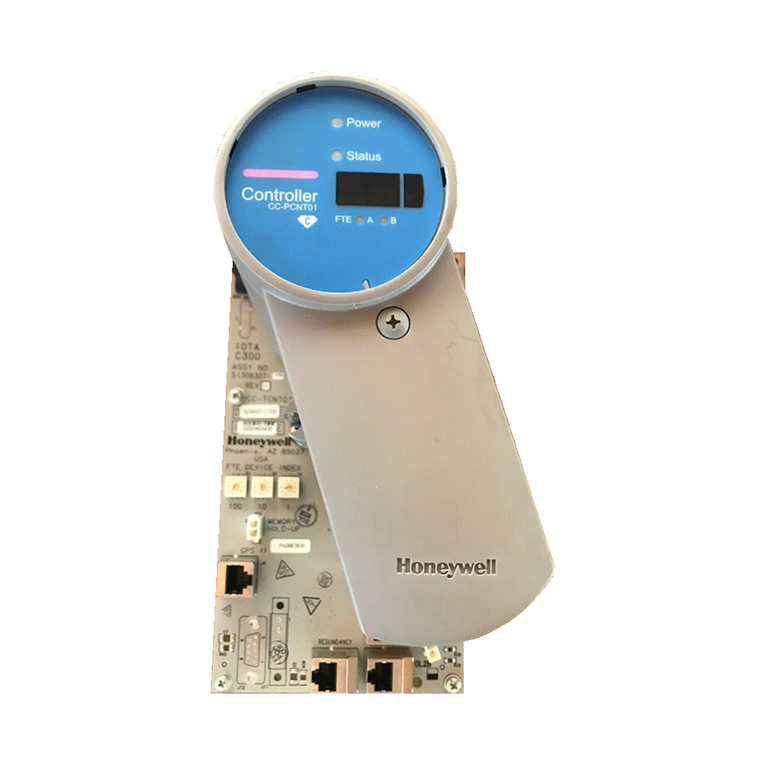
Honeywell Experion C300 User manual
Honeywell
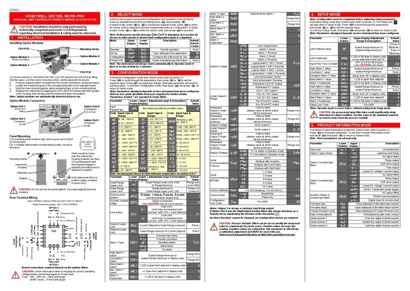
Honeywell UDC120L User manual

Honeywell
Honeywell Aquastat L8100C User manual
Honeywell
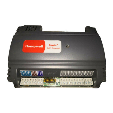
Honeywell Spyder BACnet PUB1012S User manual

Honeywell
Honeywell Touchpoint Plus Release Note

Honeywell
Honeywell UDC2000 User manual
Honeywell
Honeywell LKS 131 User manual
Honeywell
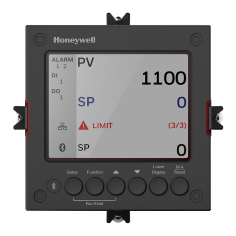
Honeywell UDC2800 User manual
Honeywell
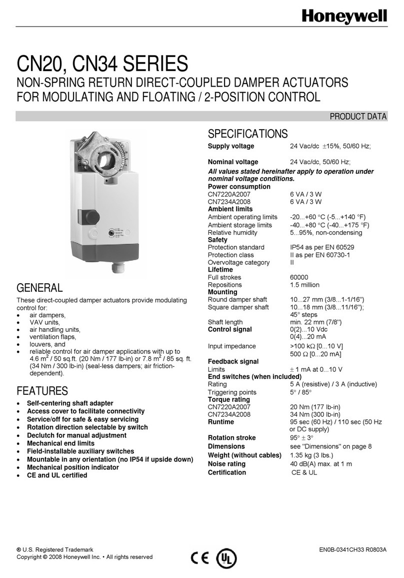
Honeywell CN34 Series Operation manual
Honeywell
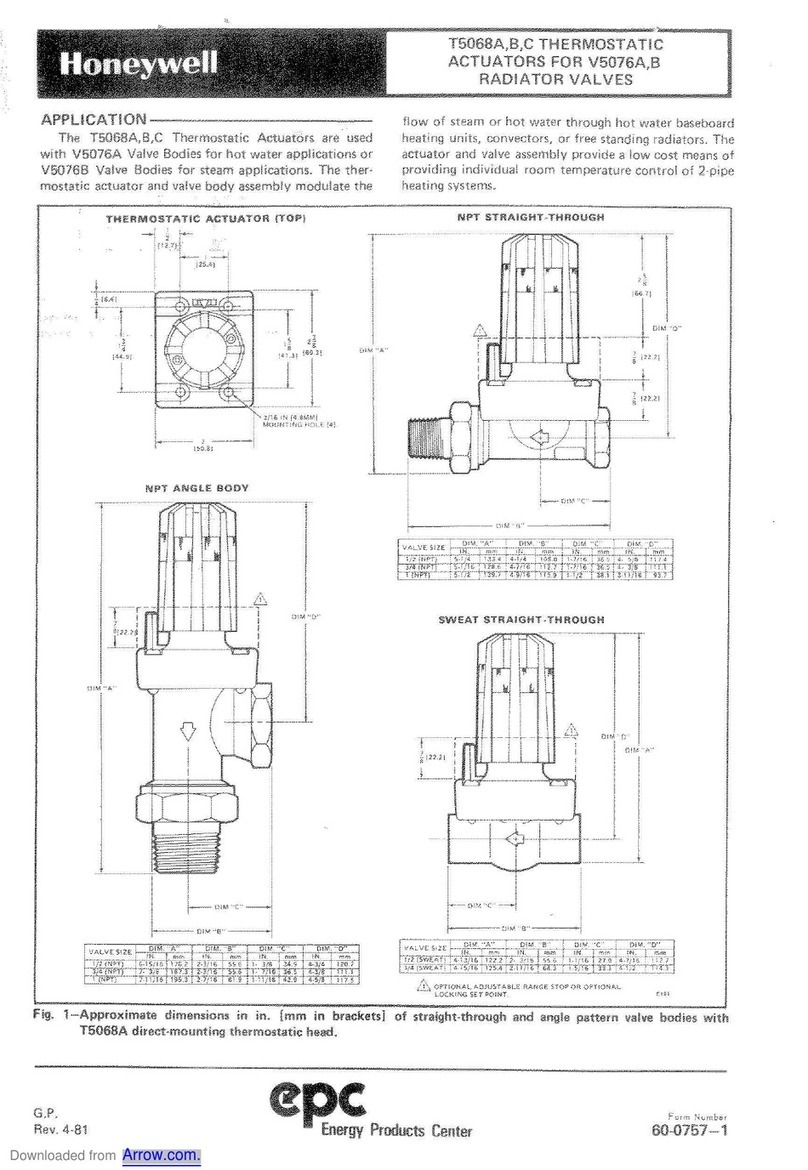
Honeywell epc T5068A User manual
Honeywell
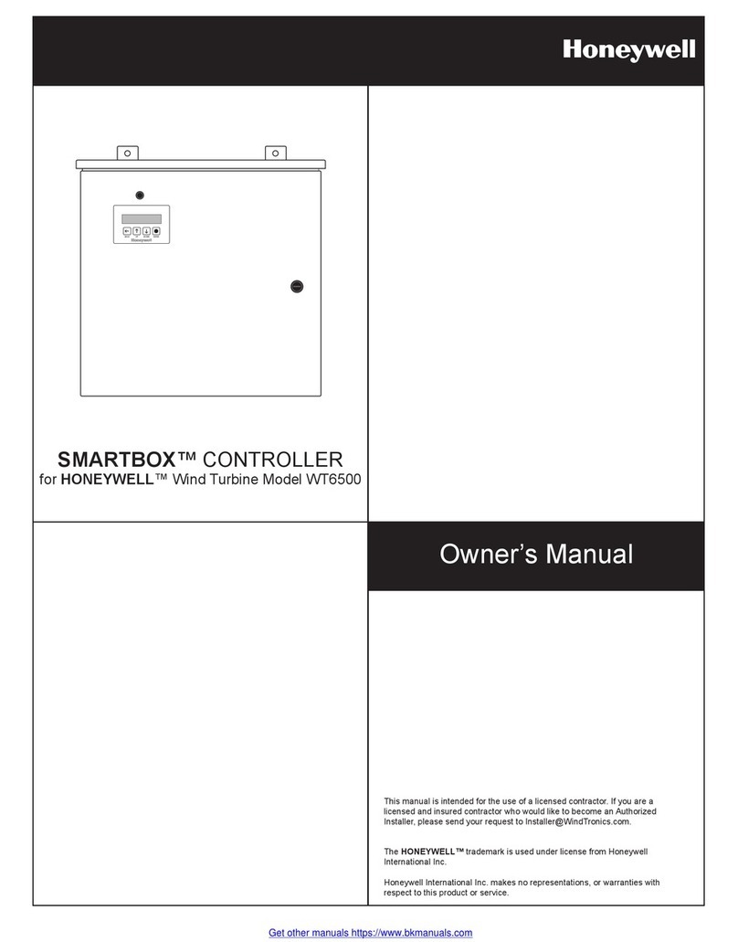
Honeywell SMARTBOX User manual

Honeywell
Honeywell ML200 Series User manual
Honeywell
Honeywell HCE80R User manual

Honeywell
Honeywell Aquastat L7224U User manual

Honeywell
Honeywell McDonald's HEMS II User manual
Honeywell
Honeywell ML7284 Operation manual
Honeywell
Honeywell MS4104F1010 User manual
Honeywell
Honeywell SLATE Series User manual
Honeywell
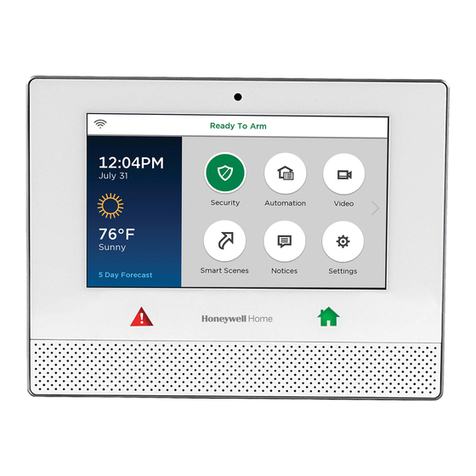
Honeywell Lyric Operating instructions
Popular Controllers manuals by other brands

Digiplex
Digiplex DGP-848 Programming guide

YASKAWA
YASKAWA SGM series user manual

Sinope
Sinope Calypso RM3500ZB installation guide

Isimet
Isimet DLA Series Style 2 Installation, Operations, Start-up and Maintenance Instructions

LSIS
LSIS sv-ip5a user manual

Airflow
Airflow Uno hab Installation and operating instructions
