manuals.online logo
Brands
  1. Home
  2. •
  3. Brands
  4. •
  5. Thermoscreens
  6. •
  7. Heater
  8. •
  9. Thermoscreens JET 6 DTAC Manual

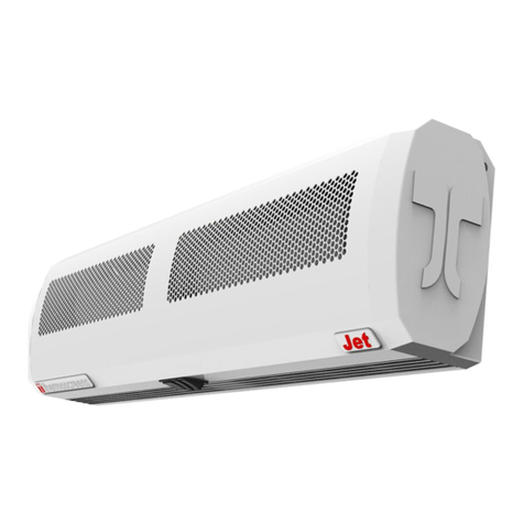
Thermoscreens JET 6 DTAC Manual

IMPORTANT INSTRUCTIONS…
Read all instructions before installing or using
this heater
… SAVE THESE INSTRUCTIONS
Important Instructions
When using electrical appliances, basic precautions should always be
followed to reduce the risk of fire, electric shock, and injury to persons,
including the following:
1. Read all instructions before installing or using this appliance.
2. This appliance is hot when in use; to avoid burns, do not let
bare skin touch hot surfaces; keep combustible materials
such as papers, clothes, bedding, etc. and curtains at least
1m from the heater.
3. Extreme caution is necessary when the unit is used by or
near children or invalids and whenever it is left operating and
unattended.
4. Do not use outdoors.
5. Do not operate any heater after it malfunctions; disconnect at
service panel. Call a competent electrical technician to
investigate.
6. Do not insert or allow foreign objects to enter the return or
discharge grilles as this may cause an electrical shock, fire or
damage to the appliance.
7. To prevent possible fire, do not block return and discharge air
grilles in any manner.
8. Do not use where flammable vapors or liquids are store.
9. Use this appliance only as described in this manual. Any
other use not recommended by the manufacturer may cause
fire, electric shock or injury to persons and property.
Model
Electrical
Input (W)
Weight
(kg)
Heat
Output
(kW)
JET 6 4965 5.5 6.0/3.0
Figure 1: Jet 6 General Assembly Drawing
CONTENTS
Remove from carton and check contents include:
 Thermoscreens Jet 6 Drive-Thru Air Curtain [DTAC] unit
 Mounting bracket [MB] c/w fixing hardware
 Cable gland
For warranty purposes please retain your receipt as proof of purchase.
INSTALLATION
The DTAC is designed for surface mounting horizontally at a discharge
height level to the sliding window header. Multiple DTACs mounted
side by side may be used for wider openings. The DTAC must be
mounted directly to the MB. The DTAC must not be located
immediately below a socket outlet. DO NOT INSTALL BOTTOM OF
HEATER LESS THAN 550mm ABOVE PLATFORM.
Figure 2: Window Header Mounting Guide
Before fitting DTAC, locate mounting hardware as necessary taking into
account the window header design and unit weight (see Table 1). Using
the MB as a template, determine an optimum location for the DTAC,
place the MB on the target location, mark position of the fixing holes to
be drilled. Using suitable fixing hardware, install the MB as required into
position. Some internal header components may have to be moved
before any drilling is conducted; it may be necessary to drill up from the
header due to design configuration of the window clearance.
Figure 3: Mounting Bracket Alignment
Align and position mounting bracket into the two slots on the rear plate
of the DTAC (refer to Figure 3). Ensure the serrated washer, at each
end of the DTAC, is positioned between the mounting bracket and the
internal hanging bracket (see Figure 4). Tilt and point DTAC into the
preferred direction and firmly tighten both fixing screws. Using a
Philips No. 2 screwdriver the fixing screws are tightened via access
hole in each end cap.
Figure 4: Cross Sectional View of Mounting Bracket
ELECTRICAL CONNECTION
All electrical wiring and connections must be carried out by a competent
qualified electrician in accordance with the latest wiring and/or local
statutory regulations.
4001360-2 1
WARNING… Risk of fire. Do not use as a
household or residential heater
JET 6 DTAC
208V ~ 60Hz 25A
Installation, Operation and
Maintenance Instructions
JET 3 2.25/1.125 kW
JET 6 4.91/2.455 kW
208V AC 60Hz
L N E
Ensure that the supply cables, circuit breakers and other electrical
installation equipment are correctly sized for the
DTAC being installed, see Table 1. For each DTAC a single phase local
isolator with a contact separation on both poles of at least 3mm must be
fitted to the supply wiring (the isolator must be fitted within an
accessible position). The DTAC should be connected to a 208V 2-pole
AC 60Hz electrical supply and must be earthed. Remove the two outer
M4 x 12mm pan head Philips screws atop the DTAC and release the
power connector plate. Fit cable gland to power connector plate. Insert
electrical supply cable via cable gland (see Figure 5) and tighten gland
around cable.
Figure 5: Electrical Connection
Connect each of the cables as follows:
 Live brown cable to terminal marked L or L1
 Neutral blue cable to terminal marked N or L2
 Earth green/yellow cable to terminal marked PE
Position the electrical supply cables as they come out of the terminal
block as shown in Figure 5. Ensure only sufficient cable is pulled
through to enable connection to terminal block and to avoid excess
cable coming into contact with any moving parts. Carefully insert all
cables through the rectangular hole in the top of the DTAC and refit the
power connector plate. Ensure mains supply cable is correctly and
sufficiently strained by the plastic cable gland.
service. Before leaving site it is important that the sliding window DTAC
installation and these instructions are “Handed-Over” to the end user or
their representative and the operation of it is fully explained and that
they understand how it operates.
THERMAL SAFETY CUT
-
OUTS
If the DTAC exceeds normal operating temperature the thermal safety
cut-outs will operate and isolate electrical supply to the heating
elements. Thermoscreens recommend only competent qualified
persons service the DTAC.
To reset the thermal safety cut-outs disconnect electrical supply to the
DTAC, determine and resolve the cause of the fault. Allow DTAC
sufficient time to cool before restoring supply. If the fault persists
arrange for a competent technician to attend site and investigate. In
order to avoid a hazard due to inadvertent resetting of the thermal cut-
out, this appliance must not be supplied through an external switching
device, such as a timer, or connected to a circuit that is regularly
switched on and off by the utility.
SERVICE
&
MAINTENANCE
Always disconnect and isolate the main electrical supply before
installing, maintaining or repairing this equipment. All
maintenance/repairs should only be carried out by a competent
electrician or Thermoscreens appointed technician. To ensure the
DTAC operates efficiently, the air inlet and outlet grilles, fan impellers,
housings and motors must be kept free of dust and debris. Regularly
vacuum and clean any build-up of dirt and debris within the DTAC
(please note that the motor is permanently lubricated and require no
additional lubrication). Once the DTAC has been cleaned check all
electrical connections within the unit ensuring terminals are tight and
that crimped connections have not become loose. If the outer casing
requires cleaning this should be carefully done using a warm soft cloth.
Do not use solvents or abrasive materials. Reconnect the electrical
supply and fully function test the DTAC to ensure correct operation.
WARRANTY
If any problems are encountered, please contact your installer or
supplier. All units are covered by a one year warranty. Subject to
availability we undertake to repair or exchange this product.
Care has been taken in compiling these instructions to ensure they are
correct, although Thermoscreens disclaims all liability for damage
resulting from any inaccuracies and/or deficiencies in this
documentation. Thermoscreens retain the right to change the
specifications stated in these instructions.
Conforms to: CAN CSA-C22.2 no.46-13 & UL 2021(Ed.3): 2013
Figure 6: Jet 6 Wiring Diagram
O
PERATION
Control of the DTAC is achieved by using the three integral switches
mounted adjacent to the discharge grille.
Switch Action
I Fan on
I + Middle Fan + half heat
I + Middle + End Fan + full heat
The DTAC panels are coated in an easy to peel protective film. Please
ensure all the protective film is removed before the DTAC is put into
2
Thermoscreens Canada 11 King St. Unit #3
Barrie, Ontario Canada L4N 6B5
Toll Free: 877 445 3739 Tel: 705 797 0007 Fax: 705 797 0013
e-mail: salescanada@thermoscreens.com www.thermoscreens.com
Other Thermoscreens Heater manuals

Thermoscreens Designer Series Guide

Thermoscreens

Thermoscreens Designer Series Guide

Thermoscreens CS 1000 Manual

Thermoscreens

Thermoscreens CS 1000 Manual

Thermoscreens HX Series Manual

Thermoscreens

Thermoscreens HX Series Manual

Thermoscreens PHV1000A User manual

Thermoscreens

Thermoscreens PHV1000A User manual

Thermoscreens HX CS 1000 Series User manual

Thermoscreens

Thermoscreens HX CS 1000 Series User manual

Thermoscreens Compact 2 Series Manual

Thermoscreens

Thermoscreens Compact 2 Series Manual

Thermoscreens HX Series Guide

Thermoscreens

Thermoscreens HX Series Guide

Thermoscreens HX1000AR Manual

Thermoscreens

Thermoscreens HX1000AR Manual

Thermoscreens T Series Installation guide

Thermoscreens

Thermoscreens T Series Installation guide

Thermoscreens C1000R Guide

Thermoscreens

Thermoscreens C1000R Guide

Thermoscreens JET 3 Manual

Thermoscreens

Thermoscreens JET 3 Manual

Thermoscreens Designer PHV Series Manual

Thermoscreens

Thermoscreens Designer PHV Series Manual

Thermoscreens TX36AFAL006D Owner's manual

Thermoscreens

Thermoscreens TX36AFAL006D Owner's manual

Thermoscreens T600 Series User manual

Thermoscreens

Thermoscreens T600 Series User manual

Thermoscreens C1000R Guide

Thermoscreens

Thermoscreens C1000R Guide

Thermoscreens HX Series Manual

Thermoscreens

Thermoscreens HX Series Manual

Thermoscreens Jet 3 Manual

Thermoscreens

Thermoscreens Jet 3 Manual

Thermoscreens VRF PHV1000 DXE HO Guide

Thermoscreens

Thermoscreens VRF PHV1000 DXE HO Guide

Thermoscreens PHV V NT series Guide

Thermoscreens

Thermoscreens PHV V NT series Guide

Popular Heater manuals by other brands

Envi LE5012P owner's manual

Envi

Envi LE5012P owner's manual

Desa ReDDY HeaTeR RV125EDI owner's manual

Desa

Desa ReDDY HeaTeR RV125EDI owner's manual

Master BV125EDI owner's manual

Master

Master BV125EDI owner's manual

DutchWest 2478 Homeowner's installation and operating manual

DutchWest

DutchWest 2478 Homeowner's installation and operating manual

EUROM 363913 instruction manual

EUROM

EUROM 363913 instruction manual

Dimplex FrostWatcher FW600 instructions

Dimplex

Dimplex FrostWatcher FW600 instructions

Dometic TwinBoost4000 Installation and service manual

Dometic

Dometic TwinBoost4000 Installation and service manual

Claudgen HE7010 Additional Installation, Operation and Maintenance Instructions

Claudgen

Claudgen HE7010 Additional Installation, Operation and Maintenance Instructions

Protemp PT-200V-LPC-A User's manual & operating instructions

Protemp

Protemp PT-200V-LPC-A User's manual & operating instructions

Toolland FT 90 instruction manual

Toolland

Toolland FT 90 instruction manual

DeWalt DXH2000TS instruction manual

DeWalt

DeWalt DXH2000TS instruction manual

Archgard 27-DVIM22N-2 Installation, operation and maintenance manual

Archgard

Archgard 27-DVIM22N-2 Installation, operation and maintenance manual

RADtec T15FS instruction manual

RADtec

RADtec T15FS instruction manual

THERMOBILE AGA 111 user manual

THERMOBILE

THERMOBILE AGA 111 user manual

Reznor EURO-C 4000 RJL Instruction document

Reznor

Reznor EURO-C 4000 RJL Instruction document

Mi-T-M MH-0060-LM10 Operator's manual

Mi-T-M

Mi-T-M MH-0060-LM10 Operator's manual

Steba KH5 Instructions for use

Steba

Steba KH5 Instructions for use

Living & Co PTC-1819M user manual

Living & Co

Living & Co PTC-1819M user manual

manuals.online logo
manuals.online logoBrands
  • About & Mission
  • Contact us
  • Privacy Policy
  • Terms and Conditions

Copyright 2025 Manuals.Online. All Rights Reserved.