manuals.online logo
Brands
  1. Home
  2. •
  3. Brands
  4. •
  5. Thermoscreens
  6. •
  7. Heater
  8. •
  9. Thermoscreens JET 3 Manual

Thermoscreens JET 3 Manual

JET 3, 4.5 & 6 Over Door Heaters.
4001260-4 IO 1
PLEASE READ THESE INSTRUCTIONS CAREFULLY BEFORE
INSTALLATION AND RETAIN FOR FUTURE REFERENCE
Figure 1: Jet Range General Assembly Drawing
Model Electrical
Input (W) Weight
(kg)
Heat
Output
(kW)
JET 3 3030 4.5 3.0/1.5
JET 4.5 4540 5.5 4.5/2.25
JET 6 6055 5.5 6.0/3.0
Table 1: Jet Over Door Heater Range
CONTENTS
Remove from carton and check contents include:
•Thermoscreens Jet heater unit
•Mounting bracket
•Cable gland (supplied loose)
For warranty purposes please retain your receipt as proof of
purchase.
INSTALLATION
The Jet heater is designed for surface mounting horizontally
above a door opening at a height of 1.8m minimum to 2.3m
maximum (from floor level to the underside of the appliance).
Multiple Jet heaters mounted side by side may be used for
wider doorways. The heater must be mounted internally
within a building and can be either wall or ceiling mounted.
Figure 2: Wall or Ceiling Mounting Options
Before fitting heater obtain suitable screws and wall plugs,
taking into account wall or ceiling type and unit weight (see
Table 1). The heater must not be located immediately below
a socket outlet. Do not cover or obstruct the air inlet or outlet
grilles as this can cause overheating and may cause a risk of
fire. Do not install heater in environments containing
flammable or explosive material.
Using the mounting bracket as a template determine optimum
location for the heater, place bracket on the wall or ceiling and
mark position of the two fixing holes (refer to ‘B’ in Figure 1).
Drill wall or ceiling accordingly and securely fix mounting
bracket into position.
Figure 3: Mounting Bracket Alignment
Align and position mounting bracket into the two slots on the
rear plate of the heater (refer to Figure 3).
Ensure the serrated washer, at each end of the heater, is
positioned between the mounting bracket and the internal
hanging bracket (see Figure 4). Tilt and point heater into the
preferred direction and firmly tighten both fixing screws.
Using a Pozi No. 2 screwdriver the fixing screws are tightened
via access hole in each end cap.
Figure 4: Cross Sectional View of Mounting Bracket
ELECTRICAL CONNECTION
All electrical wiring and connections must be carried out by a
competent qualified electrician in accordance with the latest
edition of the IEE wiring regulations and/or local statutory
regulations.
Installation, Operation and Maintenance Instructions
2
Ensure that the supply cables, circuit breakers and other
electrical installation equipment are correctly sized for the
heater being installed, see Table 1. For each heater a single
phase local isolator with a contact separation on both poles of
at least 3mm must be fitted to the supply wiring (the isolator
must be fitted within an accessible position). The heater
should be connected to a 230V AC 50Hz electrical supply and
must be earthed. Use 3-core round flexible mains cable type
3183Y for the final connection to the heater from the local
isolator.
JET 3 15A 1.5mm2
JET 4.5 20A 2.5mm2
JET 6 32A 4.0mm2
Remove two M4 x 12mm pan head Pozi screws at top of the
heater and release the power connector plate. Fit cable gland
to power connector plate. Insert electrical supply cable via
cable gland (see Figure 5) and tighten gland around cable.
Figure 5: Electrical Connection
Connect each of the cables as follows:-
•Live brown cable to terminal marked L
•Neutral blue cable to terminal marked N
•Earth green/yellow cable to terminal marked
Position the electrical supply cables as they come out of the
terminal block as shown in Figure 5. Ensure only sufficient
cable is pulled through to enable connection to terminal block
and to avoid excess cable coming into contact with any
moving parts. Carefully insert all cables through the
rectangular hole in the top of the heater and refit the power
connector plate. Ensure mains supply cable is correctly and
sufficiently strained by the plastic cable gland.
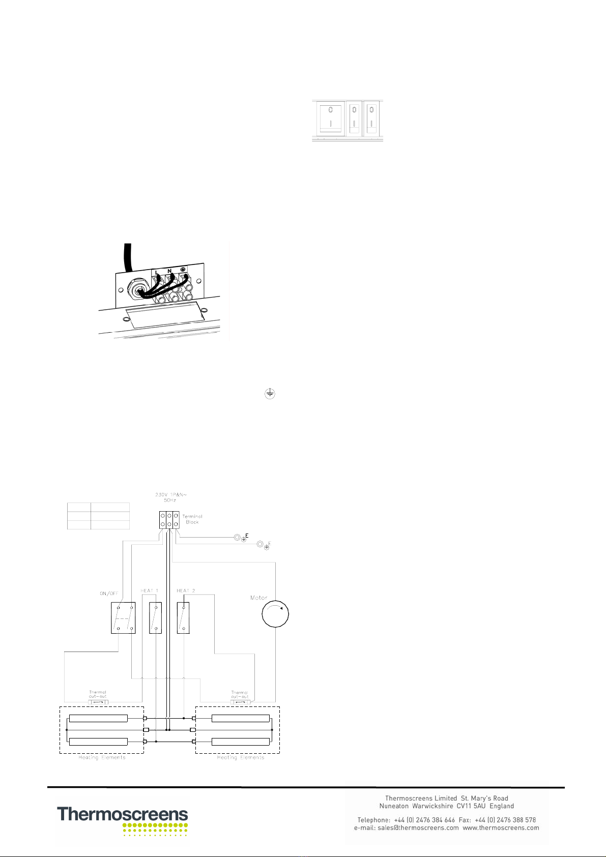
LNE
JET 3 1.5/3.0kW
JET 4.5 2.25/4.5kW
JET 6 3.0/6.0kW
Figure 6: Jet Range Layout Diagram
OPERATION
Control of the heater is achieved by using the three integral
switches mounted adjacent to the discharge grille.
Switch Action
I Fan on
I + I (Middle) Fan + half heat
I + I (Middle) + I (End) Fan + full heat
The heater panels are coated in an easy to peel protective
film. Please ensure all the protective film is removed before
the air curtain is put into service.
Before leaving site it is important that the over door heater
installation and these instructions are “Handed-Over” to the
end user or their representative and the operation of it is fully
explained and that they understand how it operates.
Note: This appliance is not intended for use by persons
(including children) with reduced physical, sensory or mental
capabilities, or lack of experience and knowledge, unless they
have been given supervision or instruction concerning use of
the appliance by a person responsible for their safety.
Children should be supervised to ensure that they do not play
with the appliance.
THERMAL SAFETY CUT-OUTS
If the heater exceeds normal operating temperature the
thermal safety cut-outs will operate and isolate electrical
supply to the heating elements. Thermoscreens recommend
only competent qualified persons service the heater.
To reset the thermal safety cut-outs disconnect electrical
supply to the heater, determine and resolve the cause of the
fault. Allow heater sufficient time to cool before restoring
supply. If the fault persists arrange for a competent engineer
to attend site and investigate.
In order to avoid a hazard due to inadvertent resetting of the
thermal cut-out, this appliance must not be supplied through
an external switching device, such as a timer, or connected to
a circuit that is regularly switched on and off by the utility.
SERVICE &MAINTENANCE
Always disconnect and isolate the mains electricity supply
before installing, maintaining or repairing this equipment. All
maintenance/repairs should only be carried out by a
competent electrician or Thermoscreens appointed
technician. To ensure the heater operates efficiently the air
inlet and outlet grilles, fan impellers, housings and motors
must be kept free of dust and debris. Regularly vacuum and
clean any build-up of dirt and debris within the heater (please
note that the motor is permanently lubricated and require no
additional lubrication). Once the heater has been cleaned
check all electrical connections within the unit ensuring
terminals are tight and that crimped connections have not
become loose. If the outer casing requires cleaning this
should be carefully done using a warm soft cloth. Do not use
solvents or abrasive materials.
Reconnect the electrical supply and fully function test the
heater to ensure correct operation.
WARRANTY
If any problems are encountered, please contact your installer
or supplier. Failing this please contact the Thermoscreens
warranty department. All units are covered by a one year
warranty. Subject to availability we undertake to repair or
exchange this product.
Care has been taken in compiling these instructions to ensure
they are correct, although Thermoscreens disclaims all liability
for damage resulting from any inaccuracies and/or
deficiencies in this documentation. Thermoscreens retain the
right to change the specifications stated in these instructions.

This manual suits for next models

2

Other Thermoscreens Heater manuals

Thermoscreens HX CS 1000 Series User manual

Thermoscreens

Thermoscreens HX CS 1000 Series User manual

Thermoscreens Designer Series Guide

Thermoscreens

Thermoscreens Designer Series Guide

Thermoscreens T Series Installation guide

Thermoscreens

Thermoscreens T Series Installation guide

Thermoscreens PHV1000A User manual

Thermoscreens

Thermoscreens PHV1000A User manual

Thermoscreens Designer PHV Series Manual

Thermoscreens

Thermoscreens Designer PHV Series Manual

Thermoscreens HX Series Manual

Thermoscreens

Thermoscreens HX Series Manual

Thermoscreens HX Series Manual

Thermoscreens

Thermoscreens HX Series Manual

Thermoscreens HX Series Guide

Thermoscreens

Thermoscreens HX Series Guide

Thermoscreens HX1000AR Manual

Thermoscreens

Thermoscreens HX1000AR Manual

Thermoscreens CS 1000 Manual

Thermoscreens

Thermoscreens CS 1000 Manual

Thermoscreens C1000R Guide

Thermoscreens

Thermoscreens C1000R Guide

Thermoscreens C1000R Guide

Thermoscreens

Thermoscreens C1000R Guide

Thermoscreens VRF PHV1000 DXE HO Guide

Thermoscreens

Thermoscreens VRF PHV1000 DXE HO Guide

Thermoscreens T600 Series User manual

Thermoscreens

Thermoscreens T600 Series User manual

Thermoscreens Compact 2 Series Manual

Thermoscreens

Thermoscreens Compact 2 Series Manual

Thermoscreens PHV V NT series Guide

Thermoscreens

Thermoscreens PHV V NT series Guide

Thermoscreens JET 6 DTAC Manual

Thermoscreens

Thermoscreens JET 6 DTAC Manual

Thermoscreens TX36AFAL006D Owner's manual

Thermoscreens

Thermoscreens TX36AFAL006D Owner's manual

Thermoscreens Jet 3 Manual

Thermoscreens

Thermoscreens Jet 3 Manual

Popular Heater manuals by other brands

BELLAGIO H1C009WSNB owner's manual

BELLAGIO

BELLAGIO H1C009WSNB owner's manual

Dimplex CASSADO CSO20 manual

Dimplex

Dimplex CASSADO CSO20 manual

Pentair FreezGard CCH-1C installation instructions

Pentair

Pentair FreezGard CCH-1C installation instructions

BIEMMEDUE GAN instruction manual

BIEMMEDUE

BIEMMEDUE GAN instruction manual

Mi-Heat 1317 instruction manual

Mi-Heat

Mi-Heat 1317 instruction manual

Supra Dalbeo Presence 1022 Installation and operating instructions

Supra

Supra Dalbeo Presence 1022 Installation and operating instructions

TERMOFOL TF-1000WIFI Installation & operation instructions

TERMOFOL

TERMOFOL TF-1000WIFI Installation & operation instructions

Flagro THC-175DF manual

Flagro

Flagro THC-175DF manual

Rinnai RHFE-309FT Operation and installation manual

Rinnai

Rinnai RHFE-309FT Operation and installation manual

Master CF 75 User and Maintenance Book

Master

Master CF 75 User and Maintenance Book

IRSAP 1009M0622 manual

IRSAP

IRSAP 1009M0622 manual

Greenlee 851 instruction manual

Greenlee

Greenlee 851 instruction manual

TigerKing SF-2 manual

TigerKing

TigerKing SF-2 manual

Miller ArcReach owner's manual

Miller

Miller ArcReach owner's manual

DeLonghi DCH5531 Instructions for use

DeLonghi

DeLonghi DCH5531 Instructions for use

NOBOCOOL N4EU Operational instructions

NOBOCOOL

NOBOCOOL N4EU Operational instructions

HeatStar HSU50 Operating instructions and owner's manual

HeatStar

HeatStar HSU50 Operating instructions and owner's manual

Arlec Simone user manual

Arlec

Arlec Simone user manual

manuals.online logo
manuals.online logoBrands
  • About & Mission
  • Contact us
  • Privacy Policy
  • Terms and Conditions

Copyright 2025 Manuals.Online. All Rights Reserved.