manuals.online logo
Brands
  1. Home
  2. •
  3. Brands
  4. •
  5. Thermoscreens
  6. •
  7. Heater
  8. •
  9. Thermoscreens T600 Series User manual

Thermoscreens T600 Series User manual

Page 1 of 5
Engineering change number: 03/00092 Dwg No. 4007100-1
Issued: 16/01/04
FOR INDOOR USE ONLY
INSTALLATION AND OPERATING INSTRUCTIONS
PLEASE READ INSTRUCTIONS CAREFULLY BEFORE ATTEMPTING INSTALLATION!
T600/T800 Series.
Overdoor Heaters
Engineering change number: 03/00092 Dwg No. 4007100-1
Issued: 16/01/04
UN-PACKING YOUR RECESSED AIR-CURTAIN
The following items are supplied.
•RECESSED AIR-CURTAIN
•REMOTE SWITCH UNIT
C/W 3.0m lead
(The remote switch unit is
located inside of the air
curtain).
•RECESSED GRILLE
If anything is missing or damaged please contact your place of purchase immediately.
For your records
Date of purchase:
Place of purchase:
Serial Number:
For warranty purposes, proof of purchase is necessary, so please keep a copy of your
invoice.
(Please note that all documentation remains the property of the building and should be stored
accordingly)
Page 2 of 5
Page 3 of 5
Engineering change number: 03/00092 Dwg No. 4007100-1
Issued: 16/01/04
INSTALLATION OF YOUR T600ER & T800ER UNIT
•Location
The T600ER & T800ER are designed for recessing/mounting within a ceiling void or bulkhead
(minimum height of 1.8 – to maximum height of 2.3m.
When mounting ensure that the air discharge is situated as close to the door as possible, the
T600ER & T800ER are designed to fit directly into a ceiling tile grid formation (T600ER –
595mm (l) to suit 600mm grid & the T800ER 895mm (l) to suit 900mm grid) if the grid does not
align with the door then the grid will need modifying.
Note: an air gap of 50mm is required around the external casing.
•Ceiling suspension
Each unit is provided with 4 x M6 inserts (two either end) to allow the unit to be suspended via
threaded rods or wire tie (see figure 1 below).
Please note when fixing using threaded rods or wire ties (not supplied) that a suitable structure
is used ensuring that it can maintain the unit weight adequately, for unit weights see table 1).
Ensure that locking nuts are fitted (not supplied) to stop the threaded bar/wire ties rotating and
coming away from the casing.
For dimensions of fixing centres please see figure 1 below.
Figure 1
Page 4 of 5
Engineering change number: 03/00092 Dwg No. 4007100-1
Issued: 16/01/04
•Electrical connections
WARNING!
Units should only be wired by a competent electrician in accordance with the latest
edition of the IEE wiring regulations and/or local statutory regulations.
Ensure that the supply cables and circuit breakers are sufficient for the air-curtain(s) being
installed (for electrical loading see table 1 below).
A single-phase isolator rated appropriately must be fitted to the supply wiring with a contact
separation of at least 3mm.
Table 1
Air-curtain Supply Heat output Input (A) Weight
T600ER 230V 50Hz 1P&N~ 1.5/3.0kW 13.5A 7.5kg
T800ER 230V 50Hz 1P&N~ 3.0/4.5kW 20.0A 8.5kg
To gain access to the electrical connections the recessed grille must be removed (the grille is
secured to the frame of the air curtain via 4 cross head screws) to remove the grille from the unit
remove the screws and lift the grille clear, access can be gained to the mains supply & remote
switch terminals inside the air curtain (located at the left hand end of the unit).
Four sets of cable entry holes are provided (20mm knock outs) within the casing, two via the
end cap for side entry & two via the back case for top entry. Once the appropriate cable entry
glands have been fitted (to be supplied by installer in accordance to the latest edition of IEE
regulations or local regulations in use) proceed to connect the supply/remote switch to the unit
as per the attached wiring diagram, when fitting the remote switch ensure that it is located in a
suitable place for easy access.
•Operation
All units are supplied with a remote switch that gives the following functions; On/off & two heat
settings (for heat output see above table).
For thermostatic control a room thermostat maybe connected in series with terminal 4 to give
control over the second stage of heat.
•Fault conditions
In the event of a fault the thermal cut out or the internal fuse may operate. The thermal cut out is
located at the left hand end of the unit, the internal fuse is located within the terminals mounted
at the left hand end.
In the case of a fault condition do not attempt to reset the thermal cut out or replace the fuse,
arrange for a Thermoscreens appointed engineer or certified electrician to attend the unit to
investigate the reason why the thermal cut outs/fuse have operated, once the cause has been
determined and rectified, proceed to reset/replace the thermal cut out/fuse and function test the
unit.
Page 5 of 5
Engineering change number: 03/00092 Dwg No. 4007100-1
Issued: 16/01/04
•Air flow
When installing the
air curtain ensure
that the air stream
is as close to the
door opening as
possible to give
optimum
performance (see
figure inset).
•Service & Maintenance
Always disconnect/isolate the mains electricity supply before maintaining or repairing
this equipment (Note: All maintenance/repairs should be carried out by a competent
electrician or Thermoscreens service agent)
To ensure the air curtain operates at full efficiency the inlet/outlet grilles, impellers, housings
and motors must be kept free of dust and debris. Build up of dust on the impellers can cause
vibration, noise and excessive wear on the impeller/motor bearings.
Frequency of cleaning will depend on the environment, but we would recommend that the unit
be cleaned a minimum of every 3 months (failure to adequately maintain the unit and provide a
suitable cleaning schedule will result in performance degradation and reduce the life expectancy
of the air-curtain).
Once the mains supply is isolated, remove the grille (this is done by removing the four cross
head screws and lifting the grille clear) access can now be gained to the air curtain.
Vacuum and clean the built up dirt and debris within the air-curtain (please note that the
motor(s) and bearings are permanently sealed and require no additional lubrication). Re-install
the grille, reconnect the power and fully function test the air-curtain to ensure correct operation.
•Warranty
If any problems are encountered, please contact your installer/supplier failing this please
contact the Thermoscreens warranty department.
Thermoscreens Ltd
St. Mary’s Road
Nuneaton
Warwickshire
England
CV11 5AU
Tel + 44 (0) 24 7638 4646
Fax + 44 (0) 24 7638 8578
Email: [email protected]
www.thermoscreens.com

This manual suits for next models

1

Other Thermoscreens Heater manuals

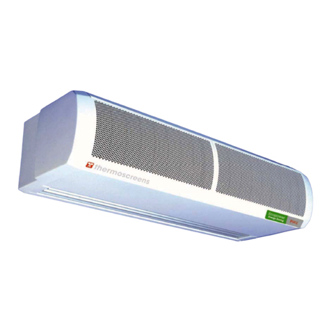
Thermoscreens PHV1000A User manual

Thermoscreens

Thermoscreens PHV1000A User manual
Thermoscreens CS 1000 Manual

Thermoscreens

Thermoscreens CS 1000 Manual
Thermoscreens Compact 2 Series Manual

Thermoscreens

Thermoscreens Compact 2 Series Manual
Thermoscreens Designer PHV Series Manual
Thermoscreens

Thermoscreens Designer PHV Series Manual

Thermoscreens PHV V NT series Guide

Thermoscreens

Thermoscreens PHV V NT series Guide
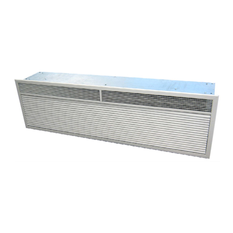
Thermoscreens HX1000AR Manual

Thermoscreens

Thermoscreens HX1000AR Manual
Thermoscreens HX Series Manual

Thermoscreens

Thermoscreens HX Series Manual

Thermoscreens HX CS 1000 Series User manual
Thermoscreens

Thermoscreens HX CS 1000 Series User manual

Thermoscreens HX Series Manual

Thermoscreens

Thermoscreens HX Series Manual
Thermoscreens Jet 3 Manual

Thermoscreens

Thermoscreens Jet 3 Manual

Thermoscreens JET 6 DTAC Manual

Thermoscreens

Thermoscreens JET 6 DTAC Manual
Thermoscreens T Series Installation guide
Thermoscreens

Thermoscreens T Series Installation guide

Thermoscreens Designer Series Guide

Thermoscreens

Thermoscreens Designer Series Guide

Thermoscreens C1000R Guide

Thermoscreens

Thermoscreens C1000R Guide
Thermoscreens JET 3 Manual

Thermoscreens

Thermoscreens JET 3 Manual

Thermoscreens C1000R Guide

Thermoscreens

Thermoscreens C1000R Guide

Thermoscreens VRF PHV1000 DXE HO Guide

Thermoscreens

Thermoscreens VRF PHV1000 DXE HO Guide

Thermoscreens HX Series Guide

Thermoscreens

Thermoscreens HX Series Guide
Thermoscreens TX36AFAL006D Owner's manual

Thermoscreens

Thermoscreens TX36AFAL006D Owner's manual

Popular Heater manuals by other brands
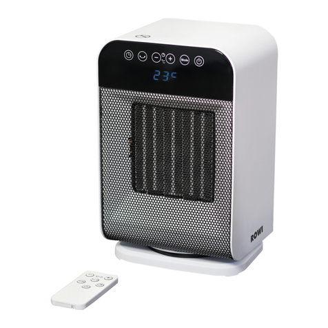
Rowi HKH 2000/2/1 ODT Premium Original instruction manual
Rowi

Rowi HKH 2000/2/1 ODT Premium Original instruction manual

HeatStar HSU100NGPALP Operating instructions and owner's manual

HeatStar

HeatStar HSU100NGPALP Operating instructions and owner's manual

ELECTROTEK ET-QH01 instruction manual

ELECTROTEK

ELECTROTEK ET-QH01 instruction manual

Prem-I-Air EH1526 manual

Prem-I-Air

Prem-I-Air EH1526 manual

Outsunny 842-179 Assembly instructions
Outsunny

Outsunny 842-179 Assembly instructions

Temp-Heat THP-750 Installation and service manual

Temp-Heat

Temp-Heat THP-750 Installation and service manual

Stanley ST-40-GFA-E User's manual and operating instructions
Stanley

Stanley ST-40-GFA-E User's manual and operating instructions

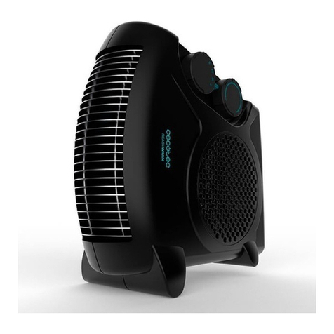
cecotec Ready Warm 9700 Dual Force instruction manual

cecotec

cecotec Ready Warm 9700 Dual Force instruction manual

GSI Group 2000 Series Installation and operating instructions

GSI Group

GSI Group 2000 Series Installation and operating instructions

Lasco CC13650 operating manual

Lasco

Lasco CC13650 operating manual

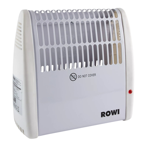
Rowi HFW 400/1/1 operating instructions

Rowi

Rowi HFW 400/1/1 operating instructions

Costway EP23750 user manual

Costway

Costway EP23750 user manual

Vitek VT-1703 Manual instruction

Vitek

Vitek VT-1703 Manual instruction

Raider RD-EFH08 user manual

Raider

Raider RD-EFH08 user manual

IVT GFH-10ATD instruction manual

IVT

IVT GFH-10ATD instruction manual

Tecnogas Tecnobreeze 14261 manual

Tecnogas

Tecnogas Tecnobreeze 14261 manual

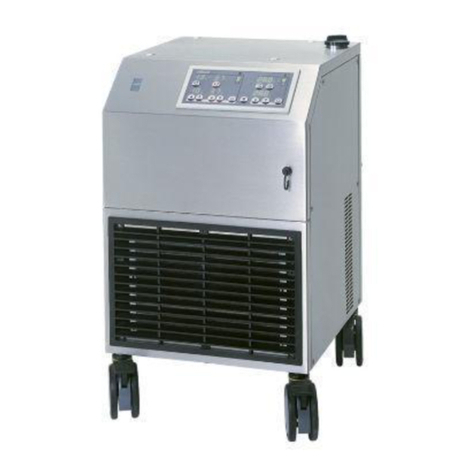
sorin 3T operating instructions

sorin

sorin 3T operating instructions

MEI HK 3011 instruction manual

MEI

MEI HK 3011 instruction manual

manuals.online logo
manuals.online logoBrands
  • About & Mission
  • Contact us
  • Privacy Policy
  • Terms and Conditions

Copyright 2025 Manuals.Online. All Rights Reserved.