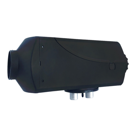
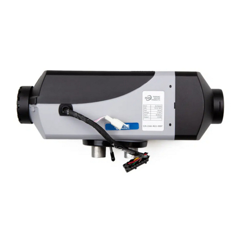
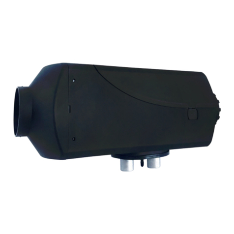
PHP PH51W Parts list manual

®
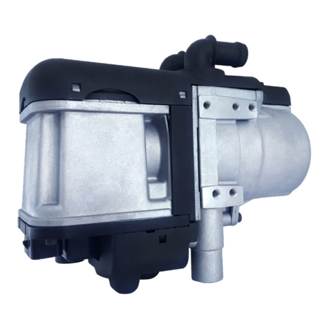
PH51W COOLANT HEATER
Technical Description
Installation Instructions
Operating Instructions
Troubleshooting and Parts


3
Table of Contents
Introduction 4
Heater Warnings 5
Specications 6
Heater Components and Operating Concept 7
Heater Kit List 8
Heater Mounting 10
Exhaust & Combustion Air Intake Connections 11
Heater Plumbing 13
Fuel System 15
Electrical Connections 18
Operating Switch 20
Heater Operation 29
Maintenance, Troubleshooting & Parts 31
Heater Components 33

4
Introduction
Thank you for purchasing our PH51W heater kit.
The PH51W heater is designed to preheat your engine by using on-board diesel fuel and
battery systems. Operation is simple and the heater provides a safe and reliable alternative to
cold engine starting or need for electrical plug ins.
Please take a moment to familiarize yourself with this manual, safety warnings and heater
requirements before installing or operating your heater.

5
Heater Warnings
Special Notes
Note: Highlight areas requiring special attention or clarication.
Warning
Caution
Indicates that personal injury or damage to equipment may occur unless specic guidelines
are followed.
Indicates that serious or fatal injury may result if specic guidelines are not followed.
Caution - Operational Considerations
• The installation of this kit requires trained decision-
making concerning locating and integrating components,
tying components together, rerouting, or relocating OEM
components, etc.
• It is impossible to describe all of the safety and operational
considerations in the installation instructions. Therefore,
the technician must exercise professional judgment to
achieve a safe and quality installation.
• Read and understand this manual before attempting to
install the heater.
• Failure to follow all these instructions could cause serious
or fatal injury.
• Ensure a proper mixture of water and antifreeze to prevent
coolant from Freezing.
• Ensure that the coolant ow can never be blocked while
heater is in operation.
• Blocking coolant ow can result in extreme pressure,
bursting hoses and release of scalding coolant.
This heater is not designed for use with straight bio-diesel
(Blends of bio-diesel up to 10% are acceptable)
Operating outside of these conditions may plug the heater
with soot and result in combustion failure.
This heater is not designed to operate continuously at
altitudes above 1500 meters (4920’).
Operating in these conditions may plug the heater with soot
and result in combustion failure.
• Heater must be turned o while re-fueling.
• Do not install heater in enclosed areas where combustible
fumes may be present.
• Exhaust pipe must maintain a minimum a distance of
50mm (2”) from any ammable or heat sensitive material.
• Ensure there are no leaks in the fuel system.
• Ensure that exhaust fumes cannot enter passenger
compartments.
Warning - Installation Hazards
Warning - Burn Hazards
Bio-Diesel
High Altitudes
Warning - Explosion Hazards
Warning - Fire Hazards
Warning - Asphyxiation Hazards

6
Specications
Principal Dimensions
1
Technical data and specications
Heat ow control
♦ Please note:
♦ Heater Dimensions
Water outlet
Water inlet
Fuel
supply
line
Combustion air Exhaust
Performance Specifications
Heating Medium Water / Ethylene Glycol Mixture
Fuel Diesel
Heating Output High – 4.2 KW (14,400 BTU)
Low – 2.2 KW (7,500 BTU)
Fuel Consumption High – 0.51 L/hr (0.13US Gal/hr)
Low – 0.25 L/hr (0.06 US Gal/hr)
Rated Voltage 12 VDC or 24 VDC
Power Consumption
Watts
High – 53W
Low – 27 W
Startup – 120 W
Operating Voltage Range:
Minimum Voltage
10.2 V or 21V
Under-voltage protection will shutdown the units
when the voltage drops to this value
Operating Voltage Range:
Maximum Voltage
16 V or 32V
Over-voltage protection will shutdown the units when
the voltage reaches this value
Allowable Operating Pressure 1 bar (15 PSI)
Water Capacity (Heater) 0.175 L (0.046 US Gal)
Water Through Capacity 850-1000 L/h (225-265 US Gal/h)
At 10 Kpa Operational Pressure
Minimum Water Through-put 240 L/h (63.50 US Gal/h)
Allowable Ambient Temperature -40°C to 80°C
-40°F to 176°F
Dry Weight 3.1 kg (6.8 lbs)
Above Specifications (± 10%)

7
Main Components and Operating Concept
Main parts of PH51W water heaters
♦
1
2
3
4
1. Heat Exchanger 4. Glow Pin
2. Integrated Coolant Pump Assembly 5. Fuel Metering Pump
3. Combustion Air Blower
Basic Operation of Heater
• Fuel is delivered to the heater via the heater’s fuel pump.
• Combustion air is delivered to the heater via the heaters 12v combustion air blower.
• Fuel is atomized and the fuel / air mixture is ignited using a glow pin.
• The ame is contained in a ame tube and exhaust gases expelled.
• The heater’s coolant pump takes cold coolant from the engine, circulates it through the heater’s water
jacket, then it pumps hot coolant back to the engine.
5

8
Heater Kit List
Part Number QTY Description
P51W-T801 1 Heater
P65D-X302 1 Standard Operating Switch
P65D-X301 Operating Switch-7 day Timer (option)
P51W-X703 1 Heater Mounting Bracket
P65W-X303 1 Wiring Harness
5M (16’) Power Harness, 20A Fuse
2.5M (9’) Fuel Pump Harness
5M (16’) Switch Harness, 5A Fuse
2.5M (8’) Remote Sensor Harness
U65D-X508 1 Flexible Stainless-Steel Exhaust,
1M x 24mm with End Cap
U51W-X501 1 Combustion Air Intake Tube,
1M x 20mm
U65D-X405 1 Fuel Pickup Tube & Fuel Tube Hardware Kit
NPN 2 In-Line Plumbing Union, 20mm (3/4”)
NPN 2 Plumbing “Y” 20mm (3/4”)
P65D-T401 1 Fuel Metering Pump
U65D-X404
U65D-X407
U65D-X414
1
1
Fuel System Hardware
Fuel Pump Holder
Black Rubber Fuel Line, 4.5mm ID x 0.5M
U65D-X409
U65D-X403
U65D-X401
U65D-X402
U65D-X705
6
1
12
1
10
4.5mm ID x 50mm Rubber Fuel Line Connectors
Clear Nylon Fuel Line, 8M (26’) 2.0 mm ID
Small Fuel Line Clamps, 9-11 mm
Fuel Filter
Cable Ties, Medium Grade

9
Heater Kit List
P51W-X710
U65D-X706
U65D-X707
U65D-X502
U65D-X701
NPN
U65D-X521
NPN
NPN
NPN
NPN
NPN
U65D-X702
2
1
1
2
3
1
10
10
10
10
1
10
Installation Hardware
“L” Brackets
“Z” Mounting Bracket
26 – 28 mm Exhaust Clamp
28 mm “P”Routing Clamp
Tek Mounting Screws M6 x 25 mm
11-25 mm hose clamp
M6-1 x 25 Hex Head Screw
M6-1 Hex Nuts
6mm Wave washers
6mm Flat Washer
Hex Socket Cap Screw, M6 x 110
Water Hose Clamps 18mm-32mm, 12mm Wide
1
1
1
1
1
Literature Bag
Packing List
5 amp Fuse (Extra)
20 amp Fuse (Extra)
Spare Fuel Filter (Internal)
North American Manual

10
Heater Mounting
Note:
Bleed screw must be upward
Mounting Considerations
• Protect from road spray
• Mount below engine coolant level to avoid air blockage.
• Keep coolant hoses short to maximize ow and minimize heat loss.
• Keep power wiring short to minimize voltage drop.
• Keep fuel lines short to ensure good combustion.
Suggested Locations
• Step box
• External storage compartments (Not inside cab)
• Inside frame rail
• Inside engine compartment
Do not mount the heater inside passenger compartments where poisonous exhaust fumes may be inhaled.
Guard the heater against excessive road spray to minimize corrosion and avoid ingestion of debris.
Mounting
Mount the heater using the mounting bracket provided with the installation kit.
Provide shielding as required to protect the heater from environmental conditions.
Orientate the heater within permissible mounting congurations shown in Figure M1.
Warning - Asphyxiation Hazards
Caution
coolant level in order to allow the air to escape and ll up the heater with water or coolant when the bleed screw is open.
♦ Tolerable swivel range
Note:
♦ Please note:
Engine cooling system and heater hose connection
♦ Hose Connection Diagram
Cut water hose from the engine to the heater core, hook up the hose from engine to the inlet tting of the
Bleed screw Bleed screw

11
Exhaust & Combustion Air Intake Connections
The combustion air intake channels clean air into the heater. It can be eliminated if not required to ensure
clean air intake.
The exhaust tube channels exhaust safely away from the heater and vehicle. It also assists in providing a
required amount of back pressure required to balance the combustion process.
Exhaust Considerations:
• The exhaust is made using a heat resistant, 24 mm exible, stainless steel tube.
• Secure the exhaust tube to the heater using the exhaust clamp provided.
• Discharge exhaust away from passenger compartment.
• Ensure exhaust fumes cannot be sucked into combustion air intake.
• Install exhaust pipe with incline for moisture run o.
• Drill a small drain hole at low point if proper incline cannot be maintained.
• Route the exhaust pipe from the heater using “p” clamps provided.
• Route away from the vehicle slip stream.
Combustion Air Intake Considerations:
• The combustion air intake is made from a exible, water resistant, paper / aluminum compound.
• Secure the combustion air intake tube to the heater using the clamp provided.
• Draw air from a clean air source away from water, dust and exhaust.
• The combustion air opening must be kept free at all times.
• Install combustion air intake tube with an incline for moisture run o.
• Route the combustion air intake using“p” clamps provided.
• Route away from the vehicle slip stream.

12
Exhaust & Combustion Air Intake Connections
The exhaust is hot, keep a minimum of 5 cm (2”) clearance from any heat sensitive material.
Route exhaust beyond the skirt of the cab and outside of the frame area.
Failure to comply with this warning could result in Carbon Monoxide Poisoning.
Combustion air input hose
Exhaust emission pipe
Max 1.5 m Max 2 mMin 0.2 m
Exhaust tail pipe
Warning - Fire Hazard
Warning - Asphyxiation Hazards

13
Heater Plumbing
Understand that connecting your heater to the engine makes it an integral part of the engine’s cooling
system. It is impossible to describe all of the safety and operational considerations in these installation
instructions. Therefore, the technician must exercise professional judgment to achieve a safe and quality
installation. It is important to try to optimize the coolant ow to get the best heat distribution and heater
operation.
Installation Procedure:
• Plan the heater plumbing circuit.
• Install ttings, valves and run hoses as required.
• Bleed the air out of the system (Run engine to help circulate coolant).
• Top up coolant as required.
• Test the heater to ensure proper ow.
♦
Heater core
Engine cooling system
Engine
Radiator
PH51W heater

14
Heater Plumbing
• Do not work on the plumbing system when it is hot or under pressure.
• Do not work on the heater or plumbing system when the heater or engine are in operation.
• Always wear safety gloves and appropriate eye protection.
• Ensure system has pressure relief protection limiting maximum system pressure to 15 PSI (1 bar).
• Coolant ow must never be blocked during heater operation (ie. ow control valves).
The coolant liquid must contain at least 10% antifreeze all year round as a corrosion protection.
Tech Tip:
Test the ow by feeling the incoming and outgoing hoses. In a system with proper coolant ow, the output
temperature will not exceed the input temperature by more than 10°C (18°F).
Plumbing Guidelines:
• Use 3/4” hoses to optimize coolant ow.
• Keep the pick up and return points as far apart as possible.
• Take coolant from a high pressure point of the engine (ie. back of block)
• Return coolant to a low pressure point of the engine (ie. engine’s coolant pump).
• Use ball valves to isolated the system when not in use.
• Take the coolant from a low point on the engine to minimize aeration.
• Mount heater and coolant pump low to allow the purging of air.
• Consider using insulation around the hoses.
• A heat exchange can be incorporated into the system. However, ensure that the heater ow can never be
completely blocked by a ow control valve.
Warning - Burn & Explosion Hazard
Caution

15
Fuel System
The PH51W fuel pump and fuel system are the heart of the heater. The fuel pump not only delivers fuel to
the heater but also controls the amount of fuel delivered. The pump is designed to operate like an electric
solenoid and works using electric pulses. Each time it is energized, it provides a measured dose of fuel. It
is critical to the heater’s operation to stay within parameters outlined below and only use the components
provided. (Figure F1)
*Figure F1

16
Fuel System
Fuel Pump Mounting
• Using the bracket and rubber mount provided, install fuel pump as shown. (Figure F2)
• Isolating the pump with the rubber holder helps to minimize noise created during operation.
• Ensure that the proper mounting angle is observed to avoid cavitation. (Figure F3)
Fuel Source
• Connect directly into the fuel tank using our dedicated fuel pickup tube.
• Teeing into the existing vehicle fuel lines is not recommended.
• There are three common methods to install a fuel pickup tube.
• Use NPT / compression ttings if available
• Use spare fuel gauge plate if available
• Drill dedicated holes into the tank.
Fuel Pickup Pipe
*Figure F2 *Figure F3
*Figure F4
15 ° to
vertical
Securing Nut
Large Steel Washer
Rubber Washer
Small Steel Washer
(Inside Tank)
Compression
Fitting Adapter Fuel Pickup Tube
Brass Adapter Base

17
Fuel System
Fuel Pick-Up Pipe Installation (Drill Option)
• Drill mounting holes in tank to accommodate pick-up pipe as shown in Figure F4
• Drill the two (1/4”) holes rst. (Figure F5)
• Drill a 7/8” hole. (Figure F6)
• Mount the fuel pick-up assembly pipe as shown.
• Position pick-up pipe 4”from bottom of tank (1” for at tanks)
Fuel Line Connections
• Route fuel lines from the fuel pick-up pipe to the heater.
• Use only fuel lines provided (Other sizes or types of fuel lines may inhibit proper fuel ow)
• Make proper butt joints using clamps and connector pieces as shown.
• Use a sharp utility knife to cut plastic fuel lines to avoid fuel line pinching.
*Figure F5 *Figure F6
2 x 6mm (1/4”)
Ø22 mm (7/8”)
24mm (0.93”)

18
Electrical Connections
Electrical System Installation
• Route cables using either an existing cable passage or drill holes as required.
• Seal the hole around the cables and make sure they are protected from chang and pinching.
• Cut each harness section to length and install terminals and connectors as required.
• Below is a summary of the wiring connections required.
A. Main Heater Harness Connects switch and power harness to the heater harness. Refer to Main Harness Con-
nections Legend for details.
B. Power Harness 2 Core, 5M (16’) Long – Red & Black
• Route power harness section from heater to vehicle batteries.
• Attach red wire ring terminal to battery (+).
• Connect brown wire ring terminal to battery (-)
• Install 20 amp main fuse (Last step of installation)
C. Switch Harness 5 Core, 8M (25’) Long – Red, Black, Yellow, Brown, Orange
• Route switch harness section from heater to switch location.
• Attached connector to operating switch
• This circuit is protected by a 5 amp fuse located near the main harness connection
D. Fuel Metering Pump Harness 2 Core, 5M (16’) Long – Purple & White
• Route fuel metering pump harness to fuel pump and connect
• No polarity required –Connect either wire to either terminal

19
Electrical Connections
PH51W Wiring Diagram
1.1 Battery
1.2 Main Fuse (12v = 20A, 24A = 15A)
1.3 Switch Fuse 5A
1.4 Control Switch
1.5 Fuel Metering Pump
2.0 Electronic Control Unit
2.1 Combustion Air Blower Motor
2.2 Glow Pin
2.3 Flame Sensor
2.4 Inlet Temperature Sensor
2.5 Outlet Temperature Sensor
2.6 Water Pump

20
Operating Switch
The PH51W is provided with a multifunctional controller. It is capable of manual and timer controlled
switching of the heater and conveys heater operational parameters and diagnostics.
Mount Operating Switch in a suitable location using the keyed mounting holes or two sided tape provided.
Route the switch harness from the heater to the Operating Switch and connect.
Overview:
The PHP Control Switch allows you to turn the heater on and o, regulate temperature, set operating mode,
timed shutdown and timed start-up functions. It also facilitates troubleshooting by providing diagnostic
codes.
PHP Gen I Timer Instructions.doc 1 Sept. 9, 2020
Parking Heater Products
7 - Day Timer Operation Instructions
Features:
• Displays current time and day of the week.
• Start heater up to 7 days in advance.
• Program two or more different starting times per day.
• Program up to 30 different start times
• Diagnostic retrieval
• Displays systems analysis
• Programmable (Customizable)
Table of contents
Other PHP Heater manuals
Popular Heater manuals by other brands

Webasto
Webasto Thermo Top E installation instructions

Clarke
Clarke OFR 5/50 Operation & maintenance instructions

Thermo Sphere
Thermo Sphere MH-0600 manual

German pool
German pool EFB-326H user manual

Shizuoka Seiki
Shizuoka Seiki VAL6 EPX owner's manual

RealFlame
RealFlame Captiva Island Installation and operation manual