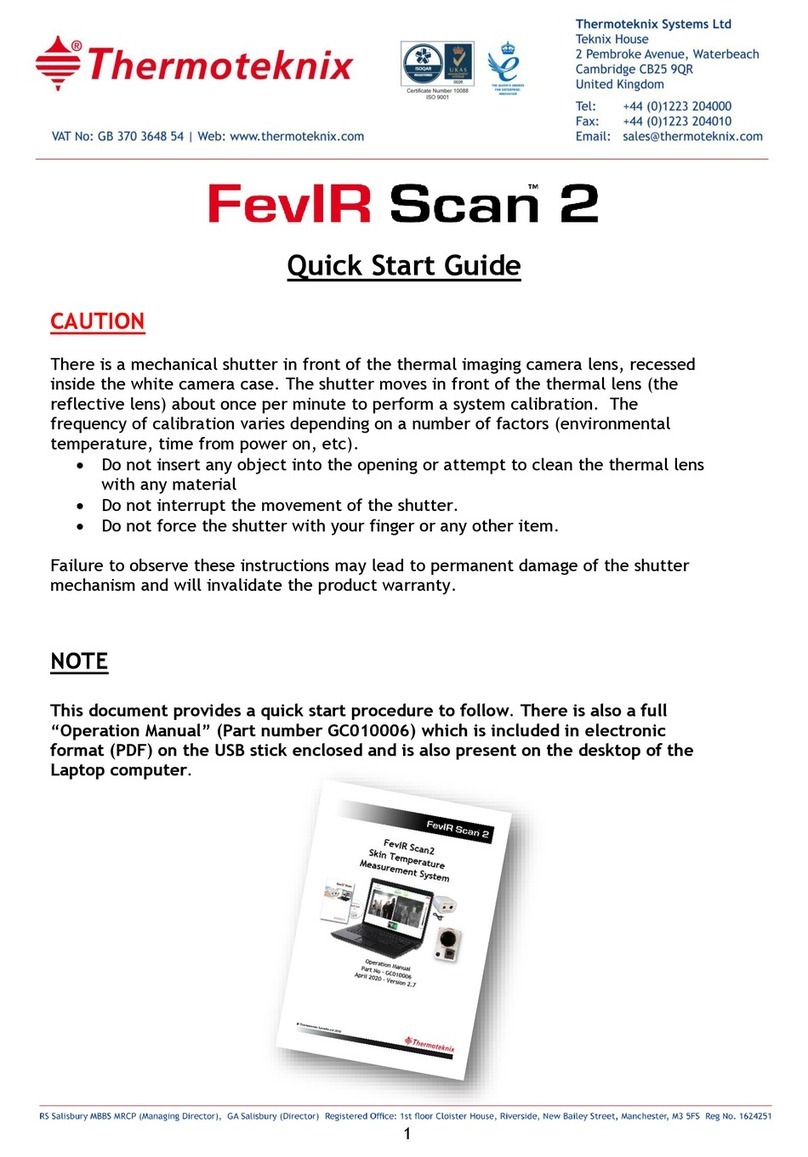
Thermoteknix FevIR Scan2 User manual

© Thermoteknix Systems Ltd 2020
FevIR Scan2
Skin Temperature
Measurement System
Operation Manual
Part No - GC010006
April 2020 - Version 2.7

© Thermoteknix Systems Ltd 2020
Revision history
Date
Version
Notes
24/01/2020
1.0
Document release
16/02/2020
2.0
Document re-write
14/03/2020
2.1
Minor typographical corrections
30/03/2020
2.2
Updated to include FevIR Cam software
06/04/2020
2.3
Updates to match Software release V2.9.3.0
15/04/2020
2.4
Updates to follow QSG guidance (Distance)
16/04/2020
2.5
Added new Blackbody
17/04/2020
2.6
Guidance on distances added
20/04/2020
2.7
Additions and more detailed guidance in line with
ISO standard
23/04/2020
2.8
Formatting corrections

© Thermoteknix Systems Ltd 2020
3
Contents
1FevIR Scan 2 Product Information .................................................................................5
2IMPORTANT NOTICE .........................................................................................................6
3Terminology:.....................................................................................................................9
4Introduction ....................................................................................................................10
4.1 Package checklist .................................................................................................10
4.2 Introduction to FevIR Cam 2 technology ..........................................................11
5Select your monitoring site ..........................................................................................12
6Start monitoring .............................................................................................................14
7Typical Operation...........................................................................................................18
7.1 The alarm image gallery .....................................................................................20
7.2 Defining the screening area: (Setup Menu, F7)...............................................23
7.3 Scanning Area (Setup menu, F7)........................................................................24
7.4 Setting up the image and alarms (Setup menu, F7) .......................................25
7.5 Password ................................................................................................................26
7.6 Setup Menu............................................................................................................27
7.7 Alarm Tab ..............................................................................................................27
7.7.1 Warning Temperature..................................................................................27
7.7.2 Temperatures above the Warning threshold.........................................28
7.7.3 Alarm On/Off delay and Timed Save......................................................28
7.7.4 Saved Image folder....................................................................................28

© Thermoteknix Systems Ltd 2020
4
7.7.5 Alarm Sound................................................................................................28
7.8 Recording Tab .......................................................................................................29
7.9 Display Tab ............................................................................................................30
7.9.1 Current FevIR Cam Location ....................................................................30
7.9.2 Units.............................................................................................................30
7.9.3 Layout..........................................................................................................31
7.9.4 Colour Palette ............................................................................................31
7.9.5 Temperature Labels ..................................................................................31
7.10 The Scanning Tab .................................................................................................32
7.10.1 Scanning Area.............................................................................................32
7.11 The Blackbody Temperature Reference Tab....................................................33
7.11.1 Blackbody reference temperature Marker size and location .............34
7.12 The FevIR Cam Tab ..............................................................................................35
7.13 Saved images.........................................................................................................36
8 Fault Finding .....................................................................................................................37
8.1 Temperature measurement ................................................................................37
8.1.1 Setup the Alarm Threshold value............................................................39
8.2 Shortcuts................................................................................................................40
9Skin temperature measurement ..................................................................................41
10 Labelling .....................................................................................................................43
11 Software installation ................................................................................................44
11.1 Installing FevIR Cam software ............................................................................44
12 Disposal.......................................................................................................................50
13 Support: ......................................................................................................................51

© Thermoteknix Systems Ltd 2020
5
1FevIR Scan 2 Product Information
FevIR Scan 2 is a telethermography system designed to perform initial body
temperature measurement for triage use. The system is intended to measure the
skin temperature of the face and in particular, the temperature of the inner canthus
of the eye, or forehead which are typically 1C (1.6F) below body core temperature.
The detection of an elevated body temperature measurement must be confirmed by
the use of a secondary evaluation methods (e.g., non-contact infrared thermometer
(NCIT) or clinical grade contact thermometer).
A statement of measurement accuracy and calibration are included with each camera
and blackbody reference unit:
The temperature measurement uncertainty (accuracy), is less than or equal to
±0.5°C (±0.9°F) over the temperature range of 34-39°C (93.2-102.2°F)
An accurate, calibrated blackbody ThermaRef 35B1, traceable to UK National
Physical Laboratory (NPL) is included with each system to ensure accuracy of
measurement and correction/compensation of any system drift. It must be installed
in direct line of sight with the camera, equidistant to the subject inspection point
and set to a temperature of 35°C on the unit controller.
The FevIR Scan camera and ThermaRef 35B1 should be left for 15 minutes after
power on to enable both units to stabilise before use.
Both stability and drift are less than 0.2°C (0.36°F) within an 8 hour time frame as
measured and tested by Thermoteknix Systems Ltd. (Data available on request).
The FevIR Scan 2 Camera FSD01 and ThermaRef 35B1 have been tested and certified
to CE and FCC certification including electrical safety and the Low Voltage directive.
The system is supplied with FevIR Scan 2 software installed on a single notebook
computer. The software should be operated in accordance with the guidance in this
Operation Manual.

© Thermoteknix Systems Ltd 2020
6
2IMPORTANT NOTICE
Temperature measurements made using the FevIR Scan 2 system should not be solely
or primarily relied upon to diagnose or exclude a diagnosis of COVID-19 or any other
disease.
An elevated body temperature in the context of use must be confirmed by a suitably
trained person with secondary evaluation methods (e.g., an NCIT or clinical grade
contact thermometer)
Operation of the system must only be carried out with the ThermaRef 35B1
blackbody supplied in operation and placed at the same point (same horizontal
plane) and distance from the camera as the subject inspection point to comply with
system accuracy and performance. The inspection point must be between 1 and 3m
(3.2 to 9.5ft) from the camera. The system self-check and continuous self-test will
show a “System Not Ready” on screen message and a warning triangle which will
prevent system operation if the blackbody is not present, operational, or withing the
field of view.
Only one person at a time must be presented to the camera at the inspection point
The FevIR Scan 2 system has an automatically operated, self-calibrating, Non-
Uniformity Correction (NUC) calibration shutter fitted in front of the thermal lens,
immediately inside the front face of the camera. Do not insert any object into this
opening or attempt to interfere with the operation of the shutter. Any interference
to the operation of the shutter may cause permanent damage to the unit and render
the Manufacturer’s Warranty invalid.
The FevIR Scan 2 camera model FSD01 and the ThermaRef 35B1 units must be re-
calibrated annually from the last date of calibration. This date is shown on the
certificates supplied with the equipment and by a label fixed to each device. Please
contact Thermoteknix for assistance.

© Thermoteknix Systems Ltd 2020
7
The equipment must be set up for subject inspection in a temperature controlled
indoor environment. The location should be free from draughts, heater or air
conditioning ducts, and away from doorways. An environmental temperature
between 20°C and 24°C (68°F to 75°F) and Relative Humidity between 10% and 50%
should be maintained.
Instructions for arranging the camera, blackbody and person screening distance are
detailed in the Instruction Manual and should be observed. It is important that the
subject screening point is aligned with the location of the ThermaRef 35B1 blackbody
to ensure both are at the same distance from the camera focus point (1 –3m, 3.2ft –
9.5ft).
In the event that the equipment must be moved from one location to another, close
down the software on the computer first, then power off each item individually, dis-
connect all cables and return them safely to the heavy-duty transport case provided
with the system. Re-assemble in accordance with the directions stated in the
Instruction Manual.

© Thermoteknix Systems Ltd 2020
8
This equipment is not designed or intended for use as a medical device. This device
is not FDA-cleared or approved. However, as a telethermographic device originally
intended for industrial, construction and commercial use it can be repurposed to
assist in initial screening for fever and triage of individuals in high traffic areas such
as airports and businesses under guidance issued by the US Food and Drug
Administration (FDA).
https://www.fda.gov/media/137079/download
These guidelines are in accordance with ISO Standard:
BS (EN) IEC 80601-2-59:2019
“Safety an essential performance of screening thermographs for human febrile
temperature screening.”
Users should operate the system in accordance with the operating guidelines to
maintain full ISO compliance. These guidelines are given in:
PD ISO/TR 13154:2017
“Deployment, implementation and operational guidelines for identifying febrile
humans using a screening thermograph.”

© Thermoteknix Systems Ltd 2020
9
3Terminology:
The FevIR Scan 2 system employs two key components, these are:
•FevIR Scan Camera;Model FSD01: Referred to throughout this manual as the
“FevIR Camera”.
•ThermaRef Blackbody; Model 35B1: Referred to throughout this manual as
the “Calibration Reference Source”.

© Thermoteknix Systems Ltd 2020
10
4Introduction
4.1 Package checklist
You need to make sure that you have everything for your FevIR Scan system.
Check that you have:
1. FevIR Scan Camera FSD01 (inc. Visible & IR) with power supply
2. Network and USB cables (2m)
3. ThermaRef 35B1 Calibration Reference Source with power supply
4. Laptop
5. FevIR Cam 2 software and Manual on USB stick
Optional items:
1. Tripods for FevIr Cam and Calibration Reference Source
2. Ceiling mounts for FevIR Cam and blackbody

© Thermoteknix Systems Ltd 2020
11
4.2 Introduction to FevIR Cam 2 technology
The Thermoteknix FevIR Cam 2 uses the latest technology of thermal imaging
infrared the FevIR Cam combined with a high-resolution CCD colour visible camera in
a single housing. A blackbody temperature reference unit is a separate device which
maintains its front surface at a constant pre-set temperature and which is accurate
to within ±0.2°C.
The best hand-held type of thermal imaging cameras, when used alone, are very
sensitive to difference in temperature but are only accurate to within ±2°C for
actual temperature so are unable to differentiate between a skin temperature of 37
or 39°C. This makes them wholly unsuitable for use as a fever screening tool.
The Thermoteknix FevIR Cam 1 and FevIR Cam 2 systems include a scientific,
blackbody (termed a “Calibration Reference Source”) within the field of view of the
FevIR Cam. The blackbody reference source is set to 35°C and this enables the FevIR
Cam’s normally achieved ±2°C measurement accuracy to be increased to ±0.2°C
which will determine if a skin temperature is above 37.5°C versus 37.0°C and is
suitable for skin temperature monitoring. This extra accuracy is so important that
the FevIR Cam 2 software constantly monitors the Calibration Reference Source up to
20 times per second and in the event that the Calibration Reference Source is
moved, or the FevIR Cam misaligned or either of the units malfunctioning, then an on
screen alarm is shown and fever screening is paused until the error condition is
resolved.
The Thermoteknix FevIR Cam system cannot be operated without an approved
Calibration Reference Source reference unit in the field of view at all times and with
the calibration software circle tool correctly in position over the centre of the
Calibration Reference Source reference.

© Thermoteknix Systems Ltd 2020
12
5Select your monitoring site
Decide where you want to perform fever monitoring. You need to choose a place
where your subjects can be directed to pass through the FevIR Cam field of view. It
should be possible to move subjects identified by FevIR Cam with an over threshold
temperature from the primary Scanning zone to a private area for confirmation of
core temperature by measurement with a clinical, approved thermometer and
possible isolation.
It is essential that the blackbody is mounted at a fixed location within the field of
view and it is in alignment with the infrared the FevIR Cam and it’s on-screen
calibration circle. This is necessary to ensure that the FevIR Cam temperature
measurement accuracy is maintained at all times. A software function (available on
the setup menu) will check continuously that the FevIR Cam and Calibration
Reference Source are stable and that the calibration circle software tool is correctly
aligned with the Calibration Reference Source. If either of these parameters are not
met (e.g. if the Calibration Reference Source or FevIR Cam the FevIR Cam have been
accidentally moved), a warning triangle and message will be shown on screen and
Scanning will not be available.
The site selected should be free from drafts such as doors or air conditioner vents,
heating radiators or hot machinery, and where the ambient temperature is
reasonably constant and between 20°C and 24°C.
The inspection site should be at a reasonable distance from the exterior of the
building to avoid sudden changes in ambient temperature for subjects entering from
a hot environment to a cold one or vice versa as this causes rapid changes in blood
flow and changes in skin temperature.
Subjects should be requested to remove hats, headgear, eye glasses and facemasks
before proceeding through the checkpoint.
Ropes or gating should be used to keep subjects within the monitoring area. It is not
necessary from a system perspective for subjects to be monitored in single file
although individual monitoring will make the management of the Scanning process a
much easier process.
The Calibration Reference Source needs to be between 1 to 3m distance from the
FevIR Cam the FevIR Cam. Subjects should be measured at the same distance as the
Calibration Reference Source.

© Thermoteknix Systems Ltd 2020
13
To ensure that it is always in the FevIR Cam’s field of view the Calibration Reference
Source can be mounted above the height of the subjects’ heads using a Thermoteknix
FevIR Cam ceiling mount or third-party product. The FevIR Cam must be aligned to
view directly into the draft shield fixed to the front surface of the Calibration
Reference Source.
Alternatively, the Calibration Reference Source can be table or tripod mounted with
the direct line of sight roped off to prevent any person passing between the FevIR
Cam and its direct, unhindered view of the Calibration Reference Source.
The Calibration Reference Source is supplied with a DC power supply for connection
to 110-240VAC mains power. It must be mounted in a location with a stable ambient
temperature, free from draughts and direct sunlight. It is important to ensure that
nothing obstructs the cooling fan located on the side of the device.

© Thermoteknix Systems Ltd 2020
14
6Start monitoring
Setting the system up is straight forward. The supplied laptop has been pre-
configured with the FevIR Cam 2 monitoring software installed and your complete
system has been connected and tested in the factory before shipping to you. Once
you have decided where you want to perform the monitoring, you need to position
the FevIR Cam and Calibration Reference Source, connect the cables and start the
FevIR Cam software.
Installing (or re-installing) the software should not be necessary, but is described
later in this document.
The FevIR Cam head and laptop should be mounted on the FevIR Cam station
platform facing the approaching subjects and with the Calibration Reference Source
temperature reference within the field of view of the FevIR Cam.

© Thermoteknix Systems Ltd 2020
15
The Calibration Reference Source is powered by a 12V DC power supply.
The FevIR Cam is powered by a 5V DC power supply.
Plug in and connect the power cord from the DC power supplies to the respective
Calibration Reference Source unit and the FevIR Cam.
It is recommended to mark the floor at the same distance from the FevIR Cam to the
Calibration Reference Source so that subjects can be checked at a consistent
distance.

© Thermoteknix Systems Ltd 2020
16
The FevIR Cam unit is connected to the laptop using both the network and USB
cables.
The laptop must also be connected to USB, network and power.
The equipment should be turned on for approximately 20 minutes prior to use. The
Calibration Reference Source needs time to stabilise at the required temperature,
and reach thermal equilibrium. This ensures reliable and reproducible temperature
measurement.

© Thermoteknix Systems Ltd 2020
17
To start FevIR Cam software, double-click its desktop icon. The application will start
and assuming the FevIR Cam head is connected and turned on you will see visible and
thermal pictures appearing on the screen. The image appears with an operator
location label in the upper left corner of the screen. The location label can be
changed as required.
A temperature palette bar is located on the right hand side of the image and
determines monochrome, or, false colours used to display the image. The bar is a
typically graduated scale of either black (cold) through to white (hot), or a user
selectable colour palette available for selection on the setup menu All temperatures
measured by the system which are at or below the low point of the temperature
scale are shown in black, or the bottom scale colour, similarly all temperature at the
top or above the top scale value are shown in white, or the top scale colour.
However, all temperatures from the Alarm threshold temperature, which in this case
has been set to 37°C, to the hot upper temperatures are highlighted with a red
isotherm to signify that the temperature represented has reached or exceeded an
alarm condition.
Note the small yellow circle on the infrared image which is located directly onto the
Calibration Reference Source which is mounted on top of the tripod. This is used as
the system reference temperature and provides the necessary temperature
measurement accuracy for the system.

© Thermoteknix Systems Ltd 2020
18
7Typical Operation
A number of screen arrangements can be selected from the setup menu. The side by
side mode is shown here with the visible image on the left and the IR image on the
right.
In this screen arrangement the alarm information is displayed at the top and any
temperatures on the IR image measured above the alarm value will be coloured red.
The actual temperature is shown in a red box adjacent to the subject’s face and will
move with them as they move position in the scene.
Below the threshold temperature and in a larger font. Normally this will be below
the threshold temperature and the font colour will be green. During an alarm
condition the readout will change to red.
Alarm text will also be overlaid on the thermal image, stating “Check subject with an
approved thermometer”. Skin may be unusually hot for reasons other than a fever
(see section 5). Core temperature must be measured to confirm a fever. This must be
taken with a thermometer in a medically approved method, e.g. a tympanic
membrane or oral temperature measuring thermometer.
The software is typically set up to capture a still thermal and visible image when
each alarm condition happens. These are shown in the pair of thumbnail images in
the lower part of the screen. These are always the latest images captured. Warning
text is not overlaid on the stored still images when they are recalled.

© Thermoteknix Systems Ltd 2020
19
To review previous alarm image captures, click on either the folder icon (on the left
of the thumbnail images), or the magnifying glass icon (on the right). This will open a
gallery window showing you the saved alarm images. Use the left and right arrow
keys to scroll back or forwards to earlier/later alarms.

© Thermoteknix Systems Ltd 2020
20
7.1 The alarm image gallery
Selecting the magnifying glass icon opens a window showing one capture at a time,
as below:
The top left and right arrow scroll through captures, sequentially.
The bottom two icons allow image printing and saving for permanent reference.
Images not specifically filed will be sequentially overwritten by new images after the
image buffer is full (typically 20,000 images).
This example shown is purely for illustration and not representative of a clinical
situation. The forced capture was triggered by the heat of a hot drink.
Table of contents
Other Thermoteknix Thermal Camera manuals
