Thermotron 8200 Plus User manual

A Venturedyne, Ltd., Company
8200+ Display Module
Instruction Manual
Revision 0: September 7, 2017
This generic manual is intended for reference purposes only and is not intended to
be used to operate your equipment. For operating instructions and a description of
the features used on your specific control system, see the manual set supplied with
your Thermotron product.
This manual provides the most current generic operating instructions for this
controller at the time of its revision date. Therefore this manual may not include
some recent software changes. This manual also may cover features that are not
available on your current controller. Examples within this manual are for typical
configurations that may not apply to the configuration of your control system.

his generic manual is not intended to be used to operate your equipment.
For additional manuals, contact Thermotron Industries:
Web www.thermotron.com
E-mail info@thermotron.com
Phone Main 616-392-1 91
Product Support 616-392-6550
Marketing 616-393- 580
Fax Product Support 616-393- 5 9
Marketing 616-392-56 3
Address 291 Kollen Park Drive
Holland MI 9 23
USA
Thermotron Industries
A M and Cortex are registered trademarks of A M Limited.
The information in this document is subject to change without notice. No part of this document may be
reproduced or transmitted in any form or by any means, electronic or mechanical, without the express
written permission of Thermotron Industries. Thermotron Industries may have patents or pending patent
applications, trademarks, copyrights, or other intellectual property rights covering subject matter in this
document. The furnishing of this document does not give you license to these patents, trademarks,
copyrights, or other intellectual property except as expressly provided in any written license agreement
from Thermotron Industries.
All relevant issues have been considered in the preparation of this document. Should you notice an
omission or any questionable item in this document, please feel free to contact the Thermotron Product
Support group between 8:00 AM and :30 PM Eastern Standard Time at
616-392-6550.
Regardless of the above statements, Thermotron Industries assumes no responsibility for any errors that
may appear in this document, nor for results obtained by the user as a result of using this product.
Destination Control: These commodities, technology or software when exported from the United States
or re-exported, are subject to Export Administration Regulations (EAR). Diversion contrary to U.S. law is
prohibited.
Revision 0: September 7, 2017

8200+ Display Module Instruction Manual able of Contents
hermotron Industries his generic manual is not intended to be used to operate your equipment. i
able of Contents
Specifications ................................................................................................................................................................................................................... iii
Section 1: Setup
Introduction to the 8200+ display module ..................................................................................................................................................... 1-1
•Using the touch screen ........................................................................................................................................................................... 1-1
•Recommended cleaning procedure .................................................................................................................................................... 1-2
•USB support................................................................................................................................................................................................. 1-2
•File functions ............................................................................................................................................................................................... 1-3
•8200+ file t pes ......................................................................................................................................................................................... 1-3
•Exporting 8200+ data ............................................................................................................................................................................. 1-3
8200+ display controls ............................................................................................................................................................................................. 1-
•Action buttons ............................................................................................................................................................................................ 1-5
•Function buttons ....................................................................................................................................................................................... 1-6
•Changing access levels and passwords ............................................................................................................................................ 1-7
Using the Setup panels ............................................................................................................................................................................................ 1-8
•S stem Setup panel .................................................................................................................................................................................. 1-8
•Control Parameters panel .................................................................................................................................................................. 1-12
•Computer IO panel ................................................................................................................................................................................ 1-13
•Service Messages panel ....................................................................................................................................................................... 1-16
•S stem Events panel ............................................................................................................................................................................. 1-17
•Chan/Aux Names panel ...................................................................................................................................................................... 1-19
Section 2: Operation
Running in manual mode ........................................................................................................................................................................................ 2-1
Program mode operation........................................................................................................................................................................................ 2-3
•Running a program .................................................................................................................................................................................. 2-3
•Programmed c cling................................................................................................................................................................................ 2-6
•Creating or modif ing a program ...................................................................................................................................................... 2-8
Using the Graph panel ........................................................................................................................................................................................... 2-11
•Graph setup .............................................................................................................................................................................................. 2-11
•Navigating the graph ........................................................................................................................................................................... 2-12
Using the Therm-Alarm panels .......................................................................................................................................................................... 2-13
•Therm-Alarm operating modes ........................................................................................................................................................ 2-14
•Positioning the input thermocouple or analog sensor ............................................................................................................ 2-14
•Viewing the Therm-Alarm settings ................................................................................................................................................. 2-15
•Changing the Therm-Alarm settings .............................................................................................................................................. 2-16
•Alarm mute and reset mode functions .......................................................................................................................................... 2-17
•Muting or resetting the Therm-Alarm ........................................................................................................................................... 2-17
•Calibrating a Therm-Alarm ............................................................................................................................................................... 2-17
Section 3: System Information
Monitors panel ............................................................................................................................................................................................................. 3-1
Activity Log panel ....................................................................................................................................................................................................... 3-2
Control Module panel ............................................................................................................................................................................................... 3-3
Computer interface diagnostic panel ................................................................................................................................................................. 3-
System Info panel ....................................................................................................................................................................................................... 3-5

able of Contents 8200+ Display Module Instruction Manual
ii his generic manual is not intended to be used to operate your equipment. hermotron Industries
Section 4: Computer Interface
Overview ......................................................................................................................................................................................................................... -1
•Basic serial communication protocol ................................................................................................................................................ 4-1
•Multidrop address communication protocol (RS-485) ................................................................................................................ 4-1
•GPIB-specific commands........................................................................................................................................................................ 4-2
Command syntax ........................................................................................................................................................................................................ -3
•Quer commands ..................................................................................................................................................................................... 4-3
•Operation commands ............................................................................................................................................................................. 4-3
•Command data formats ......................................................................................................................................................................... 4-3
•Command concatenation ...................................................................................................................................................................... 4-4
Functional command sets ....................................................................................................................................................................................... -
•Control commands ................................................................................................................................................................................... 4-4
•Program status and edit from hold commands ............................................................................................................................ 4-4
•Programming commands ...................................................................................................................................................................... 4-4
•S stem status commands ...................................................................................................................................................................... 4-4
•Variable commands ................................................................................................................................................................................. 4-4
Interface command descriptions .......................................................................................................................................................................... -5
Using the interface command set ..................................................................................................................................................................... - 3
•Using the manual mode variable and control commands .................................................................................................... 4-43
•Using the edit from hold commands .............................................................................................................................................. 4-43
•Using the programming commands .............................................................................................................................................. 4-44
•Using the operation commands to load a program into the 8200+ ................................................................................. 4-45
•Using the quer commands to load a program from the 8200+ ........................................................................................ 4-45
Computer interface troubleshooting and error codes ............................................................................................................................. - 6
•Common computer interface problems and solutions ............................................................................................................ 4-46
•Error codes ................................................................................................................................................................................................ 4-48
Programming examples ........................................................................................................................................................................................ -50
Section 5: CM2 Calibration
Calibration functions ................................................................................................................................................................................................. 5-1
Verifying analog input and analog outputs..................................................................................................................................................... 5-2
Calibrating analog input and analog output channels ............................................................................................................................... 5-3
Adjusting process variable channels................................................................................................................................................................... 5-
Section 6: echnical Information and roubleshooting
Interconnect diagram ................................................................................................................................................................................................ 6-1
Interconnect description .......................................................................................................................................................................................... 6-2
Troubleshooting procedures ................................................................................................................................................................................. 6-3
•S mptom 1: The touch screen displa appears blank ................................................................................................................. 6-3
•S mptom 2: The touch screen does not work, works randoml , or produces incorrect results ................................... 6-3
•Replacing the 8200+ displa module ............................................................................................................................................... 6-3
Appendix A: Glossary
Appendix B: uning Control Parameters
Appendix C: uning P C Control Parameters
Appendix D: 8200+ Parameter and System Event Worksheets
8200+ Display Module Instruction Manual able of Contents
hermotron Industries his generic manual is not intended to be used to operate your equipment. iii
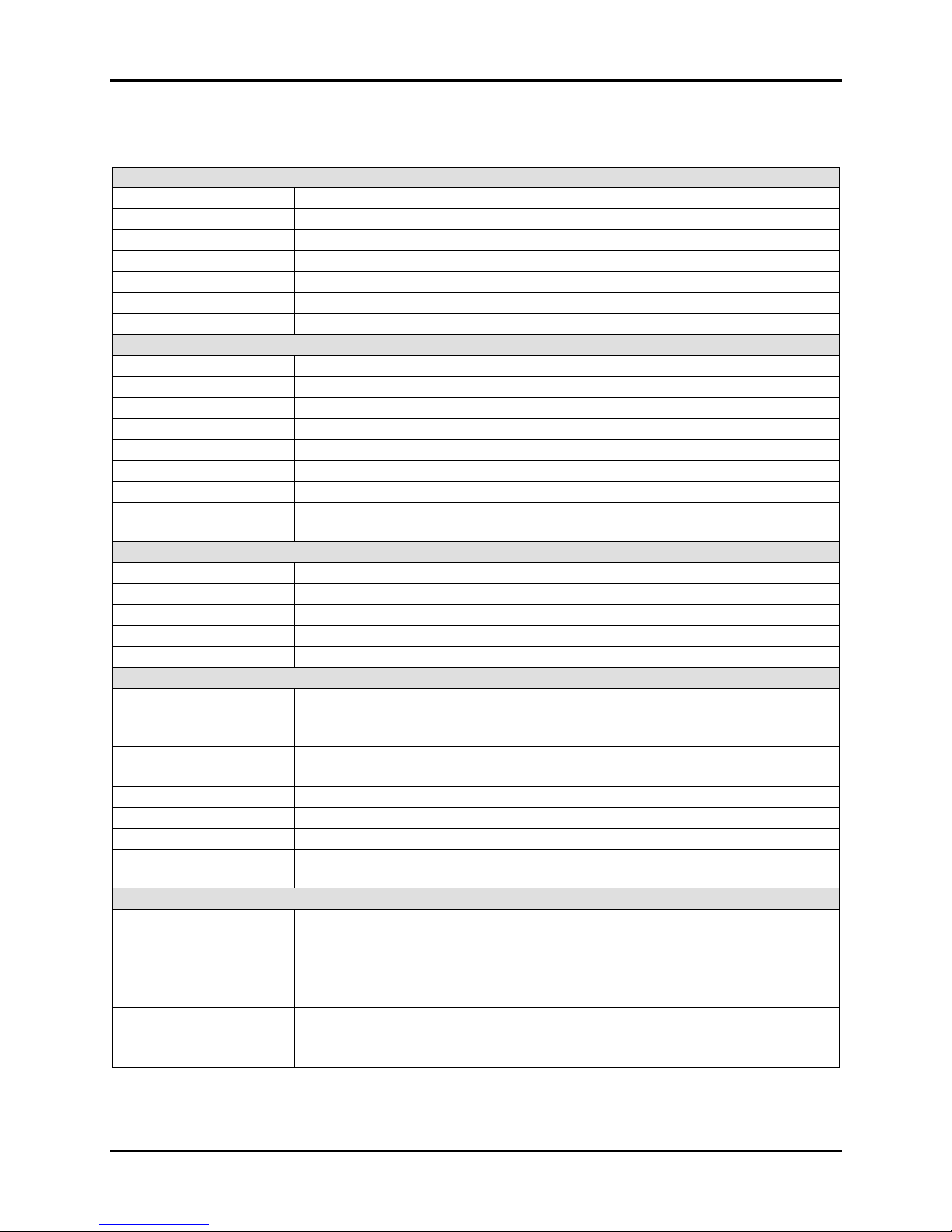
Specifications
Operation
Channels Up to independently programmable channels and single setpoint channels
Temperature range -200°C to + 00°C (-328°F to +725°F)
Measuring accuracy 0.25% of span typical
Temperature scale Celsius or Fahrenheit (user selectable)
Resolution 0.1°C or °F, 0.1% RH, or 0.01 for other linear applications
Sample rate Process variable sampled every 0.25 seconds
Timing Real time clock with month/day/year, hour:minute:second
Programming
Control method Proportional/integral. One of four parameter groups can be selected for each interval.
Proportional band Programmable 1.0 to 9999.0 units
Integral time Programmable 0 to 1,000 seconds
Intervals 300 per program
Interval length One second to 99 hours and 59 minutes, with one-second resolution
Operation Automatic or manual mode
Program storage Limited only by internal storage space
Looping Up to 300 loops can be used per program; loops can be repeated up to 9,999 times;
up to 32 nested loops are allowed per program
Inputs
Control channels Up to 8 ( programmable, single setpoint); thermocouple, RTD, voltage, and current
Digital inputs Up to 2 TTL
Analog inputs Up to 16 available. 0-20 mA or 0-10 Vdc.
Thermocouple inputs Thermocouple (type T, K, E, or J) or RTD
Monitoring channels Up to 16 thermocouple, RTD, voltage, current. 0-20 mA or 0-10 Vdc.
Outputs
Control outputs Proportional-control outputs, 1- to 15-second duty cycle; 0-5 Vdc, 0-20 mA, staged
heating and cooling, bypass, MTO, and system enable; TTL high/low or SSR, up to 32
TTL, 6 SSR (time proportioned/on/off)
Analog outputs Optional analog outputs to send throttles, setpoints, or process variables; 2 standard,
up to 8 current (0 to 20 mA) or voltage (0 to 10 Vdc)
Alarm outputs Process variable, deviation, refrigeration trip
Auxiliary outputs Up to 16 programmable outputs; on/off control per program interval
Auxiliary cooling output Programmable, 0 to 100% of adjustable time frame
System event outputs These outputs can be programmed independently or controlled manually; 2 standard,
up to 16 event outputs available
Graphing and data logging
Graphing mode •6 adjustable display intervals
•Auto scale Y-axis function
•Moveable cursor with automatic data point identification
•Drag and zoom feature
•“Go To” function for historical data fact navigation
Data log mode •All data logged every 6 seconds, approximately a 5-year history
•Export data wizard
•Back-up and restore wizard
able of Contents 8200+ Display Module Instruction Manual
iv his generic manual is not intended to be used to operate your equipment. hermotron Industries
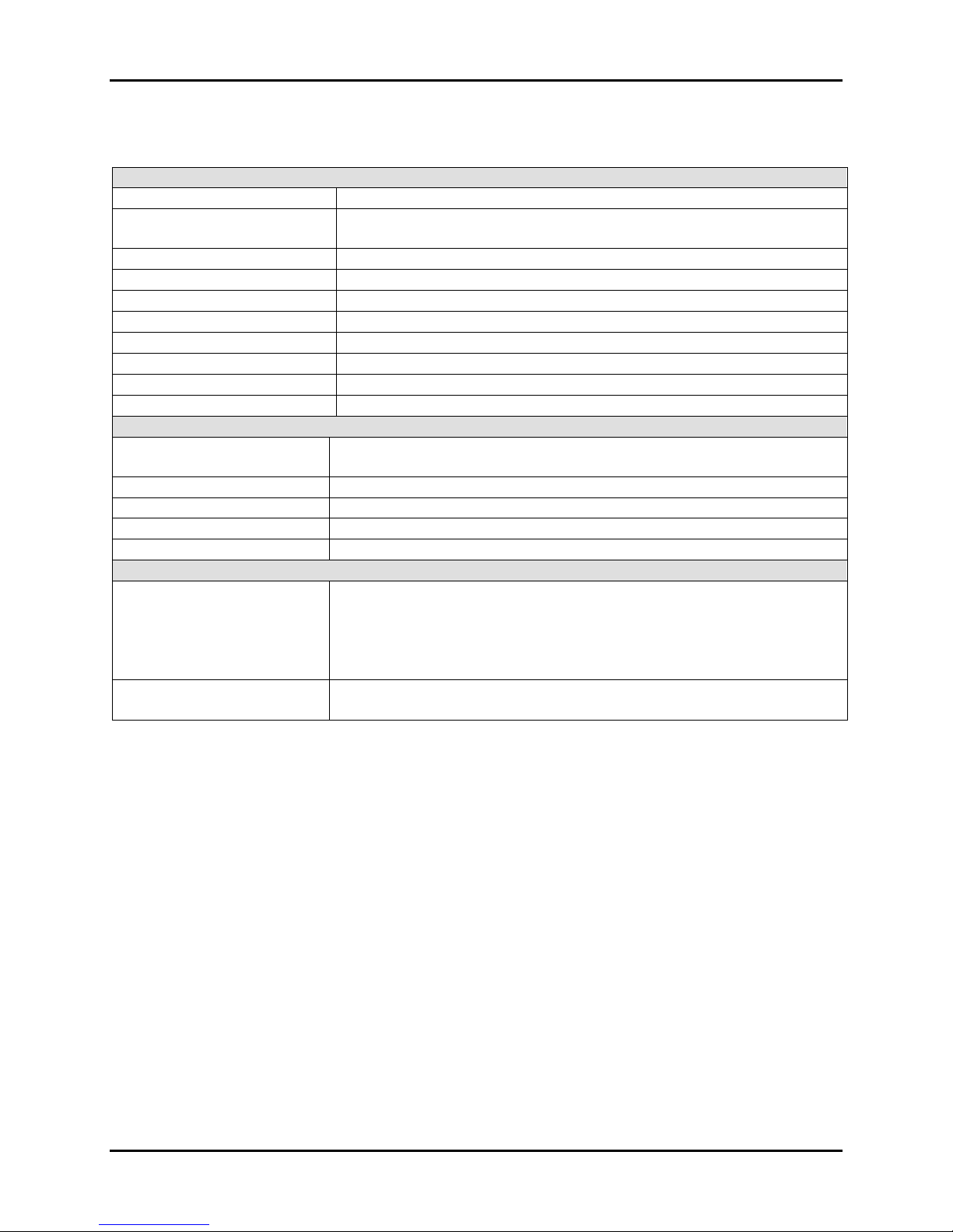
Specifications
Hardware
Operating temperature 0°C to +50°C
Power requirements 95-135 Vac, 7-63 Hertz, 100 volt-amps maximum
12 watts typical, 20 watts maximum
Operating voltage range 18-28 volts (dc)
Open thermocouple protection Deactivates all controller outputs
Program memory Programs are stored on the MSBC micro SD card
Micro SD card GB
RAM 512 MB
Processor 1 GHz ARM
®
Cortex
®
-A8
USB One USB 2.0 port
Ethernet 100 MBps
Display
LCD type 7” (diagonal) widescreen color LCD with touch screen interface
800 x 80 resolution
LCD colors 65,536 (16-bit)
LCD backlight LED backlight
LCD backlight MTBF 20,000 hours
Touch screen type Four-wire resistive
Options
Remote interface Computer I/O:
•Ethernet (TCP/IP) [standard] • RS-232 [optional]
•RS- 85 [optional] • IEEE- 88 [optional]
Web server:
•Ethernet (TCP/IP) [standard]
Optional accessories •Additional control modules for input/output expansion
•Embedded Therm-Alarm(s)
8200+ Display Module Instruction Manual Setup
hermotron Industries his generic manual is not intended to be used to operate your equipment. 1-1
Section 1: Setup
Introduction to the 8200+ display module
NOTE: For information on the CM2 control module, refer to the CM2 Control Module Technical Manual.
The 8200+ display module consists of three main components:
•A miniature single-board computer (MSBC)
•A liquid crystal display (LCD)
The 8200+ motherboard is custom designed to interface with Thermotron’s line of instrumentation. The LCD is a
seven-inch-diagonal widescreen display with an LED backlight and resistive touch capability. For more detailed
information on the 8200+ display module, refer to Section 6 of this manual.
Using the touch screen
The touch screen monitor is the only user input device. To push a button or make a selection, use the supplied stylus
to touch the appropriate area of the monitor screen.
When you touch a specific area of the screen, one of several things could happen:
•The button will remain “in” and perform the desired function. For example, touching the Manual button will
switch the display to the manual mode screen.
•A radio button, check box, or line will be selected. Touching the radio button, check box, or line a second time
will deselect it.
•A drop-down menu will appear, enabling you to make a selection from a list.
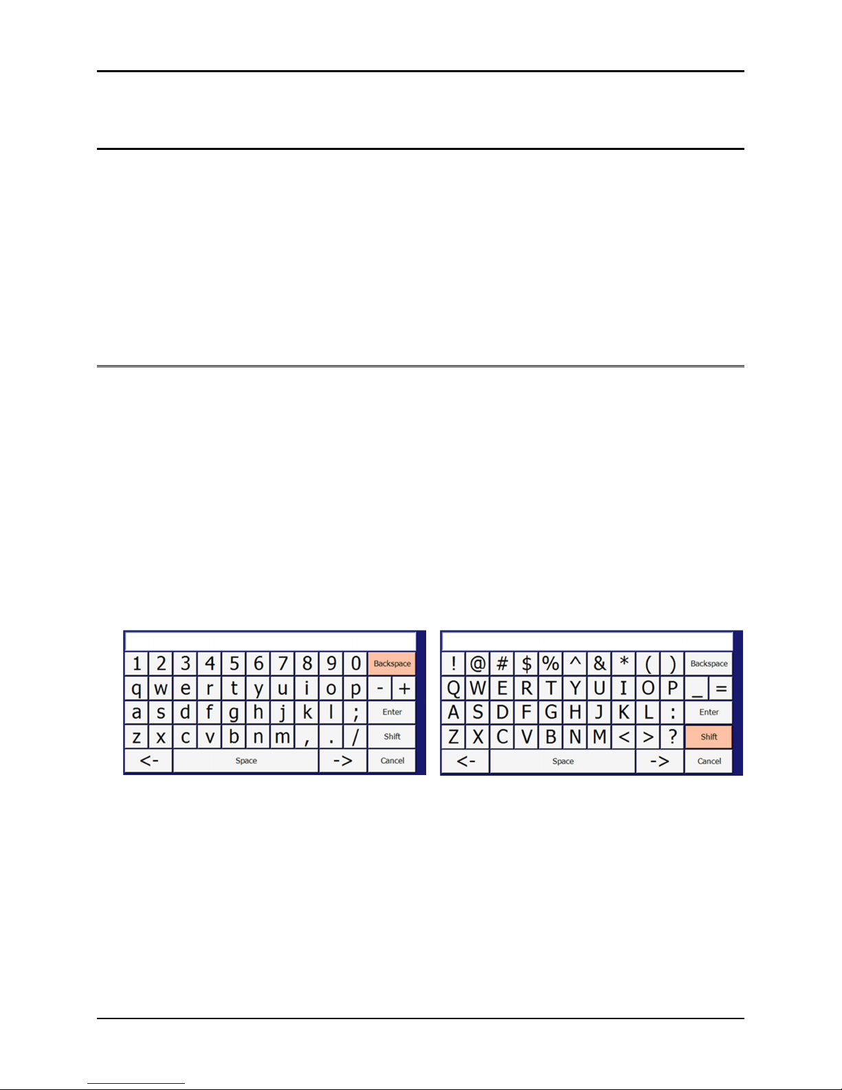
•The alphanumeric keypad will appear. Use the keypad to enter an alphanumeric value into the field. Press Enter
to accept the new value, or press Cancel to close the keypad without entering a new value.
For example, when you touch a channel name field on the Chan/Aux Names panel, the keypad will appear,
indicating that you can enter an alphanumeric value into the field.
The alphanumeric keypad defaults to lowercase letters. To enter uppercase letters or the symbols on the number
keys, press Shift and then the desired letter keys. To return the keypad to lowercase letters, press Shift again.
The Backspace key deletes the character to the left of the cursor. The left and right arrow keys, located on either
side of the Space key, move the cursor to the left and right in the display field at the top of the keypad. The
8200+ will highlight the last key pressed.
Setup 8200+ Display Module Instruction Manual
1-2 his generic manual is not intended to be used to operate your equipment. hermotron Industries
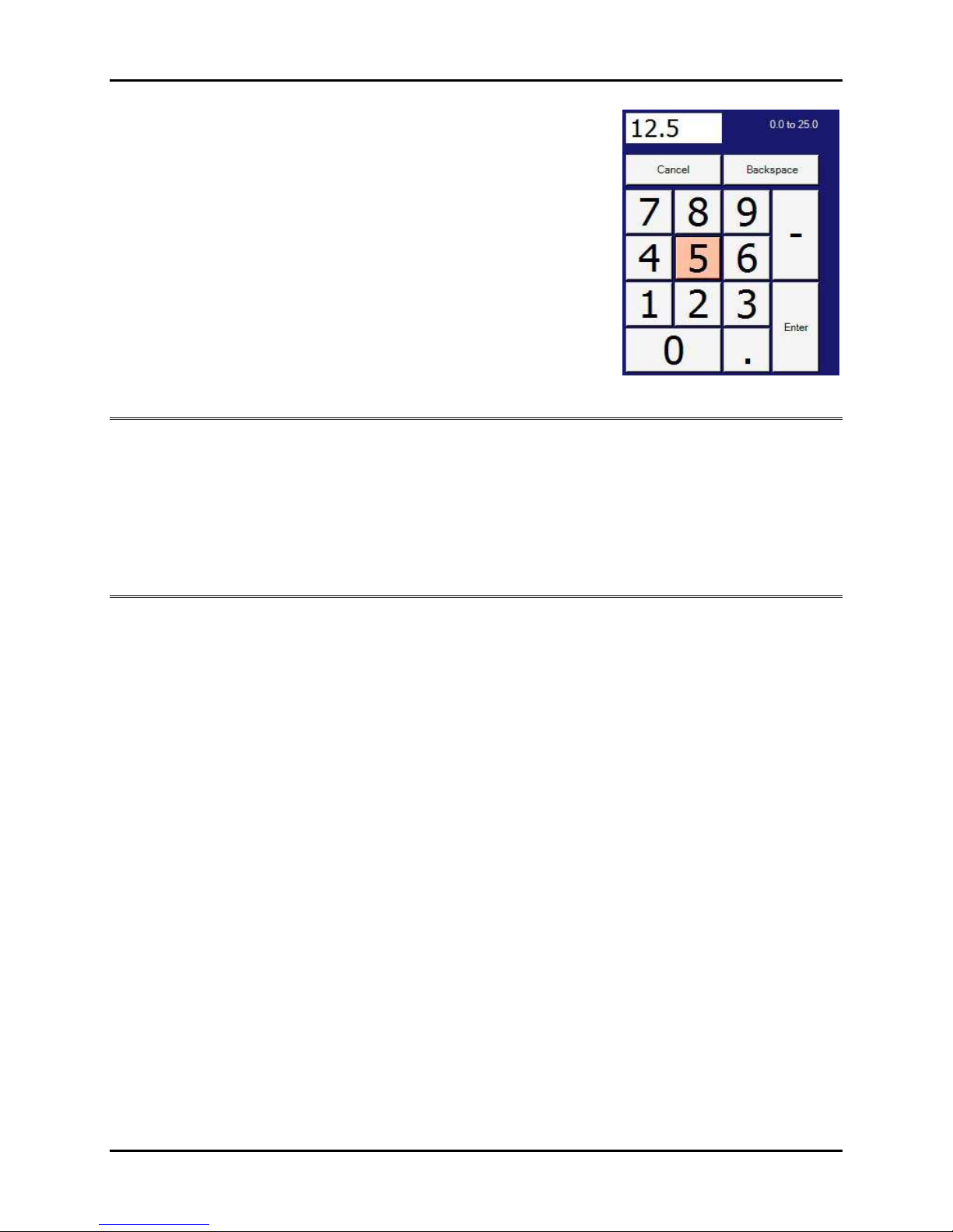
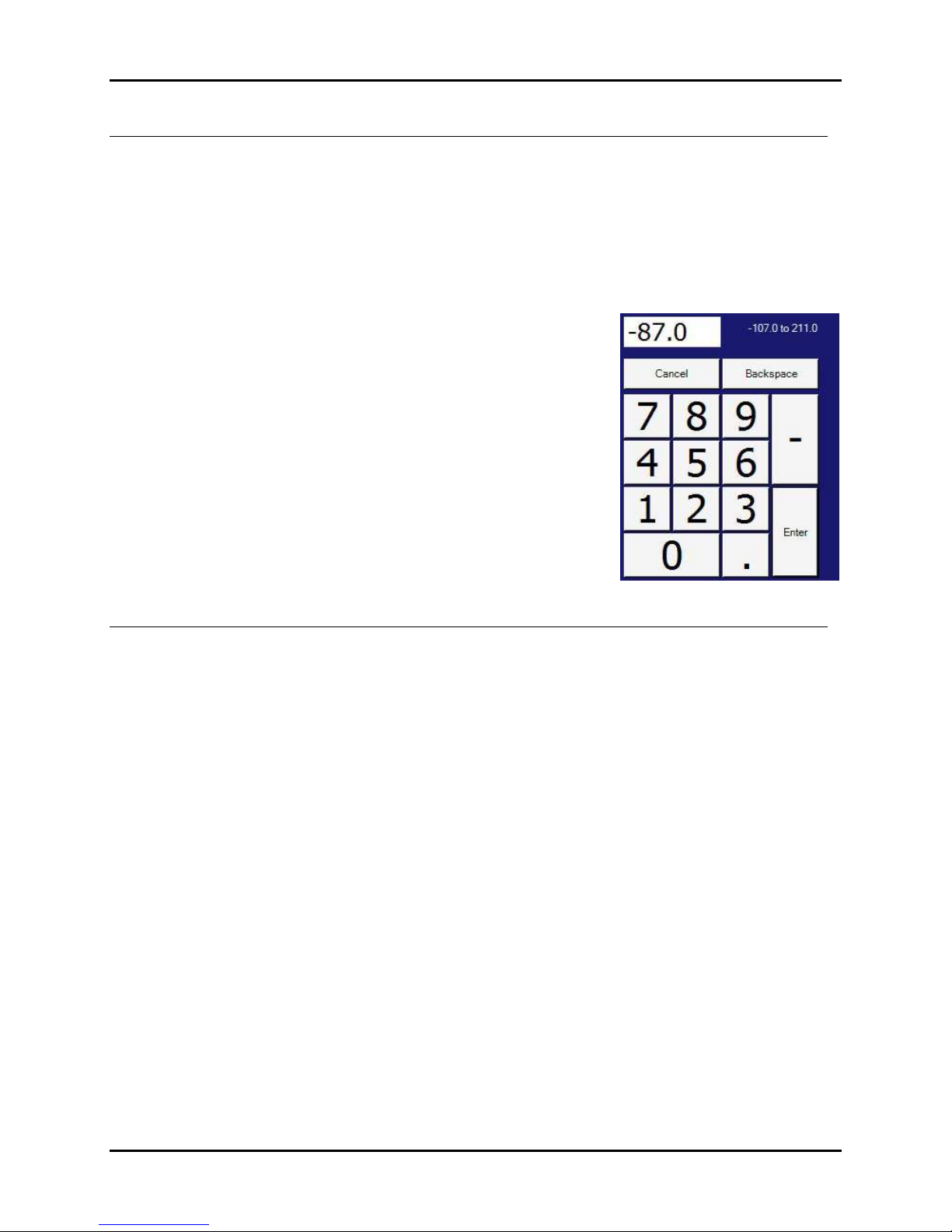
•The numeric keypad will appear. At the top of the keypad is a small display
field as well as an indication of the allowable range of the selected field.
Use the keypad to enter a numeric value into the field.
For example, when you touch the Deviation field on the Program Creation
panel, the numeric keypad will appear, indicating you may enter a value
between 0.0 and 25.0 into the field.
The 8200+ will highlight the last key pressed. Press Enter to accept the new
value, or press Cancel to close the keypad without entering a new value
into the field.
Recommended cleaning procedure
Due to the nature of touch screen interfaces, the surface of the LCD has a tendency to accumulate dirt and
fingerprints, and requires regular cleaning. The surface of the LCD is very durable and resistant to most cleaners, but
the bezel assembly covering the 8200+ is not watertight and precautions should be taken to prevent any liquid or
cleaner from reaching the surface of the electronics behind the bezel. Wiping the LCD with a soft, dry cloth is the best
cleaning procedure, but a liquid glass cleaner may be used to remove stubborn marks. The glass cleaner should be
used to moisten the cloth and the damp cloth used to wipe the display, rather than applying the cleaner directly to
the surface of the LCD.
USB support
USB is included in the 8200+, mainly for the support of USB flash drives. The 8200+ supports all of the most likely
USB devices that would be used with a chamber: flash drives, keyboards, mice, hard drives, floppy drives, etc. Any
flash drive or other storage device connected to the 8200+ must be formatted as FAT32 in order to be recognized by
the operating system.
In addition to the USB driver support limitations in the 8200+, there is also a USB power distribution limitation. A USB
master can provide power to its devices, and the standard allows for two classifications of devices: high power and
low power. High-power devices require up to 500 milliamps of current to operate, and typically are larger devices like
a USB-powered floppy drive. Low-power devices will be more common in 8200+ applications and require no more
than 100 milliamps to operate. Examples of low-power devices are flash drives and anything that has its own power
supply. Due to limitation on the MSBC, the 8200+ can support only one high-power USB device at a time. Multiple
low-power devices may be used with the 8200+.
8200+ Display Module Instruction Manual Setup
hermotron Industries his generic manual is not intended to be used to operate your equipment. 1-3
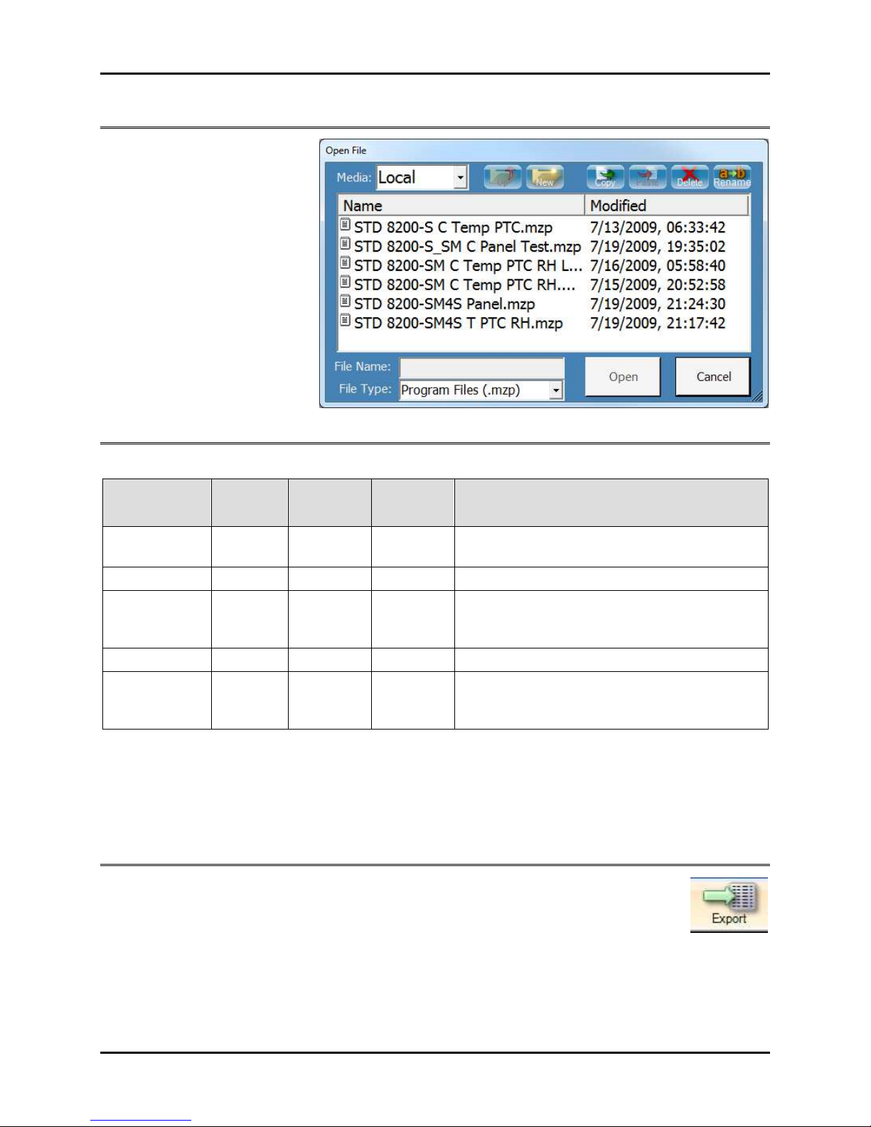
File functions
The 8200+ uses standard Windows
dialog boxes for opening and
saving files (such as program files or
graph settings files). The buttons at
the top of the dialog boxes also
allow you to copy, paste, delete,
and rename files. Files may be
loaded from and saved to the
8200+ micro SD card, a network
drive, or an external USB drive.
8200+ file types
The following table describes the types of files used by the 8200+:
File type File
extension
Access
screen
8200+
functions Description
Chamber data .csv Graph Save Comma-delimited data that can be opened in a
standard spreadsheet program
Graph settings .gvs Graph Save, Open Back up and restore customized graph view settings
Image .png Graph Save
Saves an image file of the current graph. The image
can be opened in a standard graphics program, or
inserted into a standard word processing document.
Program .mzp Program Save, Open Back up and restore an 8200+ program
Control
parameters .prm
Setup/
Control
Parameters
Save, Open Back up and restore control parameter settings
The 8200+ has a virtually unlimited amount of storage space for settings and data. The only limit on the 8200+
storage capacity is the available space on the 8200+ micro SD card ( GB is standard).
NOTE: The 8200+ Backup Wizard helps you create a backup of your programs, settings, and data files so you can
prevent data loss and damage caused by disk failures, power outages, and other potentially damaging events. For
more information, see “System Backup & Recovery” later in this section.
Exporting 8200+ data
Press the Export button to start the Export Data Wizard. This wizard provides step-by-step
instructions for exporting data log files from the 8200+.
Setup 8200+ Display Module Instruction Manual
1-4 his generic manual is not intended to be used to operate your equipment. hermotron Industries
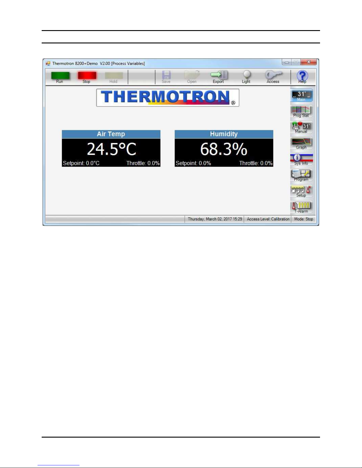
8200+ display controls
The 8200+ display is made up of the following parts:
•The selected screen or panel in the center of the touch screen. The above illustration shows the main screen,
which displays the channel name, current process variable, setpoint, and throttle for each active channel.
•The action buttons, which are always available at the top of the touch screen. For more information, see “Action
buttons” later in this section.
•The function buttons, which are always available along the right side of the touch screen. Function buttons are
used to select the various 8200+ screens and panels. For more information, see “Function buttons” later in this
section.
•The current date, time, access level, and mode of the 8200+ display module. This information is always displayed
at the bottom of the touch screen.

8200+ Display Module Instruction Manual Setup
hermotron Industries his generic manual is not intended to be used to operate your equipment. 1-5
Action buttons
The action buttons are always available at the top of the touch screen. The following paragraphs list the action
buttons and briefly describe their functions.
In the
Manual
screen pressing the
un
button starts running a manual mode test. In any other
screen pressing the un button brings up the un Program Options dialog box. When a test is
running, the green un indicator is lit.
When a test is running, pressing the
Stop
button brings up the
Stop Confirmation
dialog box.
•
To stop the test, press
Yes
. When a test is
stopped, the red Stop indicator is lit.
•To cancel the stop request and continue running
the test, press No.
•To skip the stop confirmation in the future, check
Do not ask this again, or uncheck Confirm Stop
Key on the System Setup panel of the Setup
screen.
When a test is running, pressing the
Hold
button pauses the test and lights the yellow
Hold
indicator. To resume the test at the same point it was paused, press un.
Pressing the
Save
button saves a new or modified file.
Pressing the
Open
button loads a saved file.
The
Save As
button
saves a file under a new name or in a new location.
Pressing the
Export
button starts the
Export Wizard
. This wizard provides step
-
by
-
step instructions
for exporting data log files from the 8200+.
Pressing the
Light
button turns the chamber light on and off. When the chamber light is on, the
button’s yellow light indicator is lit.
Pressing the
Access
button brings up the
Change Access Level
dialog box, allowing you to change
the 8200+ access level and password. For more information, see “Changing access levels and
passwords” later in this section.
Pressing the
Help
button brings up a help topic. The online help system allows you to get help on
many topics relating to the 8200+ control system.

Setup 8200+ Display Module Instruction Manual
1-6 his generic manual is not intended to be used to operate your equipment. hermotron Industries
Function buttons
The function buttons are always available on the right side of the touch screen. The following paragraphs list the
function buttons and briefly describe their functions.
The
Main
screen displays all currently active co
ntrol channels in a large, easy
-
to
-
read format. In
addition to the current value of each channel, the current setpoint and throttle also are displayed.
The
Prog Stat
screen displays the status of the currently running or most recently run program. The
status bar at the top displays the name of the current test as well as its overall progress. (NOTE:
GSoak intervals are not counted towards the overall time). Any active channels for the current interval
appear on the left side of the screen, with the time remaining for the current interval on the right of
the screen. Any options that are enabled are highlighted in the Active Options section.
The
Manual
screen allows you to manually control
chamber
setpoints and options. Whenever any
option is changed, you must press un to commit the changes to the chamber. This allows more than
one setpoint or option to be changed at once. NOTE: Some options prevent other options from
being active at the same time. For example, if PTC is enabled, Humidity will be unavailable until PTC
is unchecked.
The
Graph
screen allows you to view the history of the chamber in a graphical format. Nearly
everything about the chamber is logged to internal storage every six seconds for the entire life of the
controller. Press the Setup button to select what data you wish to view, and also to set up the look
and parameters of the graph. Goto allows you to select any date to jump to immediately, while the
navigation buttons move back and forth one screen at a time. Auto Y will scale the graph to the
current minimum and maximum values of the data on the screen. Cursor allows you to pinpoint the
exact data values of any point in time.
The Sys Info panels provide the following status and diagnostic information:
● Monitor channels ● IO diagnostics
● Activity log ● General system information
● Control module
An
8200+
Program
is made up of a series of intervals that are executed in sequence. Each interval
can have its own set of options configured, including which channels are enabled and which auxiliary
outputs are turned on or off. To enable a guaranteed soak (G-Soak) interval, set the deviation for the
desired channel to non-zero, then check the G-Soak option beneath the time. When the program
reaches this interval, the time will not start counting down until the value of the channel is within the
defined deviation, ensuring the chamber spends the full time span at the desired temperature,
humidity, etc.
The Setup panels allow you to modify the following settings:
● General system setup ● Service messages
● Control parameters ● System events
● Computer IO ● Channel and auxiliary output names
The
T
-
Alarm
panels allow you to set up, view, and calibrate the Therm
-
Alarm.
NOTE
: The
T
-
Alarm
button appears only if your chamber is equipped with one or more Therm-Alarms.
8200+ Display Module Instruction Manual Setup
hermotron Industries his generic manual is not intended to be used to operate your equipment. 1-7
Changing access levels and passwords
The access level function allows you to select from six different levels of access to the 8200+ functions. The following
table provides a general overview of which functions are available at each access level.
Access level Functions available
Locked All functions are locked out. Most information may be viewed but not modified.
Level One Program run, stop, and hold modes are enabled.
Level Two Manual mode operation is enabled.
Programmer Program creation/editing is enabled.
Lab Manager Control parameters and process alarms can be set.
Calibration Calibration and other advanced functions are enabled.
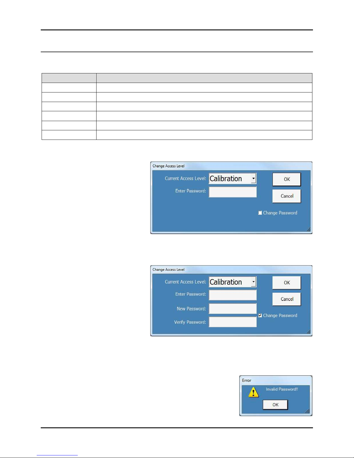
Authorized users can set the access level using a special password. Once the current password is entered, the
authorized user can also select a new password.
1. Press the Access button at the top of
the screen. The Change Access Level
dialog box will appear.
2. To change the access level:
a. Select the desired access level from
the Current Access Level drop-
down menu.
b. If no password has been set, press
OK.
c. If a password has been set, select the Enter Password field, use the alphanumeric keypad to enter the
password, then press OK.
3. To change the password:
a. Select the Change Password check
box. The New Password and Verify
Password fields will appear.
b. If no password has been set, go to
step 3.d.
c. If a password has been set, select
the Enter Password field and use
the alphanumeric keypad to enter
the password.
d. Select the New Password field and use the alphanumeric keypad to enter the new password. Passwords
may consist of up to 20 keystrokes using any keys except Enter and Cancel.
e. Select the Verify Password field and enter the new password again.
f. To accept the new password press OK. To exit without changing the current password press Cancel.
g. If you did not enter the new password correctly, this error message will
appear:
h. Press OK and repeat step c.

Setup 8200+ Display Module Instruction Manual
1-8 his generic manual is not intended to be used to operate your equipment. hermotron Industries
Using the Setup panels
To access the setup panels, press Setup. These panels allow you to configure the 8200+ display
module to meet your specific needs. This section describes the setup panels and how to use them.
System Setup panel
NOTE: To change most settings on the System Setup panel, the 8200+ access level must be Lab Manager or higher.
General Options
Under General Options select a field and enter or modify the setting. For numeric values the keypad will display
the allowable range of the selected field.
•The Time field shows the system date and time, which the 8200+ uses for reference, delayed program start,
and the time stamp for the graph and data logging functions.
•Select the Temperature Scale (Celsius or Fahrenheit) the 8200+ will use to display temperature values.
•The Light Timeout field allows you to enter the number of minutes before the chamber light is
automatically shut off. A value of 0 disables the automatic light shut-off function.
•The Backlight Timeout field allows you to enter the number of minutes of idle time before the 8200+
screen backlight is automatically shut off. A value of 0 disables the backlight timeout function.
•The Language field allows you to select between English and French language user interfaces.
•To disable stop key confirmation, uncheck Confirm Stop Key. This will prevent the Stop Confirmation
dialog box from appearing whenever the Stop button is pressed.
8200+ Display Module Instruction Manual Setup
hermotron Industries his generic manual is not intended to be used to operate your equipment. 1-9
Process Alarms
Each channel of the 8200+ can be set up to activate an alarm if the temperature, humidity, or other process
variable exceeds high or low limits you select. If the variable exceeds the high or low limit, the 8200+ enters stop
mode. Factory-specified limits are programmed into the 8200+. Air and load temperature channel limits typically
are -87°C and +191°C. Humidity channel limits typically are 0 and 100% RH.
CAUTION: It is your responsibility to set process alarm limits appropriate for your product. Process alarms
will not guarantee the safety of your product. To protect your product from temperature extremes, you
must properly configure and use a product protection device such as a Therm-Alarm. If you are testing
expensive products, you should have an additional back-up product protection device.
1. Under Process Alarms select a Low Limit or High Limit field.
2. The numeric keypad will appear. The allowable range of the selected
field appears to the right of the small display field at the top of the
keypad.
3. Enter the desired limit for the channel, then press Enter.
Power Fail Recovery
If the 8200+ is in run or hold mode and a power failure occurs that is longer than the Max Off Time setting, the
8200+ will automatically power up in the mode selected under ecover Mode. If the Max Off Time is set to
0:00:00, this feature is disabled and the 8200+ will power up in whatever mode it was in when power was lost.
1. To enable or disable power fail recovery, check or uncheck the Power Fail ecovery check box.
2. For Max Off Time select the number of hours and minutes power must be lost before the 8200+ enters
power failure recovery mode. The keypad will display the allowable range of each field.
3. From the ecover Mode drop-down menu select a mode to power up in following any power failure that
exceeds the Max Off Time setting. The available settings are:
•Stop: The 8200+ will stop the test that was running when power failed.
•Hold: The 8200+ will hold the test at the point reached when power failed.
•un: The 8200+ will return to the mode it was in when power failed.
•estart: The 8200+ will start running the test again from interval 1.

Setup 8200+ Display Module Instruction Manual
1-10 his generic manual is not intended to be used to operate your equipment. hermotron Industries
Refrigeration Options
.S.A. Time
When running a program, the refrigeration system anticipator time ( .S.A. Time) is the number of minutes the
8200+ will pre-cool the mechanical refrigeration system before entering a zero-time cooling interval (normally a
guaranteed soak). This reduces the lag time caused by cooling the refrigeration hardware.
•Select the .S.A. Time field and enter or modify the setting. The keypad will display the allowable range.
Auxiliary Cooling
Some chambers are equipped with optional liquid nitrogen (LN
2
) or carbon dioxide (CO
2
) auxiliary cooling
systems. When the refrigeration system is operating at full cooling throttle, the auxiliary cooling system can be
operated for a programmed percentage (duty cycle) of a selected time frame.
For example, if you set the auxiliary cooling time frame to five seconds and the duty cycle to 30%, the auxiliary
cooling system comes on for 1.5 seconds (30% of five seconds) and then goes off for the remaining 3.5 seconds
of the five-second interval. If you set the duty cycle to 100, the auxiliary cooling system comes on and stays on
for as long as the refrigeration system is operating at full cooling throttle.
Under Auxiliary Cooling select a field and enter or modify the setting.
•Enter the length of the Time Frame in seconds. The keypad will display the allowable range.
•Enter the percentage of the Duty Cycle.
Humidity emperature Range
NOTE: For your chamber’s humidity temperature range, refer to the specifications listed in your chamber manual.
Under Humidity Temp ange select the High Limit or Low Limit field.
1. The numeric keypad will appear. The keypad will display the allowable range.
2. Enter the temperature limit, then press Enter.
8200+ Display Module Instruction Manual Setup
hermotron Industries his generic manual is not intended to be used to operate your equipment. 1-11
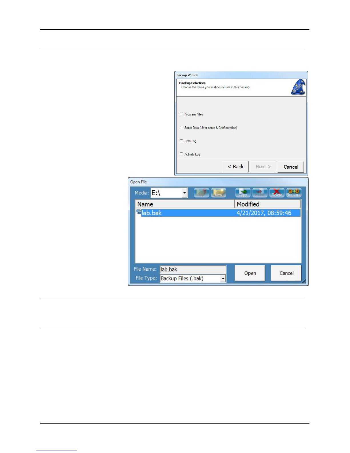
System Backup & Recovery
The Backup Wizard helps you create a backup of your programs, settings, and data files so you can prevent data
loss and damage caused by disk failures, power outages, and other potentially damaging events.
•To start the Backup Wizard, press Backup, then
press Next and follow the step-by-step
instructions.
•To restore previously
backed-up data, press
estore, then use the
Open File dialog box to
find, select, and open the
appropriate backup (.bak)
file.
Input & Output Calibration
The Input & Output Cal buttons function only if the 8200+ access level is Calibration. For calibration
instructions, refer to Section 5: CM2 Calibration in this manual.
Calibrate ouch Screen
To start the touch screen calibration procedure, press Calibrate Touch Screen and follow the on-screen
instructions.
NOTE: To start the calibration procedure from any screen, hold the stylus against the touch screen for 10
seconds.
Setup 8200+ Display Module Instruction Manual
1-12 his generic manual is not intended to be used to operate your equipment. hermotron Industries
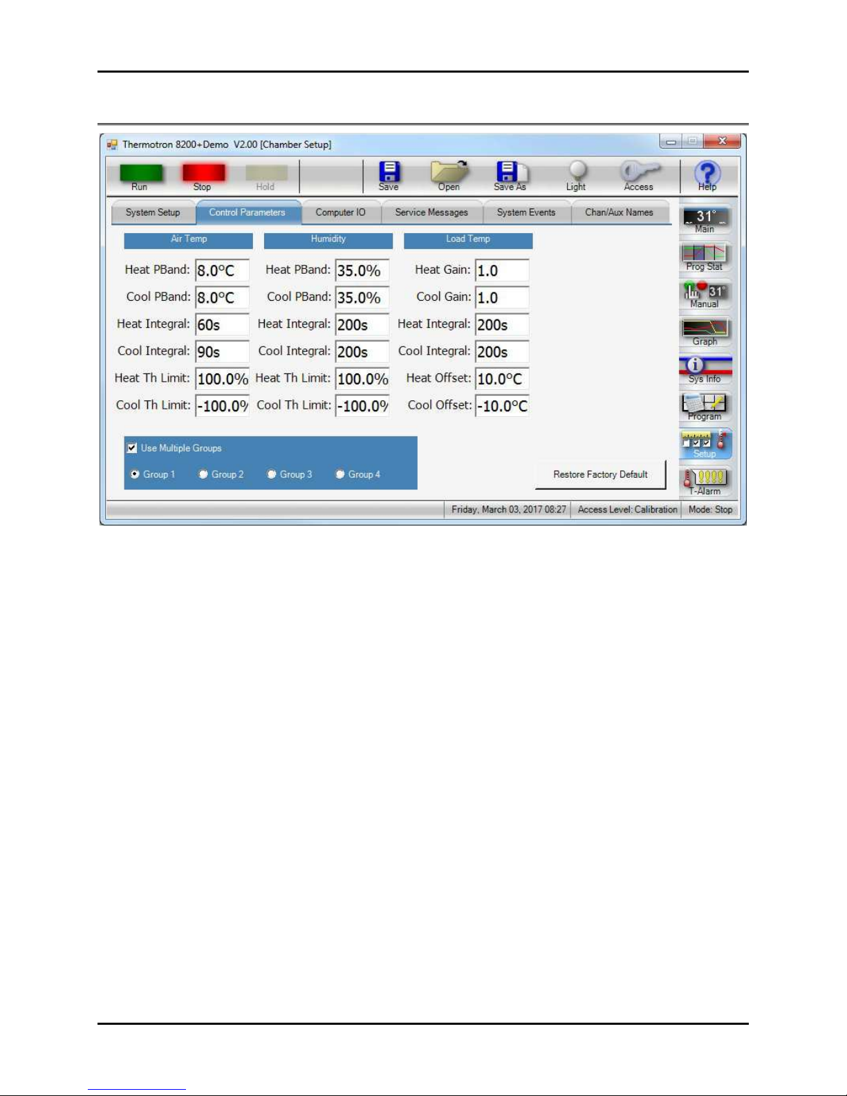
Control Parameters panel
CAUTION: The 8200+ programmer/controller was factory-tuned and should not need to be re-tuned unless
the product requirements change enough to affect the performance of the chamber. Incorrect values could
damage your equipment and/or product.
NOTE: To tune control parameters, the 8200+ access level must be Lab Manager or higher. For information on tuning
the control parameters, see Appendix B. For information on tuning the product temperature control (PTC) control
parameters, see Appendix C.
Control parameters adjust the performance of the chamber around the setpoint. As the chamber nears the setpoint,
the 8200+ adjusts the chamber throttles to provide a smooth ramp to the setpoint. To prevent overshooting and
oscillation around the final setpoint, the refrigeration, heating, and other systems must be damped as they approach
the setpoint. To maximize chamber performance, you must also compensate for lag times.
Up to four groups of chamber parameters can be entered into the 8200+ for each control channel. This allows you to
select chamber performance appropriate for the type of interval or program you are running. For example, in one
interval you may want less control during a ramp between two extreme temperatures, but in the next interval you
may want more control to maintain a constant temperature. To achieve the two levels of control, two groups of
parameters can be programmed.
•To enable multiple groups of control parameters, select the Use Multiple Groups check box.
•To restore the control parameters that were set at the factory, press the estore Factory Defaults button.
8200+ Display Module Instruction Manual Setup
hermotron Industries his generic manual is not intended to be used to operate your equipment. 1-13
Control parameter files
You may also save and load control parameters to and from a file using the Save As and Open buttons. This
provides the ability to save sets of custom control parameters in addition to the four groups already available.
Control parameters files can also be associated with a program such that every time a program runs it will use
the control parameters in a file instead of the currently loaded parameters. To do so you must save a control
parameter file with the same name as the program you wish to associate the parameters with.
For example, if you have a program named Sample Test.mzp, and you save a set of control parameters in a file
named Sample Test.prm, every time you run Sample Test it will automatically use the parameters in the Sample
Test.prm file.
Computer IO panel
NOTE: To change any computer interface setting, the 8200+ access level must be Lab Manager or higher. For more
information on computer interface settings, refer to Section of this manual.
Each 8200+ display module is equipped with two independent computer interface ports. The 8200+ can
communicate through both ports at the same time:
•Network (TCP/IP): Communication through the 8200+ display module’s Ethernet connector. This connector is a
standard eight-pin RJ 5 connector, but only makes use of four pins (two twisted pair). It is intended to enable a
personal computer to communicate with an 8200+ display module over a standard Ethernet network.
•Computer I/O: Communication through the control module com port capable of either RS-232, RS- 85, or GPIB
(IEEE- 88).
The following paragraphs discuss the various communications protocols and how to properly configure the 8200+ to
use them.

Setup 8200+ Display Module Instruction Manual
1-14 his generic manual is not intended to be used to operate your equipment. hermotron Industries
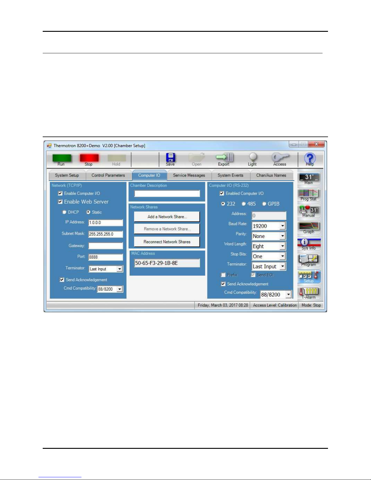
Network ( CP/IP)
The TCP server can handle multiple simultaneous connections. Under Network (TCP/IP) select each field to
modify its setting.
1. Select the Enable Computer I/O check box
2. Select the Enable Web Server check box
3. Select the type of TCP/IP addressing (either DHCP or Static).
. Enter a valid IP Address.
5. Enter a valid Subnet Mask.
6. Enter a valid Gateway address.
7. Enter a valid Port address. NOTE: Thermotron recommends leaving this at the default.
8. Select the desired Terminator.
9. Select the Send Acknowledgement check box. The 8200+ uses the send acknowledgment function to
provide feedback to the computer when it has finished processing a non-query command. When enabled,
the 8200+ will echo back the error code to the host computer when the non-query command has been
processed. This serves two functions:
•When the error code is received by the host computer it knows that the 8200+ has finished processing
the command. If a response has not been received within two seconds, the command should be re-sent.
•A non-zero error code response indicates that the 8200+ did not process the command properly and it
should be re-sent. Without this function, the 8200+ could send commands too fast, causing some
commands to be lost.
10. Select the desired Cmd Compatibility. Command compatibility allows the 8200+ to emulate a legacy
instrument’s command set. For more information see “Legacy instrumentation command compatibility” later
in this section.
Adding and removing network shares
The 8200+ allows you to add a network share.
1. Press the Add a Network Share button. The
Add Network Share dialog box will appear.
2. Enter a valid Share Name.
3. Enter the Network Location in the format
indicated.
. Enter the appropriate User Name and
Password.
5. Press OK.
You can remove a network share at any time by
pressing the emove a Network Share button
and choosing the appropriate share.
Reconnecting network shares
Pressing econnect Network Shares will attempt to reconnect previously added network shares that are
currently disconnected due to a power cycle or other network issue.
Table of contents
Popular Control Unit manuals by other brands

Vixen
Vixen Polar Fine Adjustment Unit DX instruction manual

Silicon Laboratories
Silicon Laboratories Mighty Gecko MGM12P user guide

UNICORECOMM
UNICORECOMM UM220-IV M0 user manual

Pilz
Pilz PSSu E F BSW operating manual

Samson
Samson 33-7 Mounting and operating instructions

Keysight
Keysight N3304A Component level information


Emerson
Emerson Fisher Large ET instruction manual

iWave
iWave iW-RainboW-G20M Hardware user's guide

HEROSE
HEROSE 0651 Series operating instructions

Belkin
Belkin F1DN001R user manual

GORMAN-RUPP
GORMAN-RUPP GRP33-08A Installation, operation, and maintenance manual with parts list

Microhard Systems
Microhard Systems Nano Series operating manual