Samson 33-7 Service manual

Translation of original instructions
EB 2551-2 EN
Type33-7 Safety Excess Pressure Valve (SEV)
Self-operated Regulators
Edition July 2020

Note on these mounting and operating instructions
These mounting and operating instructions assist you in mounting and operating the device
safely. The instructions are binding for handling SAMSON devices. The images shown in
these instructions are for illustration purposes only. The actual product may vary.
ÎFor the safe and proper use of these instructions, read them carefully and keep them for
later reference.
ÎIf you have any questions about these instructions, contact SAMSON‘s After-sales Service
(aftersalesservice@samsongroup.com).
The mounting and operating instructions for the devices are included
in the scope of delivery. The latest documentation is available on our
website at www.samsongroup.com > Service & Support > Downloads >
Documentation.
Definition of signal words
Hazardous situations which, if not avoided,
will result in death or serious injury
Hazardous situations which, if not avoided,
could result in death or serious injury
Property damage message or malfunction
Additional information
Recommended action
DANGER
!
WARNING
!
NOTICE
!
Note
Tip
EB 2551-2 EN

Contents
EB 2551-2 EN 1
1 Safety instructions and measures ................................................................1-1
1.1 Notes on possible severe personal injury ......................................................1-4
1.2 Notes on possible personal injury ................................................................1-5
1.3 Notes on possible property damage.............................................................1-7
2 Markings on the device ..............................................................................2-1
2.1 Nameplate .................................................................................................2-1
2.2 Location of the nameplate............................................................................2-1
2.3 Material numbers........................................................................................2-1
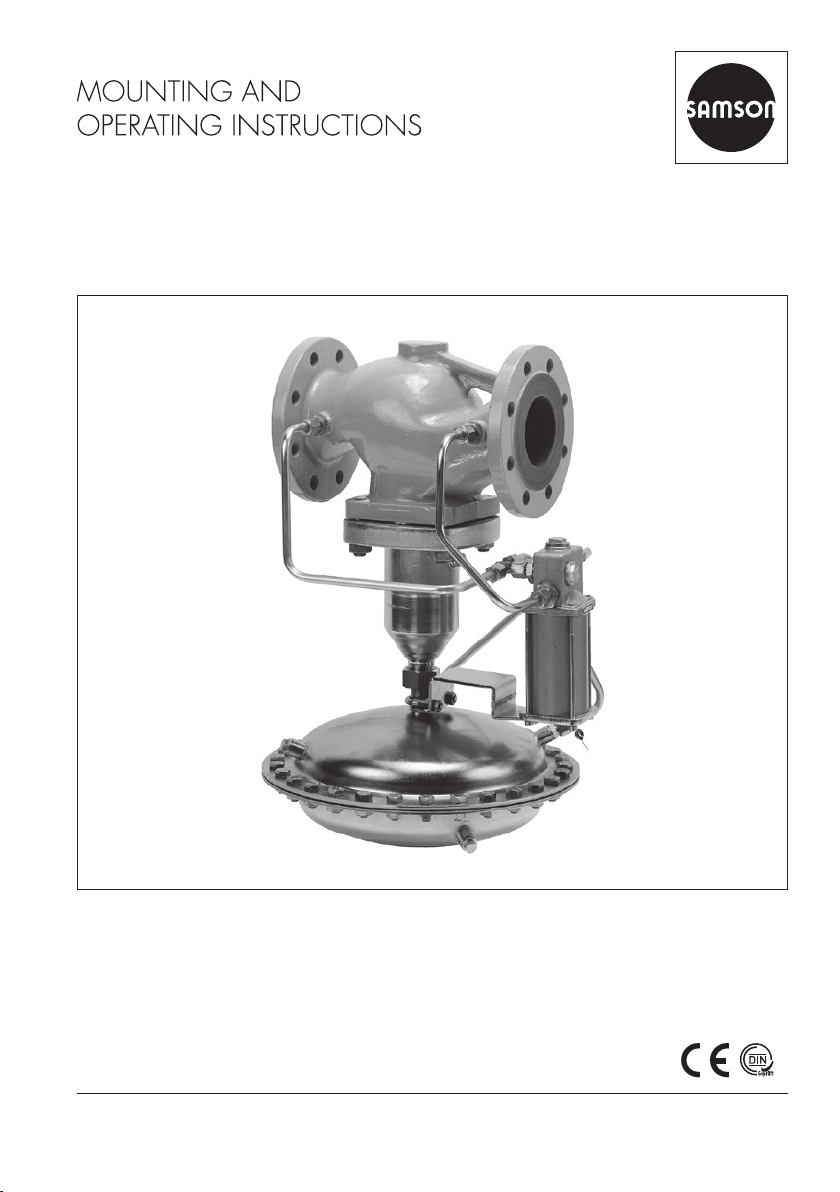
3 Design and principle of operation ...............................................................3-1
3.1 Additionalttings........................................................................................3-3
3.2 Technical data ............................................................................................3-4
4 Shipment and on-site transport ...................................................................4-1
4.1 Accepting the delivered goods .....................................................................4-1
4.2 Removing the packaging from the regulator ..................................................4-1
4.3 Transporting and lifting the regulator............................................................4-2
4.3.1 Transporting the regulator............................................................................4-2
4.3.2 Lifting the regulator .....................................................................................4-3
4.4 Storing the regulator ...................................................................................4-4
5 Installation.................................................................................................5-1
5.1 Installation conditions..................................................................................5-1
5.2 Preparation for installation...........................................................................5-3
5.3 Final installation..........................................................................................5-4
5.3.1 Installing the regulator.................................................................................5-4
5.3.2 Cleaning the pipeline ..................................................................................5-4
5.4 Testing the regulator ....................................................................................5-5
5.4.1 Leak test.....................................................................................................5-6
5.4.2 Pressure test................................................................................................5-6
5.5 Insulation ...................................................................................................5-7
6 Start-up .....................................................................................................6-1
6.1 Start-up and putting the device back into operation .......................................6-2
6.2 Starting up the plant....................................................................................6-2
7 Operation..................................................................................................7-1
7.1 Adjusting the set point.................................................................................7-1

Contents
2 EB 2551-2 EN
8 Malfunctions ..............................................................................................8-1
8.1 Troubleshooting ..........................................................................................8-1
8.2 Emergency action .......................................................................................8-2
9 Servicing....................................................................................................9-1
9.1 Preparing the valve for service work.............................................................9-2
9.2 Installing the regulator after service work ......................................................9-2
9.3 Service work...............................................................................................9-2
9.3.1 Cleaningorreplacingthelterinthepilotvalve............................................9-2
9.3.2 Replacing the seat and plug.........................................................................9-4
9.3.3 Replacing the actuator's operating diaphragm ..............................................9-4
9.4 Ordering spare parts and operating supplies ................................................9-4
10 Decommissioning .....................................................................................10-1
11 Removal ..................................................................................................11-1
11.1 Removing the regulator from the pipeline....................................................11-1
12 Repairs ....................................................................................................12-1
12.1 Returning devices to SAMSON ..................................................................12-1
13 Disposal...................................................................................................13-1
14 Certicates...............................................................................................14-1
15 Annex......................................................................................................15-1
15.1 Tightening torques.....................................................................................15-1
15.2 Lubricant..................................................................................................15-1
15.3 Tools ........................................................................................................15-1
15.4 Accessories ..............................................................................................15-1
15.5 Spare parts ..............................................................................................15-2
15.6 After-sales service.....................................................................................15-2

EB 2551-2 EN 1-1
Safety instructions and measures
1 Safety instructions and measures
Intended use
TheSAMSONType33-7Regulatorisasafetyexcesspressurevalve(SEV).
The self-operated regulator is used to control the upstream pressure p1in the pipeline to the
adjusted set point. Liquids and gases in processing and industrial plants can be controlled by
the regulator.
Theregulatorisdesignedtooperateunderexactlydenedconditions(e.g.operating
pressure, process medium, temperature). Therefore, operators must ensure that the regulator
isonlyusedinoperatingconditionsthatmeetthespecicationsusedforsizingtheregulator
at the ordering stage. In case operators intend to use the regulator in other applications or
conditionsthanspecied,contactSAMSON.
SAMSON does not assume any liability for damage resulting from the failure to use the de-
viceforitsintendedpurposeorfordamagecausedbyexternalforcesoranyotherexternal
factors.
ÎRefertothetechnicaldataandnameplateforlimitsandeldsofapplicationaswellas
possible uses.
Reasonably foreseeable misuse
The regulator is not suitable for the following applications:
− Useoutsidethelimitsdenedduringsizingandbythetechnicaldata
− Useoutsidethelimitsdenedbytheadditionalttingsmountedontheregulator
Furthermore, the following activities do not comply with the intended use:
− Use of non-original spare parts
− Performing service and repair work not described
− ModicationofpartsaswellasserviceorrepairworkonTÜV-testedtheType33-7
Qualications of operating personnel
The regulator must be mounted, started up, serviced and repaired by fully trained and
qualiedpersonnelonly;theacceptedindustrycodesandpracticesmustbeobserved.
According to these mounting and operating instructions, trained personnel refers to
individualswhoareabletojudgetheworktheyareassignedtoandrecognizepossible
hazardsduetotheirspecializedtraining,theirknowledgeandexperienceaswellastheir
knowledge of the applicable standards.

1-2 EB 2551-2 EN
Safety instructions and measures
Safety features
TheType33-7Regulatorisasafetyexcesspressurevalve(SEV).Whenrelievedofpressure,
the regulator is closed by the force of the positioning springs.
Personal protective equipment
Werecommendcheckingthehazardsposedbytheprocessmediumbeingused(e.g.
uGESTIS(CLP)hazardoussubstancesdatabase).Dependingontheprocessmediumand/
or the activity, the protective equipment required includes:
− Protectiveclothing,safetyglovesandeyeprotectioninapplicationswithhot,coldand/or
corrosive media
− Wearhearingprotectionwhenworkingnearthevalve
− Hard hat
− Safety harness when working at height
− Safetyfootwear,ESD(electrostaticdischarge)footwear,ifnecessary
ÎCheck with the plant operator for details on further protective equipment.
Revisions and other modications
Revisions,conversionsorothermodicationsoftheproductarenotauthorizedbySAMSON.
Theyareperformedattheuser'sownriskandmayleadtosafetyhazards,forexample.
Furthermore, the product may no longer meet the requirements for its intended use.
Warning against residual hazards
To avoid personal injury or property damage, plant operators and operating personnel must
preventhazardsthatcouldbecausedintheregulatorbytheprocessmedium,theoperating
pressure or by moving parts by taking appropriate precautions. Plant operators and operat-
ingpersonnelmustobserveallhazardstatements,warningandcautionnotesinthese
mounting and operating instructions.
Hazardsresultingfromthespecialworkingconditionsattheinstallationsiteoftheregulator
mustbeidentiedinariskassessmentandpreventedthroughthecorrespondingsafetyin-
structions drawn up by the operator.
Wealsorecommendcheckingthehazardsposedbytheprocessmediumbeingused(e.g.
uGESTIS(CLP)hazardoussubstancesdatabase).
ÎObservesafetymeasuresforhandlingthedeviceaswellasrepreventionandexplosion
protection measures.

EB 2551-2 EN 1-3
Safety instructions and measures
Responsibilities of the operator
Operators are responsible for proper operation and compliance with the safety regulations.
Operators are obliged to provide these mounting and operating instructions as well as the
referenced documents to the operating personnel and to instruct them in proper operation.
Furthermore,operatorsmustensurethatoperatingpersonnelorthirdpartiesarenotexposed
to any danger.
Responsibilities of operating personnel
Operating personnel must read and understand these mounting and operating instructions as
wellasthereferenceddocumentsandobservethespeciedhazardstatements,warnings
and caution notes. Furthermore, operating personnel must be familiar with the applicable
health, safety and accident prevention regulations and comply with them.
Theoperatorisadditionallyresponsibleforensuringthatthelimitsfortheproductdenedin
the technical data are observed. This also applies to the start-up and shutdown procedures.
Start-up and shutdown procedures fall within the scope of the operator's duties and, as such,
are not part of these mounting and operating instructions. SAMSON is unable to make any
statements about these procedures since the operative details (e.g. differential pressures and
temperatures) vary in each individual case and are only known to the operator.
Referenced standards and regulations
TheregulatorscomplywiththerequirementsoftheEuropeanPressureEquipmentDirective
2014/68/EU.RegulatorswithaCEmarkinghaveanEUdeclarationofconformity,which
includes information about the applied conformity assessment procedure. This EU declaration
ofconformityisincludedinthe'Certicates'section.
AccordingtotheignitionriskassessmentperformedinaccordancewithEN13463-1:2009,
section 5.2, the non-electrical regulators do not have their own potential ignition source even
in the rare incident of an operating fault. As a result, they do not fall within the scope of
Directive2014/34/EU.
ÎForconnectiontotheequipotentialbondingsystem,observetherequirementsspeciedin
section6.4ofEN60079-14(VDE0165-1).

1-4 EB 2551-2 EN
Safety instructions and measures
1.1 Notes on possible severe personal injury
DANGER
!
Risk of bursting in pressure equipment.
Regulators and pipelines are pressure equipment. Impermissible pressure or improper
opening can lead to regulator components bursting.
ÎObservethemaximumpermissiblepressureforregulatorandplant.
ÎBeforestartinganyworkontheregulator,depressurizeallplantsectionsaffected
as well as the regulator.
ÎDraintheprocessmediumfromalltheplantsectionsaffectedaswellasthe
regulator.
ÎWearpersonalprotectiveequipment.
Referenced documentation
The following documents apply in addition to these mounting and operating instructions:
− Mounting and operating instructions for
e.g. Type2N/NI Strainer uEB1015
− Datasheetsfor
e.g. Type2N/NI Strainer uT1015
− Mountingandoperatinginstructionsaswellasdatasheetsforadditionalttings
(e.g. shut-off valves, pressure gauges etc.).

EB 2551-2 EN 1-5
Safety instructions and measures
1.2 Notes on possible personal injury
WARNING
!
Risk of personal injury through incorrect operation, use or installation as a result of
information on the regulator being illegible.
Over time, markings, labels and nameplates on the regulator may become covered
withdirtorbecomeillegibleinsomeotherway.Asaresult,hazardsmaygounno-
ticed and the necessary instructions not followed. There is a risk of personal injury.
ÎKeep all relevant markings and inscriptions on the device in a constantly legible
state.
ÎImmediately renew damaged, missing or incorrect nameplates or labels.
Risk of hearing loss or deafness due to loud noise.
The noise emissions depend on the valve version, plant facilities and process medium.
ÎWearhearingprotectionwhenworkingnearthevalve.
Risk of personal injury due to pressurized components and process medium being
discharged.
Incorrect opening of pressure equipment or mounting parts may lead to the process
medium escaping to the atmosphere.
ÎDonotloosenthecontrollinewhilethevalveispressurized.
Risk of burn injuries due to hot or cold components and pipelines.
Dependingontheprocessmedium,regulatorcomponentsandpipelinesmaygetvery
hot or cold and cause burn injuries.
ÎAllow components and pipelines to cool down or warm up to the ambient tempera-
ture.
ÎWearprotectiveclothingandsafetygloves.

1-6 EB 2551-2 EN
Safety instructions and measures
WARNING
!
Damage to health relating to the REACH regulation.
If a SAMSON device contains a substance which is listed as being a substance of very
high concern on the candidate list of the REACH regulation, this circumstance is indi-
cated on the SAMSON delivery note.
ÎInformation on safe use of the part affected uwww.samsongroup.com/en/
about-samson/material-compliance/reach-regulation/
Risk of personal injury due to residual process medium in the regulator.
Whileworkingontheregulator,residualprocessmediumcanescapeand,depending
on its properties, may lead to personal injury, e.g. (chemical) burns.
ÎIf possible, drain the process medium from all the plant sections affected and the
regulator.
ÎWearprotectiveclothing,safetyglovesandeyeprotection.

EB 2551-2 EN 1-7
Safety instructions and measures
1.3 Notes on possible property damage
NOTICE
!
Risk of regulator damage due to incorrectly attached slings.
ÎDonotattachload-bearingslingstotheactuatorhousing.
Risk of regulator damage due to unsuitable medium properties.
Theregulatorisdesignedforaprocessmediumwithdenedproperties.
ÎOnlyusetheprocessmediumspeciedforsizing.
Risk of regulator damage due to contamination (e.g. solid particles) in the pipeline.
The plant operator is responsible for cleaning the pipelines in the plant.
ÎFlush the pipelines before start-up.
SAMSON's After-sales Service can support you concerning lubricant, tightening torques
and tools approved by SAMSON.
Note

1-8 EB 2551-2 EN

EB 2551-2 EN 2-1
Markings on the device
2 Markings on the device
2.1 Nameplate
21347
9111310 128
Var.-IDK
VS m³/h
PN DN
bar
°C
56
14
DIN/ANSI version
1 Type
2 Pressure rating in PN
3 Material number
4ValvesizeinDN
5 Perm. temperature in °C
6 KVScoefcient
7 Body material
8TÜVregistrationnumber
9 p1or p2
10 Set point range
11 Order number
12 SAP number
13 QR code
14 Dateofmanufacture
Fig.2-1: Regulator nameplate
2.2 Location of the nameplate
Location of the
nameplate
Fig.2-2: Nameplate of Type33-7 Regulator
2.3 Material numbers
The material designation can be found on
the nameplate (7, body material) or you can
contactus(thecongurationIDspecication
isneeded)tondoutwhichmaterialisused.
Thisisspeciedonthenameplateinthe
'MNo'eld(3).Formoredetailsonthe
nameplate,seesection2.1.

2-2 EB 2551-2 EN

EB 2551-2 EN 3-1
Design and principle of operation
3 Design and principle of oper-
ation
ÎSeeFig.3-1
TheType33-7ExcessPressureValve(SEV)
consists of the main valve with actuator and
the pilot valve attached to it.
Thesafetyexcesspressurevalveisusedto
maintain the pressure upstream of the main
valve to a set point adjusted at the pilot
valve.
Thesafetyexcesspressurevalveopensasthe
upstream pressure p1rises.
Whenthesafetyexcesspressurevalvestarts
toopen,theprocessmediumrstows
through the pilot valve (8) before the main
valve(1)opens.Duringwhich,theforces
acting on the plug in the main valve are
eliminated by the balancing bellows (5).
The upstream pressure p1is fed through the
control line (10) to the pilot valve (8). The
pilot valve (8) creates a control pressure pS. It
functionsasanexcesspressurevalveand
controls the main valve (1).
The control pressure pSis transferred through
the control line (12) and acts on the operat-
ing diaphragm (6).
The control pressure pSdrops when the
upstream pressure p1rises. The force
resulting from the control pressure pSacting
on the operating diaphragm (6) and the
forces created at the positioning springs (7)
fall below the force of the prevailing
upstream pressure p1. The main valve (1)
opens.
A decrease in upstream pressure p1causes
the control pressure pSto rise. As a result,
the control pressure pSgradually reaches the
same level of the upstream pressure p1
causing the main valve (1) to be closed by
the positioning springs (7).
Upon failure of the operating diaphragm (6),
thesafetyexcesspressurevalveopensand
the pressure falls below the adjusted pres-
sure p1.
To ensure proper functioning of the regulator,
the minimum differential pressure Δpmin must
correspond to the pressure specied in Table
3-1.
Note

3-2 EB 2551-2 EN
Design and principle of operation
10
10.1
1
2
3
11
6
7
p1
p2
p1
pS
p1
p2
pS
12
4
58
8.1
8.2
9
1Main valve
2Seat
3Plug
4Plug stem
5Balancing bellows
6Operating diaphragm
7Positioning springs
8Pilot valve
8.1 Filter
8.2 Set point springs
9Set point adjuster
10 Control line for upstream pressure p1
10.1 Control line for upstream pressure p1
11 Control line for downstream pressure p2
12 Control line for control pressure (pS)
Fig.3-1: Functional diagram of Type33-7

EB 2551-2 EN 3-3
Design and principle of operation
3.1 Additional ttings
ÎSeeFig.3-2
Strainers
WerecommendinstallingaSAMSON
strainer (2) upstream of the valve. It prevents
solid particles in the process medium from
damaging the regulator.
ÎDonotusethestrainertopermanently
ltertheprocessmedium.
ÎSelectastrainer(meshsize)suitablefor
the process medium.
Pressure gauges
Install a pressure gauge at a suitable point to
monitor the pressures prevailing in the plant
(3 and 5).
Any impurities carried along by the process
medium may impair the proper functioning
of the regulator. We recommend installing a
strainer (e.g. SAMSON Type2NI) upstream
of the excess pressure valve (uEB1015).
Shut-off valves
Werecommendinstallingashut-offvalve(1
and 6) both upstream of the strainer and
downstream of the regulator. The shut-off
valves ensure that the entire plant does not
need to be shut down for service and repair
work on the regulator.
Insulation
Regulators can be insulated to reduce heat
energy transfer.
Refer to the instructions in the 'Installation'
section.
Note
1 42 5 63
-
1Shut-off valve
2Strainer
3Upstream pressure gauge
4Safetyexcesspressurevalve(SEV)
5Downstreampressuregauge
6Shut-off valve
Fig.3-2: Sample application

3-4 EB 2551-2 EN
Design and principle of operation
3.2 Technical data
The regulator nameplate provides informa-
tion on the regulator version (see the 'Mark-
ings on the device' section).
More information is available in Data Sheet
uT2551.
Conformity
TheType33-7RegulatorbearsboththeCE
and EAC marks of conformity.
Process medium and scope of application
The Type33-7SafetyExcessPressureValve
(SEV)isusedtomaintainthepressureup-
stream of the regulator to an adjusted set
point.
− Suitable for gases and liquids
− Max.temperature150°C
− Set points from 1 to 11bar
− Flow rate set point from
0.05 to 520m³/h
− ValvesizeDN65 to 250
− Pressure ratings from PN16 to 40
The regulator is closed when relieved of
pressure. The valve opens when the up-
stream pressure rises.
Leakage class
The soft-seated regulator has the leakage
classIVaccordingtoIEC60534-4.
Note
Type test
The device has been typetested as a safety
excesspressurevalve(SEV)bytheGerman
TechnicalInspectorate(TÜV)accordingtothe
requirementsstipulatedintheAGFW(Ger-
manDistrictHeatingAssociation)document
FW504(seeTable3-1).
The test mark is available on request.
Temperature range
Dependingonhowtheregulatoriscong-
ured and the process medium used, it can be
useduptotemperaturesof150°C(seeTa-
ble 3-1). The minimum temperature is limited
by the accessories used and the actuator's
diaphragm material (uT2551).
Noise emissions
SAMSON is unable to make general state-
ments about noise emissions. The noise emis-
sions depend on the regulator version, plant
facilities, process medium and operating
conditions.
Dimensions and weights
Table 3-4 provides a summary of the dimen-
sions and weights. The lengths and heights
in the dimensional drawing are shown on
page3-7.

EB 2551-2 EN 3-5
Design and principle of operation
Table 3-1: Technical data · All pressures in bar (gauge)
Valve size DN 65 80 100 125 150 2002) 2502)
Pressure rating PN16,25or40
Max.permissibletemperature 150°C1)
Set point range (continuously
adjustable) 1to11bar
Minimumdiff.pressure∆pmin 0.4bar 0.5bar 0.6bar
Max.perm.differentialpressure∆p 16bar 12bar 10bar
Max.perm.upstreampressurep116bar
Conformity ·
1) Valvebodymadeofcastiron(EN-GJL-250),DN125to250:max.130°C,takingintoaccountthe
materialtableinDIN4747-1fortheuseoftheregulatorinhot-waterdistrictheatingnetworks.
2) DN200and250aswellassetpointrange1to16bar(nottypetested)availableonrequest.Itis
notpossibletotypetestvalvesinDN200and250sincethetestspecicationonlyappliesto
KVS380atthemaximum.However,theirdesignandfunctionareidenticaltothoseofthetypetest-
edvalvesizes.
Table 3-2: KVS coefcients and xFZ values · Terms for noise level calculation according to
VDMA 24422 (edition 1.89)
Valve size DN 65 80 100 125 150 200 250
KVScoefcient 50 80 125 190 280 420 500
ValueatKVS 0.31) 1.6 1.7 2.0 2.4 3.0 5.0
xFZ value 0.40 0.35 0.30
1) Despiteinstallingastrainerupstreamoftheregulator,dirtparticlesmayimpairthevalveshut-off
dependingonthesizeofthestrainermesh.OnusingtheSAMSONType2NIStrainer,the
maximumleakageratemaycorrespondtothespeciedvalueatKVS0.3duetothecloggingupof
thevalve.Thisvalueisthensignicantonsizingthesafetyvalveorsafetyexcesspressurevalvein
the plant.

3-6 EB 2551-2 EN
Design and principle of operation
Table 3-3: Materials · Material number according to DINEN
Valve
Pressure rating PN16 PN16·PN25 PN16·PN25·PN40
Body Cast iron
EN-GJL-250
Spheroidal graphite iron
EN-GJS-400-18-LT1)
Cast steel
1.0619
Seat Stainless steel 1.4006
Plug with
EPDMseal
DN65to100 Stainless steel 1.4006
DN125to250 Stainless steel 1.4301
Balancing bellows Stainless steel 1.4571
Seal Graphiteonmetalcore
Actuator
Diaphragmcases SheetsteelDD11(StW22)
Diaphragm EPDMwithfabricreinforcement
Guidebushing DUbushingwithEPDMseal
Pilot valve
Body BrassCW600N/1.4541
Plug BrassCW617N
Metal bellows BrassCW502L
Control lines Steel, special version: copper
Screwttings Steel
1) DN150andsmaller
Table 3-4: Dimensions in mm and weights in kg
Valve size DN65 DN80 DN100 DN125 DN150 DN200 DN250
Length L 290 310 350 400 480 600 730
Height H1) 335 390 510
Height H2 100 120 145 175 235 260
Actuator area A=640cm²
Diaphragmhousing ØD=380mm
Weight(approx.)forPN162) 53kg 58kg 66kg 96kg 140kg 280kg 330kg
1) +15mmforPN40
2) +10%forcaststeel1.0619andspheroidalgraphiteironEN-GJS-400-18-LT
Table of contents
Other Samson Control Unit manuals

Samson
Samson 3351 Service manual

Samson
Samson EB 01b Service manual

Samson
Samson 3291 Setup guide

Samson
Samson 2405 Series Service manual

Samson
Samson 2333 series Service manual

Samson
Samson 3296 Service manual

Samson
Samson 2333 series Service manual

Samson
Samson 3251 Service manual

Samson
Samson 3525 Service manual

Samson
Samson Media 5 Service manual

Samson
Samson 41-23 Series Service manual

Samson
Samson 3248 Service manual

Samson
Samson EB 14b Service manual

Samson
Samson 42-36 E Service manual

Samson
Samson 2422 series Service manual

Samson
Samson 327 User manual

Samson
Samson 41-73 Series Service manual

Samson
Samson 36-3 Setup guide

Samson
Samson 3331/BR 31a Service manual

Samson
Samson EB 3967 EN Service manual