CapstanAG PinPoint User manual

PinPoint™
PSI NAV Commander
Module Kit
For C Series RoGator Sprayers
Installation Instructions
122200-221 Rev. A | Revised 09/2019 | ©2019 Capstan Ag Systems, Inc.
TM

All trademarks are owned by Capstan Ag Systems, Inc. This product may be covered by
one or more U.S. Patents. For more information go to www.BlendedPulse.com
_________________________
©2019Capstan Ag Systems, Inc. All rights reserved. No part of this publication may be reproduced, stored in
a retrieval system, or transmited, in any form or by means electronic, mechanical, photocopy,
or otherwise, without prior written permission of Capstan Ag Systems, Inc.

TM
Installation Instructions
Chapter 1: Installation Instructions
Parts List
Part Number Description Parts Drawing Description Qty
122101-027 PSI NAV Commander Module Assy, PSI Nav Command Box 1
118710-002 PSI NAV Commander Harness Harness, Extension NAV Command 1
122015-001 USB Device with Software Thumb Drive PPII 1
Kit Installation
Fig. 1:
1. Remove the cover (1)of the Gateway hub.
©2019 Capstan Ag Systems, Inc. 3PSI NAV Commander Module Kit—AGCO
TM
Installation Instructions
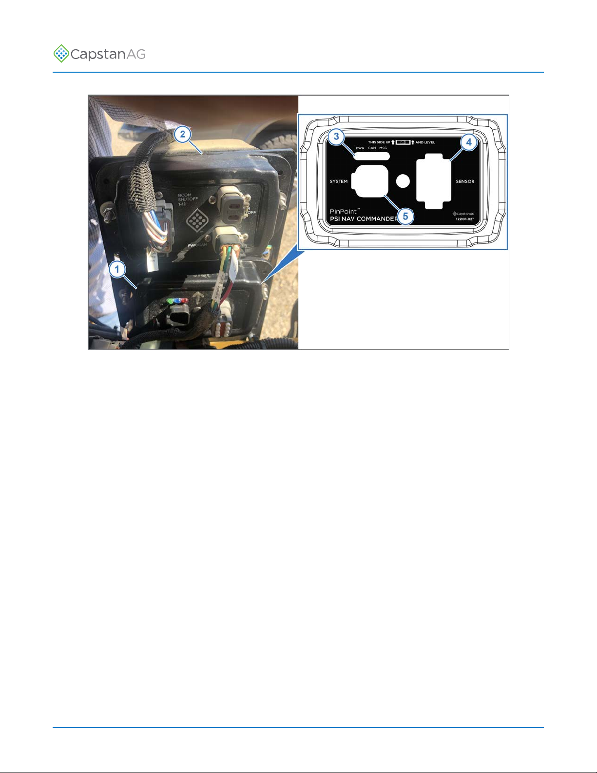
Fig. 2:
2. Install the PSI NAV Commander Module (1) below the SIM Module (2).
The module must be oriented correctly when mounting, with the LEDs (3) at the top of the module.
3. Install the plug into the SENSOR port (4) on the module.
4. Install the end harness into the SYSTEM port (5) on the module.
©2019 Capstan Ag Systems, Inc. 4PSI NAV Commander Module Kit—AGCO
TM
Installation Instructions
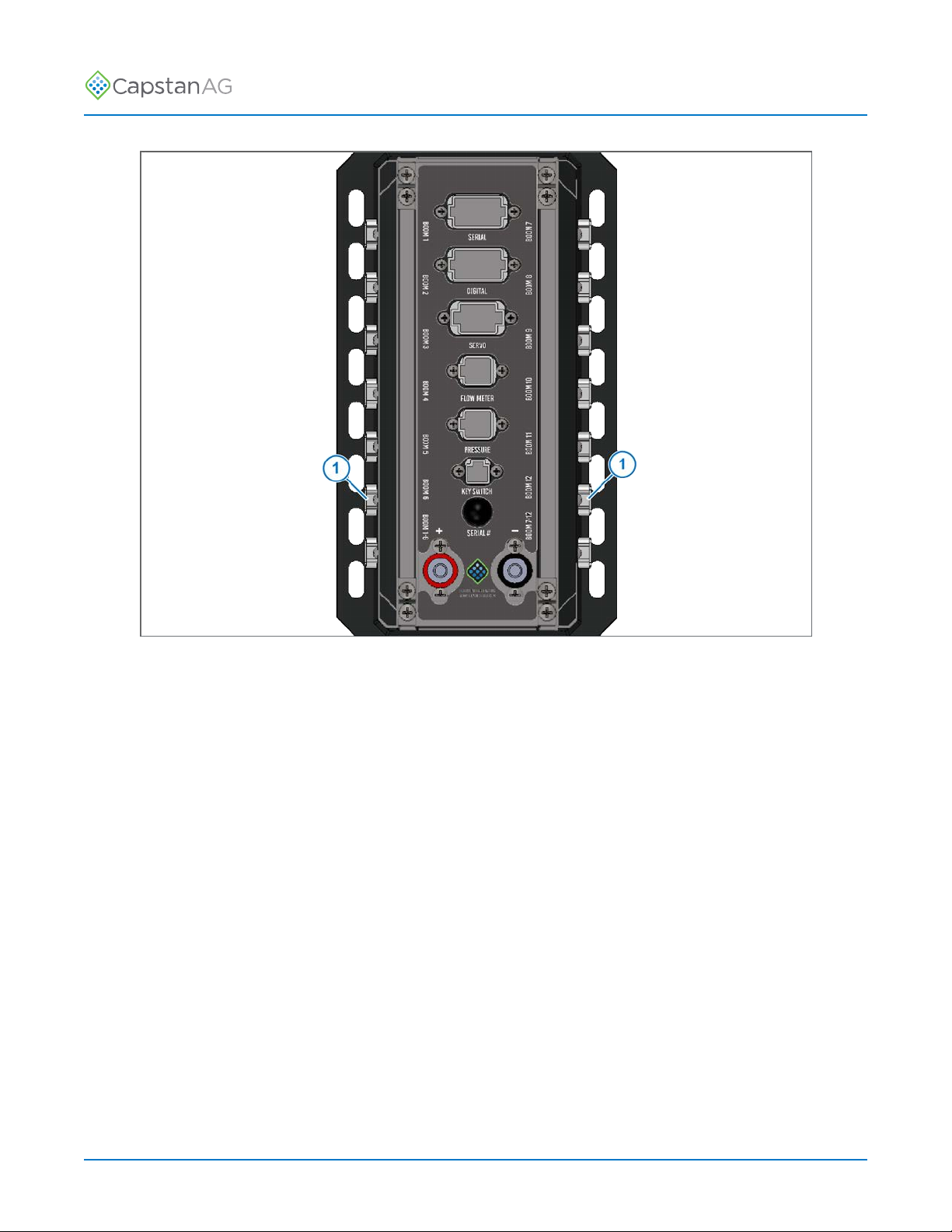
Fig. 3:
5. Route the harness to the Gateway hub.
6. Install the end of the NAV IMU harness with a 6-pin connector and fuse to any open BOOM port
(1) on the Gateway hub.
7. Install the cover onto the Gateway hub.
8. Mount the PSI NAV Commander Module.
©2019 Capstan Ag Systems, Inc. 5PSI NAV Commander Module Kit—AGCO

TM
Installation Instructions
Update PinPoint™II Software
This procedure is for updating PinPoint™II and CapView II display.
Fig. 4:
1. Insert the USB thumb drive (1) into the back of the CapView display (2).
2. The USB Host Menu will show on the screen.
3. Use the up or down arrow to go to the Save Configuration or Save Select Settings line (3).
Use Save Configuration if you are saving the information for the same sprayer and have not
made significant system changes, like changing the number of VCMs.
For software released October 2018 and after, use Save Select Settings if you are saving
information to use on a different sprayer or have made significant system changes, like changing
the number of VCMs.
4. Press the ENTER button (4).
A message screen will show on the display.
5. Use the left or right arrow button (5) to select YES.
6. Press the ENTER button.
The CapView display will show the USB Host Menu.
7. Go to the Upload CapView SW: line (6).
Important: CapView software must be updated first.
On the list, on the upload software lines, there are two software versions that show. The software
version on the left is the version that is currently on your hardware. The software on the right is
the version available on the USB thumb drive. Do not upload the same version of software unless
advised to do so by a CapstanAG representative.
8. Press the ENTER button.
The lights on the display will flash for a few moments, and the CapView display will automatically
power down.
9. Wait five seconds and then press the POWER button (7).
The CapView display will turn on, and a splash screen will show a progress bar advancing across
the screen.
©2019 Capstan Ag Systems, Inc. 6PSI NAV Commander Module Kit—AGCO

TM
Installation Instructions
You do not have to wait until the progress bar disappears before continuing with the procedure.
10.Use the up or down arrow to go to the Upload PowerHub SW: line (8).
11.Press the ENTER button.
12.Upload Gateway Code and a progress bar will show on the screen.
13.When the update process is complete, the USB Host Menu will show.
14.Go to the Upload Software to All VCMs: line (9).
Note: If your system has both 9-channel and 15-channel VCMs you must select the Upload
Software for All VCMs for each version of hardware that is on your system.
15.Press the ENTER button.
16.Upload VCM Code and a progress bar will show.
17.When the update process is complete, the USB Host Menu will show.
18.Remove the USB thumb drive from the back of the CapView display.
19.Press the SYSTEM SETUP button (10).
The first line of the System Setup menu is the Operation Mode line.
20.Make sure that the operation mode is correct:
• Synchro
• SharpShooter
21.Use the up or down arrow to go to the Advanced Settings line.
22.Press the ENTER button.
23.Use the up or down arrow to go to the Factory Reset line.
Note: Make sure that you have saved your configuration before continuing. Do steps 3 to 6 if you
did not previously save configuration.
24.Press the ENTER button.
A message screen will show on the display.
25.Use the left or right arrow button to select YES.
26.Press the ENTER button.
The display will power off.
27.Wait five seconds and then press the POWER button.
A message will show on the CapView display.
28.Press the ENTER button.
29.Insert the USB thumb drive into the back of the CapView.
The USB Host Menu screen will show.
30.Use the up or down arrow to go the Restore Configuration line (11).
31.Press the ENTER button.
A message will show.
32.Use the left or right arrow button to select YES.
33.Press the ENTER button.
The display will power down.
34.Remove the USB thumb drive from the back of the CapView display.
35.Press the POWER button.
36.Press the SYSTEM SETUP button.
37.Make sure that the system shows the correct Operation Mode and that other settings are correct.
©2019 Capstan Ag Systems, Inc. 7PSI NAV Commander Module Kit—AGCO

TM
Installation Instructions
System Setup
Fig. 5:
1. Press the POWER button (1) on the CapView display.
2. Press the SYSTEM SETUP button (2).
3. Use the UP or DOWN arrow buttons (3) to go to the Advanced Settings line.
4. Press the ENTER button (4).
5. Use the UP or DOWN arrow buttons to go to the Navigation IMU line.
6. Press the ENTER button.
7. Make sure that the Navigation IMU line is enabled.
This feature allows for quicker response time for the headings and can be used with or without a
Raven RS1 Antenna.
Important: The PSI NAV Commander Module must be mounted in the correct orientation.
8. Press the ENTER button.
9. Use the UP or DOWN arrow buttons to go to the GPS Lag Time Line.
10.Press the ENTER button.
11.Change the value to help with any GPS issues.
This value corrects any delayed GPS signal from the antenna.
12.Press the ENTER button.
13.Use the UP or DOWN arrow buttons to go to the Compass Heading line.
14.Press the ENTER button.
15.Select Yes to proceed with a compass calibration.
16.Follow the directions on the screen to do the compass calibration procedure.
17.Press the ENTER button.
18.Press the ESCAPE/MAP button (5) twice to go to the main screen.
You should be ready to operate the machine.
©2019 Capstan Ag Systems, Inc. 8PSI NAV Commander Module Kit—AGCO
Table of contents
Popular Control Unit manuals by other brands

Festo
Festo Compact Performance CP-FB6-E Brief description

Elo TouchSystems
Elo TouchSystems DMS-SA19P-EXTME Quick installation guide

JS Automation
JS Automation MPC3034A user manual

JAUDT
JAUDT SW GII 6406 Series Translation of the original operating instructions

Spektrum
Spektrum Air Module System manual

BOC Edwards
BOC Edwards Q Series instruction manual

KHADAS
KHADAS BT Magic quick start

Etherma
Etherma eNEXHO-IL Assembly and operating instructions

PMFoundations
PMFoundations Attenuverter Assembly guide

GEA
GEA VARIVENT Operating instruction

Walther Systemtechnik
Walther Systemtechnik VMS-05 Assembly instructions

Altronix
Altronix LINQ8PD Installation and programming manual


