Thetford Mk12 HOTPLATE Operating instructions

PCC 1277Z– Issue 11
USER AND INSTALLATION INSTRUCTIONS
WARNING
•This appliance must be installed by an authorised person.
•Only use this appliance in a well ventilated area.
•Read the instructions before use.
THETFORD AUSTRALIA PTY LTD
41 LARA WAY CAMPBELLFIELD VIC
TEL: 03 9358 0700 FAX: 03 9357 7060
FOR USE IN AUSTRALIA
Mk12 HOTPLATE
2 BURNER & GRILL
FOR USE WITH UNIVERSAL LPG

2
•This appliance is designed for Universal LPG and should not be converted
for use with any other gas.
•Use only the gas pressure specified.
•Do not modify this appliance

3
Model: S~HT27648Z
OFF FULL RATE LOW RATE
1/4in BSP Tapered Female Gas Connection

4
INTRODUCTION
In your own interest of safety, gas appliances should be installed by competent persons.
Failure to install the appliance correctly could invalidate any warranty or liability claims.
This appliance shall be installed in accordance with the manufacturer’s installation
instructions, local gas fitting regulations, municipal building codes, AS/NZS5601 and any
other relevant statutory regulations.
Data Label
The data label is located on the rear panel of the hotplate. A duplicate data label is
supplied to adhere to an accessible area next to the appliance. Ensure that the gas supply
is UNIVERSAL LPG. This appliance is designed for use with Universal LPG and should
not be converted for use with any other gas.
Ventilation
Ventilation must be in accordance with AS/NZS5601 Installation Code. In general, the
appliance should have adequate ventilation for complete combustion of gas, proper flueing
and to maintain temperature of immediate surroundings within safe limits. When used
outdoors, it is recommended that a metal windshield be used.
Location
Choose a location free of draughts, open doors and clear of combustible materials or other
fire hazards. The location should ensure convenience of operation and service. Any
adjoining wall surface situated within 200mm from the edge of any hob burner must be a
suitable non-combustible material for a height of 150mm for the entire length of the
hotplate.
Any combustible construction above the hotplate must be at least 600mm above the top of
the burner and no construction shall be within 450mm above the top of the burner.
The surface that the hotplate sits on should be protected by a layer of non-combustible
material to prevent damage by the heat from the grill.
INSTALLATION
This is a cooking appliance for use in a camping environment and must be used on a firm
and stable structure in compliance with the location requirements above.
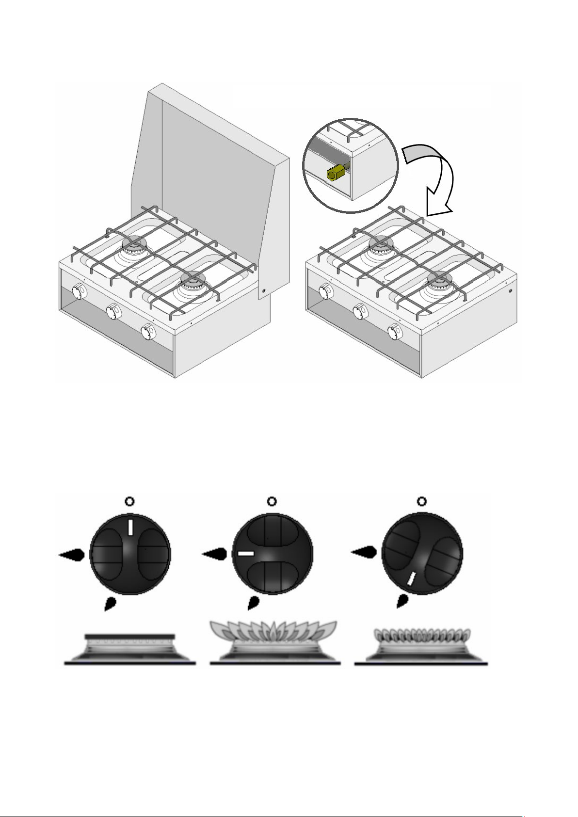
Gas Connection
A ¼” (BSP) female gas connection is provided on the back of the appliance. Refer to the
diagrams for location of the gas inlet. It is recommended that the appliance be connected
by copper tubing. For use outdoors a hose assembly complying with AS/NZ1869 may be
used. Care should be taken to ensure the hose is not exposed to temperatures exceeding
that for which it is certified and is not subjected to abrasion, kinking or deformation. After
connection the appliance must be tested for soundness.
This appliance is suitable for use with; Universal LPG Only 2.75 Kpa.
It is important that the regulator should be set to the correct pressure for the type of gas
being used. Excessive pressure must not be permitted.

5
INSTALLATION
If the flame on either the top burners or the grill show a tendency to lift, it is probable that
the line pressure is too great. Should there be excessive yellow tips (resulting in sooting)
then it is probable that the line pressure is too low and, in either case, the burners should
not be used until the line pressure has been checked.
The burners on this appliance have fixed aeration and no adjustment is necessary.
When satisfied with the appliance, please instruct the user on the correct method of
operation. If the appliance fails to operate correctly after all checks have been made, refer
to the authorised service provider in your area.
MAINTENANCE
We recommend an annual service by an authorised service agent to maintain efficient
appliance performance. In between annual service the appliance needs little maintenance
other than cleaning. All parts should be cleaned using warm soapy water. Do not use
abrasive cleaners, steel wool or cleansing powders. When cleaning the burner ring it is
essential to ensure that the holes do not become blocked.
The control knobs are a push fit and can be removed for cleaning. They are
interchangeable without affecting the sense of operation.
Any of the following are considered to be abnormal operation and may require servicing.
•Yellow flames (Slight yellow tipping is normal).
•Sooting of cooking utensils.
•Burners not igniting properly.
•Burners failing to remain alight
•Burners extinguished by cupboard doors.
•Gas valves that are difficult to turn
•After installation the appliance MUST be tested for soundness
•Test ALL burners on high and low flame for flame stability.
•The gas supply input pressure MUST not rise or fall significantly from
nominal when ALL appliances connected to the supply are operated
simultaneously.
•If NOT installed to the manufacturers instructions detailed herein, we the
manufacturer can not be held responsible for any problems that occur, or
poor performance that is perceived/witnessed.

6
OPERATION
Using the Hob Burners
Each burner is controlled individually and is monitored by a flame failure sensing device.
The respective knob positions for Full Rate, Low rate and Off are shown on page 3.
1. Ensure gas supply is connected and turned on.
2. To light: Push in the control knob and turn anti-clockwise to full rate – large flame on
control knob () Fig. 1.
3. Continue holding the knob depressed whilst holding a lighted match or taper to the
burner. For models fitted with Spark Ignition the procedure is similar except that the
burner can be ignited by depressing the ignition button located on the fascia.
4. After the burner is lit continue depressing the knob for approximately 10 - 15
seconds before release.
5. If burner has not lit within 15 seconds, release knob and wait at least 1 minute
before repeating operations (2) to (4).
6. If required the knob can be turned further anti-clockwise to the simmer position. To
turn off, rotate the control knob anti-clockwise until the circle on the knob is aligned
with the dot on the fascia panel
Using the Grill
Control of the grill burner is identical to that used for the hob burners. Although the grill
does heat up quickly, it is recommended that a few minutes preheat be allowed. The grill
pan should be left in position to protect the base lining.
A reversible grill pan trivet enables the correct grilling height to be achieved.
•DO NOT USE OR STORE FLAMMABLE MATERIALS IN OR NEAR THE
APPLIANCE.
•DO NOT SPRAY AEROSOLS IN THE VICINITY OF THIS APPLIANCE
WHILE IT IS IN OPERATION.
•WHERE THIS APPLIANCE IS INSTALLED IN MARINE CRAFT OR IN
CARAVANS, IT SHALL NOT BE USED AS A SPACE HEATER.
•IF FITTED IN A CARAVAN OR MOTOR VAN, ALL BURNERS SHOULD BE
EXTINGUISHED WHEN THE VEHICLE IN WHICH THE APPLIANCE IS
INSTALLED IS MOVING. IT IS RECOMMENDED THE CYLINDER VALVE
TO THE APPLIANCE BE TURNED OFF.
•When cooking keep children away from the vicinity. Turn pan handles
inwards so they cannot be caught accidentally.
•On models fitted with a fold down lid, never operate the appliance with the
lid in the closed position.
•Never leave fat or oil unattended on the hotplate.
•When finished, check that all controls are in the off position.

7
OPERATION
LEAKS
If a smell of gas becomes apparent, the supply should be turned off at the cylinder
IMMEDIATELY.
•Extinguish naked lights including cigarettes and pipes.
•Do not operate electrical switches.
•Open all doors and windows to disperse any gas escape.
•Universal LPG is heavier than air; any gas escaping will therefore collect at low
level. The strong unpleasant smell of gas will enable the general area of the leak to
be detected. Check that the gas is not escaping from an unlit appliance.
•Never check for leaks with a naked flame, leak investigation should be carried out
using a leak detector spray.
SERVICING
ALL SERVICING MUST BE CARRIED OUT BY AN AUTHORISED PERSON
A pressure test point is fitted to the gas manifold located below the control panel. The
pressure is measured with the front left burner on high flame and with an inlet pressure of
2.75 kPa (Universal LPG).
For service, please contact your authorised local Service Agent giving full details of the
model, serial number and date of purchase.
MANUFACTURED BY:
THETFORD Ltd.
Unit 6 Brookfields Way, Manvers
Rotherham S63 5DL. England.
1. Hob Burner Injector removal/replacement
•Remove the pan support by pulling up to release it from the spring clips.
•Remove the appropriate burner cap and skirt.
•With a 7mm A/F socket, unscrew injector from the bottom of the burner mixing tube.
•Replace/refit using the reverse procedure.
2. Thermocouple removal/replacement
•Shut off gas supply and disconnect gas supply pipe from the unit.
•Remove the spring clip retaining the thermocouple at the burner.
•From the underside of the hob, remove the appropriate thermocouple from the gas
valve and detach both connections to the shut off switch attached to the hinge
•Remove the thermocouple.
•Replace/refit using reverse procedure
•DO NOT MODIFY THIS APPLIANCE.
•NO PARTS OTHER THAN THOSE SUPPLIED BY THE MANUFACTURER
SHOULD BE USED ON THIS APPLIANCE.
This manual suits for next models
1
Table of contents
Other Thetford Cooktop manuals
Popular Cooktop manuals by other brands

KitchenAid
KitchenAid KICU500XSS installation instructions

Whirlpool
Whirlpool SC8720EDB installation instructions

GE
GE Profile PP945SMSS Dimensions and installation information

SIMPA
SIMPA WZH13K user manual

Miele
Miele HR 1124 Operating instrucitons

Sterling
Sterling BGH 1 Installation & user's instructions