Thiel SmartSub SS2 Manual

Technical Information
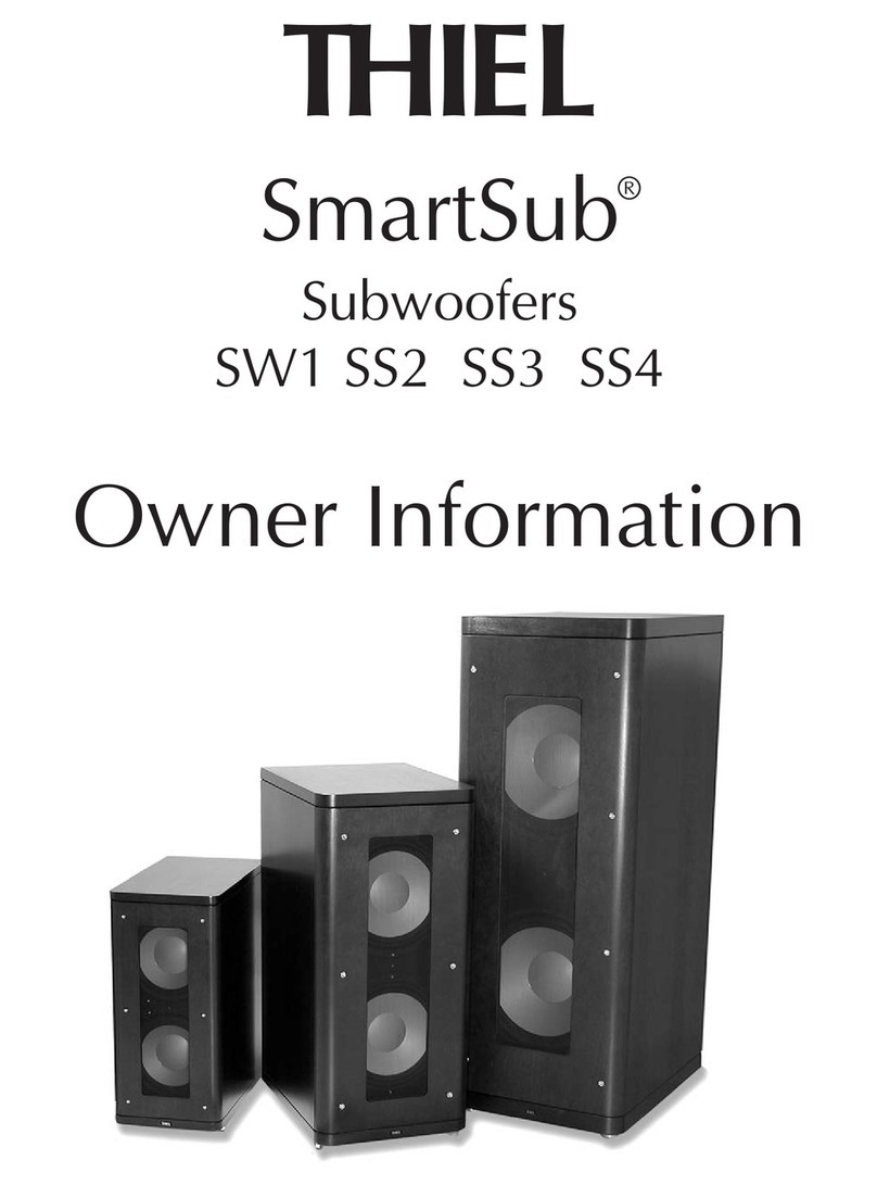
THIEL
SmartSub
Subwoofers
®

2
THE GOAL
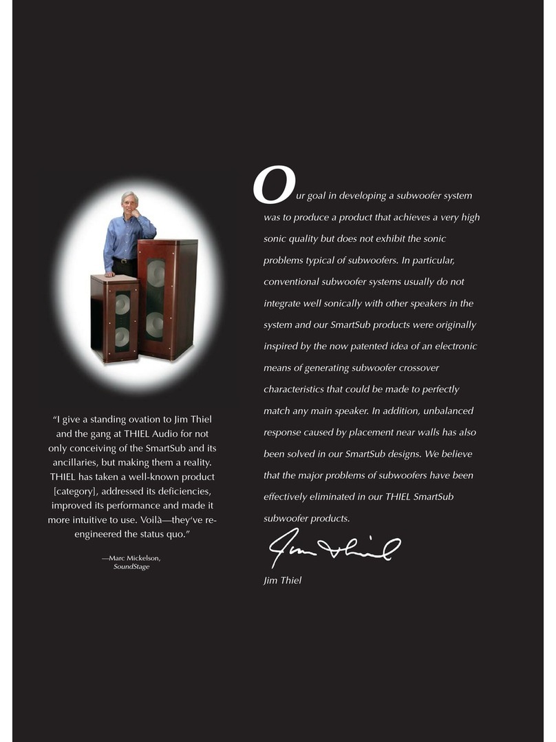
Our goal in developing a subwoofer system was to
produce a product that achieved very high sonic quality and
that did not exhibit the sonic problems typical of subwoofers.
In particular, subwoofer systems usually do not integrate
well sonically with the other speakers in the system and this
product was originally inspired by the conception of an
electronic means of generating subwoofer low-pass
crossover characteristics that could be made to perfectly
Most subwoofer crossovers attempt (or merely profess) to
deal with the unknown variables of the main speaker’s
response by providing additional controls, including phase,
polarity, and separately adjustable low- and high-pass
frequency. While it is possible that in some cases good
results can be obtained by use of these controls, in most
cases it is still not possible to achieve the desired blending
and integration of the subwoofer and the main speakers. And
even in cases where good results can be obtained, there is no
way to know how the controls should be set to achieve
optimum performance since the required settings are not
usually those that would seem logical.
We needed a completely different approach to
subwoofer crossovers that was able to take into account the
response of the main speakers in order to provide crossover
performance that achieves desired results with simple and
logical control settings. The conception of the technical
means to achieve such performance was the original impetus
for the THIEL SmartSub development.
Room effects
The effects of the third category of problem are well
known. Almost every subwoofer installation is plagued by
response irregularities that are habitually attributed to “room
resonances”. A study of the situation reveals that the majority
of serious problems are not, in fact, and strictly speaking,
room resonance problems, but rather, boundary problems of
cancellation and reinforcement. Even though the effects on
performance are similar, the distinction is important because
it indicates a quite different type of solution. Room
resonance problems cannot really be solved by any method
other than physically changing the proportions and size of
the room. Further, even mitigating the effects with equalizers
can only be accomplished for one listener location, with the
usual result of worsening the problems for other locations.
In constrast, boundary problems are fundamentally and
importantly different. Boundary effects are substantially
consistent throughout the room and therefore corrections are
improvements for all locations. Also, the effects of nearby
boundaries are predictable and therefore can be corrected
without measurements. Such a built-in system of boundary
compensation is an important aspect of the THIEL SmartSub
system.
match any main speaker. Further impetus was added to the
project by the realization that the placement problems of
altered and unbalanced response caused by nearby walls
could also be solved.
We believe that the major problems of subwoofers have
been effectively eliminated in the SmartSub subwoofers and
the following details the highlights of their performance
features.
THE PROBLEMS
Subwoofer performance problems can be categorized
into 3 types:
1) Output/distortion/uniformity problems.
2) Problems of sonic integration with the main speakers.
3) Room interaction problems.
Examples of the first type are thumpy, dirty and strained
low frequencies; of the second disjointed sound character,
misbalanced levels and seemingly disconnected low
frequencies; of the third are subjectively overly dominant or
“missing” tones and sonic balance and character that change
with different subwoofer placement.
Low Frequency performance
It is difficult and expensive to reproduce deep bass at
high loudness levels with the low distortion that can be
achieved by high quality speakers at higher frequencies and/
or lower loudness levels. Therefore, many subwoofers do not
attempt to reproduce truly deep bass but rather are designed
to accept very high input levels of bass energy without
obvious distress. Often this characteristic is achieved by
restricting reproduction of deep bass and by incorporating
severe compression of the signal so that demanding inputs do
not overtax woofers and amplifiers of modest ability.
These limitations of most subwoofers can be overcome
with normal engineering. However, such performance
requires very high output drivers and a large amount of
power, neither of which can be obtained at low cost. And
even when a product is engineered to provide a truly high
level of low frequency performance, this does not solve the
two other categories of problems subwoofers exhibit.
Integration
The second category of problem is the result of the fact
that the crossovers typically employed are generic types and
that they do not take into account the low frequency
characteristics of the main speakers. This is true whether the
crossover used is the bass management capability of the
processor or the built-in crossover included with most
subwoofers. Usually these crossovers will provide the
desired blending only for the theoretical case of the main
speakers and the subwoofer both having low frequency
response flat down to DC. Since this is never true, the results
obtained are off a little or a lot, depending on other variables.

SMARTSUB
The most noteworthy features and benefits of the THIEL
SmartSubs can be listed in four categories. These topics are
the subject of this paper.
• The ability to achieve a near-perfect, seamless
transition with any main speakers when used to reproduce
the bass range of channels other than LFE, in video or music
systems. (Patents pending)
• The quality of bass reproduction; low distortion and
very high output.
• The ability to accurately correct the problems of
reinforcement and cancellations caused by nearby walls and
corners. (Patent pending)
• The ability to correct lowered sensitivity and response
changes that are otherwise caused by heating of the drivers’
voice coils so that the response remains correct and
uncompressed during high demand. (Patent pending)
The first of the above mentioned benefits is
implemented with the separate companion crossover unit, the
SmartSub Integrator, that can be used to process 2 channels
of information and deliver a signal to multiple subwoofer
units. The other three of these benefits of the SmartSub
system are implemented in the subwoofer unit.
OUTPUT ABILITY
The ability to play deep bass loudly is a function
of how much air the drivers can move without
excessive distortion, which in turn is dependent on
both the size of the diaphragms and their linear
excursion. It is important to realize that simply
possessing a large mechanical excursion is not
beneficial if the magnetic excursion is not also large. If
the cone can move 1" but the coil comes out of the
magnetic gap, the distortion will be very high.
The SmartSubs include two very high
excursion drivers with a linear excursion
capability so large (1-1/4" pk-pk) that each driver
can move considerably more air than most
drivers their size.
The specially designed suspension allows
a linear mechanical excursion of more than 2"
pk-pk so that it does not contribute to non-
linearity and distortion.
The SS2, SS3 and SS4 are internally
powered with a 1000 watt rms switching mode
amplifier to realize the full output ability of the
drivers. This type of amplifier provides the
benefit of high efficiency, about 92% in this case,
which allows smaller heat sinks and power
supplies. The sonic quality of this type of amplifier
has improved greatly in recent years, to the point
where they can provide high sound quality even in
full range applications. They are very good for
3
The 1000 watt switching amplifier used in the SS2, SS3 and SS4. This amp includes
electronic compensation for room boundary and thermal driver effects.
The Integrator is used if the subwoofer is required to
reproduce the bass energy in channels other than the LFE
channel, for example, in the left/right channels. Such a
configuration is desirable if the main speakers either cannot
reproduce the full range of bass or if they cannot play at
sufficient sound levels without bass distortion.
The Integrator does not have traditional controls for
directly controlling crossover characteristics such as slope or
phase for either the subwoofer or the main speaker high pass
filters. Instead, a different approach is taken. There are
settings for telling the Integrator the characteristics of the
main speakers being matched, if a main speaker high-pass is
desired (crossover mode) or not (augment mode), and what
crossover frequency is desired. With this information the
Integrator calculates what filter characteristics will provide
seamless integration of the sub with the main speakers.
The Integrator has speaker level inputs for use in
augment mode and both balanced and unbalanced line level
inputs and outputs for use in crossover mode. Signal is
supplied to the subwoofer via balanced line level
connections.
All signal processing is done with analog circuitry.
Digital circuitry is used for user interface, calculation and
circuit control functions.
powered subwoofer applications because they can develop a
large amount of power with very little heat and because any
residual "digital" distortions occur at high frequencies which
are unused in subwoofer applications.

long coil
short
magnetic
gap
DISTORTION
The SmartSub drivers incorporate several unusual
design features, utilized in all THIEL woofers, that greatly
reduce distortion compared with conventional designs. Here
is a brief explanation of three of these.
The purpose of the driver’s motor system is to apply a
force to the diaphragm that is directly proportional to the
voltage supplied by the amplifier. In order for the force to be
directly proportional to the voltage applied, as desired, three
conditions must be met:
• the length of voice coil wire acted on by the magnetic
field must be constant,
• the magnetic field strength must be constant,
• and the current in the voice coil must be directly
proportional to the applied voltage.
In practice, none of these conditions actually exist and
inaccuracy in each is a distortion mechanism. All THIEL
drivers incorporate refinements of design that greatly
improve the accuracy of each of these three factors.
The first distortion mechanism results from the fact that
almost all drivers use a long coil/short gap motor system
where the long coil is acted upon not only by the field within
the magnetic gap but also by the “fringe” field in front of
and behind the gap region. As the coil moves forward or
backward to produce bass energy, the magnetic field acting
on the coil becomes less intense because the coil is farther
from its rest position where the magnetic field is strongest.
This weakening of field strength as the coil moves away
from its rest position is usually the primary distortion
producing mechanism.
The following graph is the magnetic flux density vs.
distance from the center of the gap for a normal, short gap
magnet system. You can see that the field in the gap (darker
region) is less than half of the total field acting on the coil
(all shaded regions) and that the field in the overhung
regions (light grey) is not constant with distance from the
gap. This produces distortion during movement.
To eliminate this problem all THIEL drivers use an
unusual short coil/long gap system where the coil is much
Conventional long coil/ short gap motor system
0
mm from center of magnetic gap
Magnetic flux density
Gap length
Coil length
0
-10
-20-30 30
10 20
shorter than the magnetic gap. Therefore, even when the coil
moves a considerable distance from its rest position, it
continues to be acted upon only by the uniform magnetic
field in the air gap and does not experience the changes in
magnetic field strength with position as in the conventional
system. The distortion produced by short coil motor system
woofers at normal excursion levels is typically only one-
0
0-10
-20-30 30
10 20
mm from center of magnetic gap
Magnetic flux density
Gap length
Coil length
SmartSub short coil/ long gap motor system
4
tenth that produced by normal long coil system. The penalty
of this approach is that a much larger magnet is needed to
power the much longer gap.
In the next graph you can see that as the coil (dark
region) moves through the gap (light region) the magnetic
field remains constant, greatly reducing distortion produced
by this mechanism.
copper pole slee
v
copper ring
short coil
very large
magnet
aluminum diaphragm

5
The next graph shows the distortion produced by each of
these systems. In both cases the Xmax value is 15 mm,
meaning the coil should be able to move 15 mm each way
without excessive distortion. You can see that the normal
system produces 17% distortion at this excursion whereas
the long gap system produces less than 2% — only one-tenth
as much! Also, at the slightly more normal excursion of 12
mm, the normal system produces 10% distortion whereas the
short coil system produces less than 0.5%— a twenty fold
improvement.
The second distortion mechanism is that the strength of
the magnet’s field is not actually constant in operation but is
changed by the current from the amplifier through the coil.
This change occurs because the amplifier current through the
coil generates the force to move the diaphragm by creating
its own magnetic field that “pushes” against the magnet’s
field. The magnet is somewhat demagnetized by the coil’s
magnetic field when current flows in one direction and is
remagnetized when current flows in the opposite direction.
Therefore, since the magnet’s field strength is not constant,
the force generated is not in the desired direct proportion to
the current in the coil.
To greatly reduce this effect the SS2 drivers incorporate
a thick copper ring around the center pole. With this ring any
0
5
10
15
20
0246810121416
Xmax = 15 mm in both cases
Long coil / short gap
Short coil / long gap
Peak excursion — ±mm
THD — %
Copper pole sleeve and ring used in the SS2 woofers to stabilize the magnetic field strength
for reduced distortion.
changes in the magnet’s strength induces an electrical current
in the ring which generates a magnetic field that is opposed
to and practically cancels the original change.
The third distortion mechanism is that the voice coil
current is dependent not only on the driving voltage and the
coil resistance but also on the voice coil inductance. The
problem is that the coil inductance varies with the amount of
iron inside the coil and, therefore, with conventional magnet
system geometry, the inductance changes during the
excursions necessary to reproduce low frequencies. As the
diaphragm and coil move back, more of the coil is around
the pole, increasing the inductance and decreasing the mid-
frequency output of the driver. As the coil moves forward,
less of the coil is around the pole, the inductance decreases,
and the higher frequency response increases. By this
mechanism the frequency response of the speaker is
modulated by driver excursion. This problem has been
practically eliminated in all THIEL drivers. The short coil
design results in the entire coil surrounding the pole in all
positions and therefore the coil’s inductance does not change
with the diaphragm position. In addition, the problem is
further reduced by a copper pole sleeve which reduces the
inductance of the coil to a fraction of its normal value by
acting as a shorted turn of a transformer secondary winding.
An additional problem is that the coil is an iron-core
inductor. Since iron is not magnetically linear, the coil’s
inductance changes with current in the coil and for this
reason such inductors are avoided in high quality crossover
systems. An additional benefit of the copper sleeve is that
since it reduces the coil’s inductance it also reduces the
distortion associated with changing inductance.
One of two SS2 drivers

Thermal Compression
Subwoofers achieve deep bass response even though
their enclosures are usually quite small in proportion to the
driver cone area because they are equalized. Without
equalization the response might extend only to 50 Hz or 40
Hz. The lowest frequencies are boosted to provide balanced
system response to low frequencies. A consequence of this
boosting is that much more power is delivered to the driver
than in a normal, unequalized speaker. The power supplied to
the drivers at 20 Hz can be 20 or more times normal. This
large amount of power results in the coils running hot even
during only moderately high demands.
A significant problem stems from the fact that the
electrical resistance of copper is strongly temperature
dependent, having a temperature coefficient of 0.39%/°C.
Therefore, when the voice coil temperature reaches 200°C,
the resistance has increased by 70% which causes a
reduction in current, and, therefore, output, by 4.5 dB.
The situation is actually more complicated because
resistance is only one of three components of driver
impedance (although the largest at most subwoofer
frequencies), the others being motional and inductive
impedance. The following graph shows the total impedance
of the drivers in the enclosure and also the resistive, motional
and inductive components that combine to produce it.
Frequency
Amplitude - dB
-25
-15
-5
5
15
110100 100
0
Frequency
Amplitude - dB
-25
-15
-5
5
15
110100 100
0
Total impedance of the SS2 (top line) and its components of resistance (at 0 dB), motional
impedance and inductance.
Top to bottom: total impedance at 200°C, at room temperature, and the sensitivity
change at the elevated temperature.
6
Since the resistance is the only one of these three
impedance components that is temperature dependent, the
impedance does not increase with temperature uniformly at
all frequencies. Where the other components are major
contributors to the total impedance, near resonance and at
higher frequencies, the impedance does not increase as much
as it does at other frequencies. Therefore, the shape of the
total impedance curve changes and therefore the frequency
response changes. The following graph illustrates, from top
to bottom, the impedance at 200°C, the room temperature
impedance, and the change in frequency response that
results. You can see that the sensitivity has decreased 2.5 dB
at 40 Hz but 4 dB at 20 and 80 Hz.
A Solution
The SmartSub incorporates a solution that consists of
measuring voice coil temperature in real time and using
this information to adjust the gain and frequency response
of the amplifier to correct the sensitivity and response
changes that would otherwise occur. This correction
ensures that the output is not compressed or imbalanced
during high demand.
Heat sensor on voice coil

Wall and Corner Placement Problems
It is well known that placing any speaker, including a
subwoofer, near a wall will cause both an increase in bass
level and unevenness in the response due to reflection from
the wall. The effects of corner placement are more complex
than single-wall placement since there are then two sets of
low frequency level and reflection effects. In fact, these
effects are quite predictable.
The general increase in level affects frequencies below
approximately 300 Hz and its degree is dependent on the
distance from the wall. It is caused by the fact that the sound
radiation is confined to a smaller and smaller solid angle as
the speaker’s distance to the wall becomes less and less. This
effect is illustrated in this graph for wall distances of 1.8, 1.0
and 0.5 meters.
The reflection from the wall causes a partial cancellation
in a particular frequency range which is determined by the
distance to the wall. The severity of the cancellation is
determined by the strength of the reflection which is also
determined by the speaker-to-wall distance. So, if the speaker
is a relatively large distance from the wall, the cancellation
will occur at a low frequency and be mild. If the speaker is
close to the wall the effect occurs at a higher frequency range
and is more severe. This second graph illustrates the wall
reflection effect for the same three distances. When both
these effects are added together, the result is illustrated in the
third graph.
7
Frequency
Amplitude - dB
-10
0
10
10 100 10
0
Response changes caused by both reinforcement and reflection from a nearby wall at
distances of 1.8, 1 and 0.5 meters.
Frequency
Amplitude - dB
-10
0
10
10 100 10
0
Response changes caused by reflection from a nearby wall at distances of 1.8, 1 and 0.5
meters.
Frequency
Amplitude - dB
-10
0
10
10 100 10
0
Response changes caused by reinforcement from a nearby wall at distances of 1.8, 1 and
0.5 meters.
Frequency
Amplitude - dB
-10
0
10
10 100 10
0
Response change caused by near-corner placement of one-half meter from side wall and
1.2 meters from rear wall.
Frequency
Amplitude - dB
-10
0
10
10 100 10
0
Correction supplied for a side wall distance of one-half meter and a rear wall distance of 1.2
meters.
Since all three variables of the boundary effect (degree
of reinforcement, cancellation frequency and cancellation
severity) are determined solely by the wall distance, they can
be accurately compensated for if the wall distance is known.
All SmartSubs incorporate placement compensation
whereby one control setting, calibrated in distance from the
wall, corrects reinforcement, cancellation amount and
cancellation frequency. By incorporating two sets of wall
compensation which are independently adjustable, the
SmartSubs are able to accurately compensate for virtually
any placement.
For example, the fourth graph illustrates the effect of
placing a speaker 0.5 and 1.2 meters from a corner. The
inverse compensation supplied by the SmartSub for this
placement is illustrated in the last graph.

Integration problems
If the subwoofer is to reproduce the bass range of the
main channels, in addition to the subwoofer channel, there
are major potential problems with the crossover between the
subwoofer and the main speakers.
There are two possible ways a subwoofer can be used to
reproduce main channel bass: augment or crossover.
Augment operation allows the main speakers to operate
normally, without a crossover, and the subwoofer is used
“fill-in” the deep bass below the range of the main speaker.
Crossover mode transfers some of the bass range from the
main speakers to the subwoofer. Each of these types of use
can be used with two types of main loudspeakers, sealed or
reflex. Following are examples illustrating typical results for
each case.
It is assumed that the subwoofer crossover configuration
is what I consider optimum for generic filters. The sub low
pass (LP) filter is 4th order, Q=.5, the main speaker high
pass (HP) filter is 2nd order, Q=.7, the HP frequency tracks
the LP frequency, and there is also a continuously variable
phase control.
The simplest case is to use crossover with sealed main
speakers. In the special case where the crossover frequency
is set to the speaker’s limit (-3 dB) frequency, the crossover’s
HP will combine with the speaker’s bass response to achieve
a total 4th order, Q=.5 hi pass response that will, in theory,
perfectly cross over with the 4th order, Q=.5 sub low pass
response. However, in practice, even this simple case is upset
by the complication that the sub’s response does not extend
to DC. For an 80 Hz crossover, if the sub has a 4th order
rolloff at 35 Hz, the interactive phase effects will cause the
whole bass range to be 2 dB weak (Fig. 1).
Increasing the signal level to the sub solves this
problem, but the system response still suffers from excessive
output in the 100 - 200 Hz region.
In the more general case where the crossover frequency
is higher than the main speaker’s frequency, the results are
not as good. For example, if the main speaker’s response
extends to 50 Hz and the crossover is at 80 Hz, the bass
response is 4 dB weak (Fig. 2). Even when the phase and
level are adjusted to be optimum (180°, -1 dB) the response
is not nearly ideal (Fig. 3).
In cases where the main speakers are ported, things are
no better. For example, if the main speakers are tuned to 50
Hz and you want to implement an 80 Hz crossover with the
sub extending to 25 Hz, the results achieved without phase
adjustment are not what is desired. Even when the phase
control is set optimally (80°@ 50 Hz) the results are not
good, giving a hump in the bass while still giving weak
upper bass (Fig. 4).
Fig. 1 Subwoofer extending to 35 Hz and crossing-over at 80 Hz with a sealed, 80 Hz main
speaker. Standard settings.
Fig. 2 Subwoofer extending to 35 Hz and crossing-over at 80 Hz with a sealed, 50 Hz main
speaker. Standard settings.
Fig. 3 Subwoofer extending to 35 Hz and crossing-over at 80 Hz with a sealed, 50 Hz main
speaker. Optimum phase and level adjustment.
Fig. 4 Subwoofer extending to 25 Hz and crossing-over at 80 Hz with a reflex, 50 Hz main
speaker. Optimum phase and level adjustment.
8
-15
-10
-5
0
5
10 100 1000
Frequency
Amplitude - dB
-15
-10
-5
0
5
10 100 1000
Frequency
Amplitude - dB
-15
-10
-5
0
5
10 100 1000
Frequency
Amplitude - dB
-15
-10
-5
0
5
10 100 1000
Frequency
Amplitude - dB

If you want the sub to augment the main speakers,
without adding a high pass into their response, the results are
usually even less desirable. If the main speaker is a reflex
type at 50 Hz and the sub extends to 30 Hz, the bass is very
weak without a phase adjustment (Fig. 5); the polarity must
be reversed to get good results.
In the case of augmenting a sealed system, it is usually
not possible to obtain good results. For example, a 50 Hz
speaker will produce a severe null at the crossover frequency
without a phase adjustment (Fig. 6). Even with optimum
phase and level, the results are an exaggerated mid bass and
a lack of deep bass (Fig. 7).
Fig. 5 Subwoofer (attempted) extending to 30 Hz augmenting a 50 Hz reflex main speaker.
No phase adjustment.
Fig. 7 Subwoofer (attempted) extending to 30 Hz augmenting a 50 Hz sealed main speaker.
Optimum phase adjustment.
Fig. 6 Subwoofer augmenting to 30 Hz a 50 Hz a sealed speaker. No phase adjustment.
9
These examples illustrate the typical problems inherent
in matching a subwoofer to other speakers:
• “Logical” settings do not give the desired results
• It is not known which level and phase control settings
will give optimum results. They must be adjusted without
rhyme or reason by trail and error
• Optimum results are usually not very good.
-15
-10
-5
0
5
10 100 1000
Frequency
Amplitude - dB
-15
-10
-5
0
5
10 100 1000
Frequency
Amplitude - dB
-15
-10
-5
0
5
10 100 1000
Frequency
Amplitude - dB

-15
-10
-5
0
5
10 100 1000
Frequency
Amplitude – dB
Another example illustrates this “custom” slope ability
of the crossover unit. If the sub is augmenting a sealed 60 Hz
speaker, the crossover again provides the output that will
produce exactly the desired combined output (Fig. 9). Again,
the dotted line shows what a generic filter would provide
and, in this case, the difference is large. The proper curve
provides more output below 25 Hz and less above, with a
slightly more gentle slope.
The following example illustrates the second technique
of providing a special HP response that will combine with
the speaker’s response so that the total response is correct. If
an 80 Hz crossover is desired with a 60 Hz sealed main
speaker, the HP supplied by the SmartSub crossover is an
unusual shape that resembles an 80 Hz 4th order above 60
Hz and a 2nd order below (Fig. 10).
If the same crossover is desired with a 60 Hz reflex
speaker, you can see in Fig. 11 that the supplied HP shelves
below 60 Hz so that, again, the response of the filter
combined with that of the speaker will have the desired 80
Hz, 4th order characteristics.
A solution
Our desire was to take the guesswork out of subwoofer
crossover adjustments and to be able to easily achieve
accurate results with any main speaker. The approach we
have taken to achieve this goal is different from all others.
Rather than telling the subwoofer how to perform by using
controls for crossover frequency, level and phase, the THIEL
subwoofer crossover unit has settings for the characteristics
of the main speakers you are matching, the configuration of
your system and the performance you desire. This
information is then used to calculate and provide the ideal
subwoofer response and hi-pass filter response that will give
very accurate results with your main speaker.
There are two component techniques that are used to
achieve these results.
1) Determining what LP filter characteristic for the
subwoofer will perfectly match the HP characteristic of the
main speaker, either HP filtered in crossover mode, or not
filtered in augment mode.
2) If a HP filter is supplied for the main speaker signal,
determining what filter will, when combined with the
response of the main speaker, provide a total response that
perfectly matches the desired 4th order, Q=.5 response.
Once the crossover unit knows the characteristics of the
main speakers, it calculates and implements crossover rolloff
shape, slope, phase and HP as needed to achieve perfect
results. Not only does the crossover calculate and implement
the optimum setting for the subwoofer cut point, slope and
phase, but these characteristics are not limited to those of
standard filter shapes and instead can be whatever filter
shapes will give the desired results.
As an example of the first technique of generating
subwoofer response that will blend correctly, Fig. 8
illustrates the subwoofer augmenting a 50 Hz reflex speaker,
extending the bass response to 30 Hz. As is true in every
case, the results in this case are essentially perfect. These
excellent results are achieved because, in addition to the
crossover automatically calculating the optimum phase
response, the response shape of the subwoofer is exactly that
shape needed to perfectly integrate. For comparison, the
dotted graph shows the response that a generic filter would
provide. You can notice the somewhat lower output level
around 30 Hz and a somewhat higher and more gentle rolloff
slope. This “custom” slope is automatically generated and is
exactly what is needed to match this main speaker.
-15
-10
-5
0
5
10 100 1000
Frequency
Amplitude - dB
Fig. 8 50 Hz reflex main speaker response; SmartSub woofer response; net combined
system response. Dotted is generic filter response.
Fig. 9 60 Hz sealed main speaker response; SmartSub woofer response; net combined
system response. Dotted is generic woofer filter response.
10
-15
-10
-5
0
5
10 100 1000
Frequency
Amplitude - dB
-15
-10
-5
0
5
10 100 1000
Frequency
Amplitude – dB
Fig. 11 60 Hz reflex main speaker response; SmartSub crossover response supplied; net
80 Hz 4th order Q .5 response.
Fig. 10 60 Hz sealed main speaker response; SmartSub crossover response supplied; net
80 Hz 4th order Q .5 response.

11
THIEL is pleased and excited to offer these new
technologies to solve the common subwoofer problems of
integration and room placement. Please contact us if you
have additional questions.
SmartSub Integrator

THIEL
1026 Nandino Boulevard • Lexington, Kentucky 40511 USA
Other manuals for SmartSub SS2
1
This manual suits for next models
2
Other Thiel Subwoofer manuals
