3
3
4
1
1
1
2
2
©BEA | Original instructions | 69.1235 / V03 - 2020.07
BEA / A-B Area, 3rd Floor, No.1 Building / No.5 Xinghai Road, BDA, Beijing / CHINA
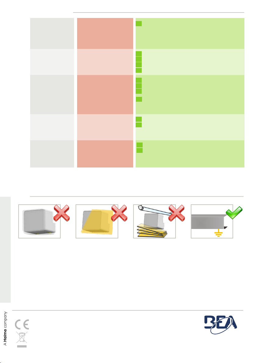
Make sure the sensor
installed firmly.
Avoid extreme vibrations.
Do not place the metallic
object in front of sensor,
or it will impact the detec-
tion effects.
Avoid proximity to neon
lamps or moving
objects.
The device cover profile
and the power supply
must be correctly earthed.
TIPS
TROUBLE SHOOTING
The Escalator is not
activated as supposed
to be.
The LED is OFF.
The sensor power is off. Check the wiring and the power supply.
The escalator is
activated/
deactivated
improperly.
The escalator keeps
running even when
nobody steps in.
The installation position, tilt
angle or the size of detection
zone of sensor is improper.
Output mode error.
Detection field range is too
large.
Power supply is not properly
grounded. Make sure the power supply
is properly grounded.
Make sure the sensor is fixed properly.
Adjust the tilt angle.
Adjust the size of detection zone.
Adjust the immunity level.
Adjust to the Pulse mode.
Set the appropriate sensitivity.
Increase the immunity level.
The LED flashes
1 x every 3 seconds.
The sensor signals an
internal fault. Cut and restore power supply.
If LED flashes again, replace sensor.
The LED flashes
2 x every 3 seconds.
Power input Check the normal range of power supply.
Replace the power supply.
1
2
4
The LED flashes
irregularly or lights up
permanently.
1
2
BEA
SA
|
LIEGE
Science
Park
|
ALLÉE
DES
NOISETIERS
5
-
4031
ANGLEUR
[BELGIUM]
|
T
+32
4
361
65
65
|
F
+32
4
361
28
58
|
[email protected] |
EU.BEASENSORS.COM
BEA hereby declares that the equipment type CGS-MF is in compliance with European Directives 2011/65/EU
(RoHS), 2014/53/EU (RED) . The full text of the EU declaration of conformity is available on our website.
For EU countries: This product should be disposed of separately from unsorted municipal waste.