Thies CLIMA First Class Advanced X User manual

Wind Transmitter
>>First Class Advanced X<<
Instruction for Use
4.3352.00.400 / 401
4.3352.10.400 / 401
- Classified according to IEC 61400-12-1 EDITION 2.0 (2017-03)
At start of software version V3.08
Dok. No. 021814/03/21
T H E W O R L D O F W E A T H E R D A T A

© Adolf Thies GmbH & Co. KG · Hauptstraße 76 · 37083 Göttingen · Germany 021814/03/21
Phone +49 551 79001-0 · Fax +49 551 79001-65 · inf[email protected] · www.thiesclima.com Page 2 of 86
Safety Instructions
•Before operating with or at the device/product, read through the operating instructions.
This manual contains instructions which should be followed on mounting, start-up, and operation.
A non-observance might cause:
- failure of important functions
- endangerment of persons by electrical or mechanical effect
- damage to objects
•Mounting
, electrical connection and wiring of the device/product must be carried out only by a qualified
technician who is familiar with and observes the engineering regulations, provisions and standards ap-
plicable in each case.
•Repairs and maintenance may only be carried out by trained staff or Adolf Thies GmbH & Co. KG.
Only components and spare parts supplied and/or recommended by Adolf Thies GmbH & Co. KG
should be used for repairs.
•Electrical devices/products must be mounted and wired only in a voltage-free state.
•Adolf Thies GmbH & Co KG guarantees proper functioning of the device/products provided that no
modifications have been made to the mechanics, electronics or software, and that the following points
are observed:
•All information, warnings and instructions for use included in these operating instructions must be
taken into account and observed as this is essential to ensure trouble-free operation and a safe condi-
tion of the measuring system / device / product.
•The device / product is designed for a specific application as described in these operating instructions.
•The device / product should be operated with the accessories and consumables supplied and/or rec-
ommended by Adolf Thies GmbH & Co KG .
•Recommendation: As it is possible that each measuring system / device / product may, under certain
conditions, and in rare cases, may also output erroneous measuring values, it is recommended using
redundant systems with plausibility checks for security-relevant applications.
Environment
•As a longstanding manufacturer of sensors Adolf Thies GmbH & Co KG is committed
to the objectives of environmental protection and is therefore willing to take back all
supplied products governed by the provisions of "ElektroG" (German Electrical and
Electronic Equipment Act) and to perform environmentally compatible disposal and
recycling. We are prepared to take back all Thies products concerned free of charge if
returned to Thies by our customers carriage-paid.
•Make sure you retain packaging for storage or transport of products. Should packag-
ing however no longer be required, please arrange for recycling as the packaging ma-
terials are designed to be recycled.
Documentation
•© Copyright Adolf Thies GmbH & Co KG, Göttingen / Germany
•Although these operating instructions have been drawn up with due care, Adolf Thies GmbH & Co
KG can accept no liability whatsoever for any technical and typographical errors or omissions in this
document that might remain.
•We can accept no liability whatsoever for any losses arising from the information contained in this doc-
ument.
•Subject to modification in terms of content.
•The device / product should not be passed on without the/these operating instructions.

© Adolf Thies GmbH & Co. KG · Hauptstraße 76 · 37083 Göttingen · Germany 021814/03/21
Phone +49 551 79001-0 · Fax +49 551 79001-65 · inf[email protected] · www.thiesclima.com Page 3 of 86
Table of contents
1Models............................................................................................................................ 6
2Application...................................................................................................................... 6
3Setup and Mode of Operation......................................................................................... 7
4Standard Curve and Calibration Tables .........................................................................11
4.1 Case 1 Using Standard Characteristic Curve acc. to Classification .........................12
4.2 Case 2 Using Current Calibration Table acc. to Classification .................................15
4.3 Determine Occupied Calibration Tables ..................................................................18
4.4 Read Calibration Table............................................................................................18
4.5 Write Calibration Table............................................................................................19
5Integrated Corrections ...................................................................................................20
5.1 Correction of the Wind Velocity Depending on the Air Pressure ..............................20
6Recommendation Side Selection / Standard Installation................................................21
7Installation......................................................................................................................21
7.1 Mechanical Mounting...............................................................................................22
7.1.1 North Alignment ................................................................................................23
7.2 Electrical Mounting..................................................................................................24
7.2.1 Cable ................................................................................................................24
7.2.2 Cable Shield......................................................................................................24
7.2.3 Plug and Cable Mounting..................................................................................26
7.3 Connecting Diagram................................................................................................27
8Maintenance..................................................................................................................28
9Firmware Version / Update ............................................................................................28
10 Bootloader .....................................................................................................................29
11 Interface.........................................................................................................................30
11.1 Command Interpreter THIES...................................................................................31
11.1.1 Telegram Formats..........................................................................................32
11.1.2 Check Sum:...................................................................................................33
11.1.3 Status Information:.........................................................................................33
11.2 Commands and Description ....................................................................................34
11.2.1 Command BR................................................................................................36
11.2.2 Command BT.................................................................................................36
11.2.3 Command CI..................................................................................................37
11.2.4 Command CK ................................................................................................37
11.2.5 Command FB.................................................................................................38
11.2.6 Command FO ................................................................................................38
11.2.7 Command HP ................................................................................................39
11.2.8 Command HT ................................................................................................39
11.2.9 Command ID..................................................................................................40
11.2.10 Command KX ................................................................................................41
11.2.11 Command KY ................................................................................................42
11.2.12 Command MI.................................................................................................43
11.2.13 Command MS................................................................................................43
11.2.14 Command OH................................................................................................44
11.2.15 Command RC................................................................................................45
11.2.16 Command RS ................................................................................................47
11.2.17 Command SF.................................................................................................47
11.2.18 Command SH................................................................................................48

© Adolf Thies GmbH & Co. KG · Hauptstraße 76 · 37083 Göttingen · Germany 021814/03/21
Phone +49 551 79001-0 · Fax +49 551 79001-65 · inf[email protected] · www.thiesclima.com Page 4 of 86
11.2.19 Command SM................................................................................................49
11.2.20 Command SN ................................................................................................50
11.2.21 Command SR................................................................................................50
11.2.22 Command SV ................................................................................................50
11.2.23 Command TR ................................................................................................51
11.2.24 Command UC................................................................................................51
11.2.25 Command WC...............................................................................................52
11.3 Command Interpreter MODBUS RTU......................................................................53
11.3.1 Measured Values (Input Register)..................................................................54
11.3.2 Commands (Holding Register).......................................................................62
11.3.3 Calibration Tables in the MODBUS-RTU Interpreter......................................62
11.3.4 Reading Time Stamp of all Calibration Tables ...............................................63
11.3.5 Reading Calibration Tables............................................................................64
11.3.6 Device identification (Read Device Identification)...........................................68
12 Appendix 1 Data Telegrams...........................................................................................69
12.1 Telegram 1..............................................................................................................69
12.2 Telegram 2..............................................................................................................72
12.3 Telegram 4..............................................................................................................73
12.4 Telegram 5..............................................................................................................74
12.5 Telegram 6..............................................................................................................75
12.6 Measured Value Memory Telegram.........................................................................76
13 Technical Data...............................................................................................................79
14 FAQ - Frequently Asked Questions................................................................................80
15 Dimensional Drawing.....................................................................................................81
16 Accessories (optional)....................................................................................................82
17 EC-Declaration of Conformity ........................................................................................84
Table overview:
Table 1 : Status Word...........................................................................................................34
Table 2 : Command List .......................................................................................................35
Table 3 : MODBUS Frame ...................................................................................................53
Table 4: MODBUS Exceptions .............................................................................................53
Table 5 : MODBUS Input Register........................................................................................60
Table 6: Calibration Tables...................................................................................................63
Table 7: Reading Time.........................................................................................................64
Table 8: Reading Calibration................................................................................................67
Table 9: Device Identification................................................................................................68
Table 10: Measured Value Telegram....................................................................................71
Table 11 : Measured Value Telegram 2................................................................................73
Table 12: Value-Telegram 4.................................................................................................74
Table 13: Measured value telegram 5 ..................................................................................74
Table 14: Value-Telegram 6.................................................................................................76
Table 15 : Measured Value Memory Telegram.....................................................................77

© Adolf Thies GmbH & Co. KG · Hauptstraße 76 · 37083 Göttingen · Germany 021814/03/21
Phone +49 551 79001-0 · Fax +49 551 79001-65 · inf[email protected] · www.thiesclima.com Page 5 of 86
Figure:
Figure 1: Connections between parameters FO, MS and UC................................................ 8
Figure 2: Curve of a calibration table and normal curve........................................................11
Figure 3: Data output after calibration E433524X0 2.3 in order to have frequency output at
pin 1 according to the classification with standard characteristic curve..........................13
Figure 4: Data output after calibration E433524X2 2.3 in order to have serial output
according to the classification with standard characteristic curve...................................14
Figure 5: Data output after calibration E433524X1 2.3 in order to have frequency output at
pin 1 according to the classification with current calibration table...................................16
Figure 6: Data output after calibration E433524X3 2.3 in order to have serial output
according to the classification with current calibration table...........................................17
Patent
This device is protected by patents.
Patent no.: EP 1 398 637
Patent no.: DE 103 27 632
Patent no.: EP 1 489 427

© Adolf Thies GmbH & Co. KG · Hauptstraße 76 · 37083 Göttingen · Germany 021814/03/21
Phone +49 551 79001-0 · Fax +49 551 79001-65 · inf[email protected] · www.thiesclima.com Page 6 of 86
1 Models
Order no. Measuring
range
Serial interface /
Data format Supply Heater
4.3352.00.400 0,3 ... 75m/s RS 485 / ASCII 3,7 … 42V DC 24V AC/DC, 25W
4.3352.10.400 0,3 ... 75m/s RS 485 / ASCII 3,7 … 42V DC without
4.3352.00.401 0,3 ... 75m/s RS 485 / MODBUS 3,7 … 42V DC 24V AC/DC, 25W
4.3352.10.401 0,3 ... 75m/s RS 485 / MODBUS 3,7 … 42V DC without
The following parts are included in the scope of delivery:
1 x Wind transmitter.
1 x Connection plug.
1 x Instructions for use.
2 Application
The wind transmitter is intended for use in the wind energy, meteorology and environmental
measuring technology. Primarily developed for position evaluation and measurement of power
curves of wind turbines, the anemometer gathers the following measured variables:
•Horizontal component of the wind velocity.
•Absolute and relative air pressure.
•Inclination angle between the Z-axis and the vertical.
•Inclination angle between the X-axis and the horizontal.
•Inclination angle between the Y-axis and the horizontal.
•Frequency and acceleration in the X-, Y- and Z-axis.
•Housing interior temperature.
Further characteristics include a defined and optimized dynamic behavior even at highly in-
tense turbulences, minimal over speeding, a low starting value and an optimized oblique inflow
behavior.
An integrated compensation of the effect of the air density on the rotation velocity of the cup
star distinguishes this sensor especially in its characteristics.
There is a digital interface to the device in form of an RS485 interface in half-duplex mode.
Together with the ID-based communication, the interface enables the operation of the wind
transmitter in a bus. Tow data protocols are available:
•ASCII (THIES format).
•Binary (MODBUS-RTU).
For operation in winter, the device can be equipped optionally with an electronically controlled
heater which provides a hardly measurable friction moment of the ball bearings in low temper-
atures and prevents any ice build-up on shaft and on the gap.

© Adolf Thies GmbH & Co. KG · Hauptstraße 76 · 37083 Göttingen · Germany 021814/03/21
Phone +49 551 79001-0 · Fax +49 551 79001-65 · inf[email protected] · www.thiesclima.com Page 7 of 86
3 Setup and Mode of Operation
The wind transmitter can be supplied with direct voltages from 3.7V up to 42V at very low
power consumption. All of the electronics is a streamlined, low power design. Supply of the
optional heater is provided separately with a direct or alternate voltage of 24V. The heater
will most probably prevent icing/clogging of the wind transmitter First Class even under ex-
treme meteorological conditions.
The external parts of the device are made from corrosion resistant anodized aluminum.
Highly efficient labyrinth seals and O-rings protect the sensitive parts on the inside of the de-
vice from humidity and dust influences. It is assembled on a mast pipe, the electric connec-
tion is in the lower part of the sensor.
Wind Velocity:
A cup star with ball bearing and low inertia and 3 cups from carbon fiber reinforced plastic is
rotated by the wind. The velocity is sensed opto-electronically, translated into a square signal
with frequency proportional to the velocity and measured 4 times per second. The measured
frequency is converted into a wind velocity with the standard curve. An adaptation of this
standard curve can be done with calibration values from a programmable calibration table
(Standard curve and calibration tables).
The compensation depending on the air pressure which is calculated with the help of the cali-
bration table.
All corrected wind velocity values are available as instantaneous values. The Instantaneous
value is the gliding mean value of the last second.
For the calculation of mean value, gust, minimum value, standard deviation and intensity of
turbulence the source can be selected by the command „MS“.
The following figures show the described connection.

© Adolf Thies GmbH & Co. KG · Hauptstraße 76 · 37083 Göttingen · Germany 021814/03/21
Phone +49 551 79001-0 · Fax +49 551 79001-65 · inf[email protected] · www.thiesclima.com Page 8 of 86
Figure 1: Connections between parameters FO, MS and UC

© Adolf Thies GmbH & Co. KG · Hauptstraße 76 · 37083 Göttingen · Germany 021814/03/21
Phone +49 551 79001-0 · Fax +49 551 79001-65 · inf[email protected] · www.thiesclima.com Page 9 of 86
Instantaneous value:
The instantaneous value is the gliding mean value of the last second. The scanning of the
measuring values is carried out every 0.25s, and is not alterable. The measuring value, que-
ried at any time, includes always the data of the last second measured in the moment of
query.
Note:
From firmware version V02.09, is the interval of the gliding mean value one
second. All older versions work with an interval of 3 seconds.
Mean value:
The mean value is the gliding mean value of the last ‚n‘ seconds. ‚n‘ is defined by the param-
eter MI.
Minimum:
The minimum specifies the minimum instantaneous value of the last minute.
Gust:
The gust is the maximum instantaneous value of the last minute.
Air pressure:
A highly precise digital pressure sensor (piezoresistive) is used to measure the absolute air
pressure. The wind transmitter calculates the relative air pressure with the set altitude (com-
mand SH).
Note: The absolute air pressure is used for application of the wind velocity compensation by
means of air pressure. Indicating the sensor height by parameter SH is not required.
Inner Housing temperature:
An integrated, digital temperature sensor measures the internal temperature of the housing.
Inclination/vibration:
The measurement of the acceleration in space is done via a 3-axis acceleration sensor. The
wind transmitter will calculate the inclination angle and vibrations (frequency and accelera-
tion).
The inclination measurement is basing on the measurement of the acceleration of gravity.
The three sensitive axes of the sensor are sensitive each only in one direction, thus only that
value of the gravity acceleration is measured which affects in direction of these axes. The
slope of the sensor in space is calculated from these three measuring values.

© Adolf Thies GmbH & Co. KG · Hauptstraße 76 · 37083 Göttingen · Germany 021814/03/21
Phone +49 551 79001-0 · Fax +49 551 79001-65 · inf[email protected] · www.thiesclima.com Page 10 of 86
The angle ρis defined as angle between the x-axis (north – south axis), and the horizontal.
The angle Φis defined as angle between the y-axis (west – east axis), and the horizontal.
The angle θis the angle between the z-axis, and the vertical.
Based on the angle, frequency and acceleration (amplitude), a qualified mast monitoring is
possible.
Frequency output:
In the pre-setting the incorrected pulse values of the sensor are delivered on the frequency
output. It behaves according to 4.3351.x0.000. The behavior of the frequency output is set by
parameter FO.
Intensity of turbulence:
The intensity of turbulence is calculated from the instantaneous
values of the wind velocity.
SD: Standard deviation wind velocity
xi: instantaneous value wind velocity
/x: mean value wind velocity
T: Intensity of turbulence

© Adolf Thies GmbH & Co. KG · Hauptstraße 76 · 37083 Göttingen · Germany 021814/03/21
Phone +49 551 79001-0 · Fax +49 551 79001-65 · inf[email protected] · www.thiesclima.com Page 11 of 86
4 Standard Curve and Calibration Tables
The measured frequency is converted into a wind velocity (in proportion to the velocity of the
cup star) with the standard curve:
21,00462,0 +•= fy
y: Wind velocity in [m/s]
f: Frequency in [Hz]
Note:
At frequencies less then 2Hz will be set the wind velocity to 0m/s.
The standard curve can be corrected via a programmable calibration table with 32 entries.
The wind transmitter can save up to 10 calibration tables, including calibration certificate
number, user-defined text, date and time of the calibration.
The entries within the calibration table are in form of X/Y value pairs. The X-values corre-
spond to the actual wind velocity in m/s with 2 decimal places and the Y-values correspond
to the related target wind velocity, also in m/s with 2 decimal places.
All entries of a non-programmed, i.e. unfilled table, are set on 0xffff.
It’s not required to fill all 32 places in the table. The characteristic curve must represent part
of the measuring range. The entries in the calibration tables have to start with the first index
and must be continuing.
The following figure shows the relationship between a calibration table, the normal curve and
the approximation outside the calibration area.
Figure 2: Curve of a calibration table and normal curve
Blue: standard characteristic curve, red: calibration curve, green: interpolation outside the
calibration curve

© Adolf Thies GmbH & Co. KG · Hauptstraße 76 · 37083 Göttingen · Germany 021814/03/21
Phone +49 551 79001-0 · Fax +49 551 79001-65 · inf[email protected] · www.thiesclima.com Page 12 of 86
If the measured actual wind velocity is between 2 entries of the table, the wanted target wind
velocity is determined by linear interpolation.
If the measured actual wind velocity is outside the table range, the Bit2 is set in the status
word and the standard curve is interpolated as follows:
- Is the measurement below the curve range, we have to interpolate between the start-
ing point of the standard curve and the first table value.
- Is the measurement above the curve range, we have to interpolate between the last
table value and the wind velocity 75m/s at the standard curve.
For the calculation of the corrected wind velocity, the calibration table last created is used.
Note:
After setting the time stamp, the calibration table can no longer changed.
Please see the question and answers in FAQ 14. Frequently Ask Questions.
4.1 Case 1 Using Standard Characteristic Curve acc. to Classifica-
tion
The optimum way would be as specified below:
Ia. First you must specify whether you want to use the frequency output (pin 1) or serial
output to get your data
Ib. Calibration must be done without regard to the air pressure. For calibration you must
tell what kind of output you want to use in operation:
frequency output (pin 1) calibration data: wind velocity corrected by standard
characteristic curve at pin 1; FO2
serial output calibration data: wind velocity corrected by standard characteristic
curve at telegram 2 pos. 11
Ic. Let the linear regression analysis (slope / offset) on the calibration certificate be done
for the calibration data
Note:
Steps Ib. and Ic. will be done automatically if you order the calibration according to Thies art.
no. E433524X0 2.3 (for frequency output (pin 1); see picture 2) resp. E433524X2 2.3 (for se-
rial output; see picture 3).

© Adolf Thies GmbH & Co. KG · Hauptstraße 76 · 37083 Göttingen · Germany 021814/03/21
Phone +49 551 79001-0 · Fax +49 551 79001-65 · inf[email protected] · www.thiesclima.com Page 13 of 86
Figure 3: Data output after calibration E433524X0 2.3 in order to have frequency output at pin 1
according to the classification with standard characteristic curve

© Adolf Thies GmbH & Co. KG · Hauptstraße 76 · 37083 Göttingen · Germany 021814/03/21
Phone +49 551 79001-0 · Fax +49 551 79001-65 · inf[email protected] · www.thiesclima.com Page 14 of 86
Figure 4: Data output after calibration E433524X2 2.3 in order to have serial output according to
the classification with standard characteristic curve

© Adolf Thies GmbH & Co. KG · Hauptstraße 76 · 37083 Göttingen · Germany 021814/03/21
Phone +49 551 79001-0 · Fax +49 551 79001-65 · inf[email protected] · www.thiesclima.com Page 15 of 86
For using frequency output (pin 1) next steps are as following:
Id. For operation, set FO4, UC0
Ie. Collect data from frequency output. With this setting, you will get wind velocity
corrected by standard characteristic curve and air pressure (so classification and
calibration are applicable). This is without regard to the firmware version
These are the next steps for using serial output:
If. For operation set UC0, MS2
Ig. For type *.400 (RS485) collect data v(hPa corr.) from telegram 2 / 4 / 5 / 6 pos. 17 (so
classification and calibration are applicable). This is without regard to the firmware
version
Ih. For type *.401 (MODBUS) collect data v(hPa corr.) from register 30013 / 35013 /
36005 / 36105 / 36205 (so classification and calibration are applicable). This is
without regard to the firmware version
4.2 Case 2 Using Current Calibration Table acc. to Classification
The procedure will be as following:
IIa. First you must specify whether you want to use the frequency output (pin 1) or serial
output to get your data
IIb. Calibration must be done without regard to the air pressure. For calibration you must
tell what kind of output you want to use in operation:
frequency output (pin 1) calibration data: wind velocity corrected by standard
characteristic curve at pin 1; FO2
serial output calibration data: wind velocity corrected by standard characteristic
curve at telegram 2 pos. 11
IIc. Let the linear regression analysis (slope / offset) on the calibration certificate be done
for the calibration data
IId. Let write the first calibration results into the current calibration table of the device. The
first calibration is then an adjustment
IIe. Storing the current calibration table on the device and using this data subsequently
for calculating the wind speed values means changing the device in a certain way.
Therefore, from the purely formal point of view a re-calibration would need to be
done. However, the re-calibration in this case would show a deviation of (nearly) 0.
Note:
Steps IIb. to IIe. will be done automatically if you order the calibration according to Thies art.
no. E433524X1 2.3 (for frequency output (pin 1); see picture 4) resp. E433524X3 2.3 (for se-
rial output; see picture 5).

© Adolf Thies GmbH & Co. KG · Hauptstraße 76 · 37083 Göttingen · Germany 021814/03/21
Phone +49 551 79001-0 · Fax +49 551 79001-65 · inf[email protected] · www.thiesclima.com Page 16 of 86
Figure 5: Data output after calibration E433524X1 2.3 in order to have frequency output at pin 1
according to the classification with current calibration table

© Adolf Thies GmbH & Co. KG · Hauptstraße 76 · 37083 Göttingen · Germany 021814/03/21
Phone +49 551 79001-0 · Fax +49 551 79001-65 · inf[email protected] · www.thiesclima.com Page 17 of 86
Figure 6: Data output after calibration E433524X3 2.3 in order to have serial output according to
the classification with current calibration table

© Adolf Thies GmbH & Co. KG · Hauptstraße 76 · 37083 Göttingen · Germany 021814/03/21
Phone +49 551 79001-0 · Fax +49 551 79001-65 · inf[email protected] · www.thiesclima.com Page 18 of 86
For using frequency output (pin 1) next steps are as following:
IIf. For operation, set FO4, UC1
IIg. Collect data from frequency output. With this setting, you will get wind velocity
corrected by current calibration table and air pressure (so classification and
calibration are applicable). This is without regard to the firmware version
These are the next steps for using serial output:
IIh. For operation set UC1, MS2
IIi. For type *.400 (RS485) collect data v(hPa corr.) from telegram 2 / 4 / 5 / 6 pos. 17 (so
classification and calibration are applicable). This is without regard to the firmware
version
IIj. For type *.401 (MODBUS) collect data v(hPa corr.) from register 30013 / 35013 /
36005 / 36105 / 36205 (so classification and calibration are applicable). This is
without regard to the firmware version
4.3 Determine Occupied Calibration Tables
In order to query the free and the already occupied calibration tables, the Command RC can
be used with parameter 99. In the response string for the command “RC99”, the wind trans-
mitter will output the time stamp of all 10 calibration tables. The time stamps are divided by
the semicolon.
Example:
01RC99\r
2016.04.12;11:12:00;2010.00.00;00:00:00;2010.00.00;00:00:00;2010.00.00;00:00:00;2010.0
0.00;00:00:00;2010.00.00;00:00:00;2010.00.00;00:00:00;2010.00.00;00:00:00;2010.00.00;00
:00:00;2010.00.00;00:00:00;
4.4 Read Calibration Table
Reading the data from the calibration tables is done with the Command RC. The parameter
will indicate the calibration table to be read (0: standard curve, 1 ... 10: Calibration tables). In
the response for the command “RC<parameter>”, the wind transmitter will output all 32 table
entries and calibration certificate number, user-defined text and time stamp of the table.
Example:
01RC1\r
00000;00000;00242;00242;00484;00484;00726;00726;00968;00968;01210;01210;01452;01
452;01694;01694;01936;01936;02178;02178;02420;02420;02662;02662;02904;02904;0314
6;03146;03388;03388;03630;03630;03872;03872;04114;04114;04356;04356;04598;04598;0
4840;04840;05082;05082;05324;05324;05566;05566;05808;05808;06050;06050;06292;062
92;06534;06534;06776;06776;07018;07018;07260;07260;07502;07502;0000001234;Test
;2016.04.12;11:12:00

© Adolf Thies GmbH & Co. KG · Hauptstraße 76 · 37083 Göttingen · Germany 021814/03/21
Phone +49 551 79001-0 · Fax +49 551 79001-65 · inf[email protected] · www.thiesclima.com Page 19 of 86
4.5 Write Calibration Table
Writing a calibration table is done with the command WC. With the parameter, the address
to be written, and target and actual value of the sampling point (or calibration certificate num-
ber or user string or date/time) will be specified.
The written table entry is delivered back with the response telegram.
When writing in a calibration table, the next free table is always used. Writing into the
memory of a table can be repeated as often as required as long as the memory for date/time
is still empty.
A table is only used for the calculations if it has been completed with the date/time infor-
mation.
The following flow diagram shows the process of writing a calibration table:
Start
I < number?
I=0 aa=1
<id>WC<Parameter><CR>
Parameters = aa;sssss;iiiii;
Return value = tt;aa;sssss;iiiii
tt = table
aa = address (1...32)
sssss = target wind velocity in 0.01 [m/s]
iiiii = actual wind velocity in 0.01 [m/s]
yes
no
I++ aa++
<id>KYxxxxx<CR>
Determine calibration values
Number = measured value
Number = 2 ...32
Initialisation
Set password,
with xxxxx: value
from parameter CK
Determining target/actual
values (the wind velocities
calculated with the standard
curve are used as actual
values
Write sampling
point
<id>WC<Parameter><CR>
Parameter = 33;xxxxxxxxxx;
Return value = tt;aa; xxxxxxxxxx
xxxxxxxxxx = calibration certificate number
Write calibration
certificate

© Adolf Thies GmbH & Co. KG · Hauptstraße 76 · 37083 Göttingen · Germany 021814/03/21
Phone +49 551 79001-0 · Fax +49 551 79001-65 · inf[email protected] · www.thiesclima.com Page 20 of 86
5 Integrated Corrections
The measured values for wind velocity and air pressure are corrected in the transmitter and
can be queried with the measured value telegram 3.
The following corrections are implemented:
- Correction of the wind velocity depending on the air pressure.
5.1 Correction of the Wind Velocity Depending on the Air Pressure
The rotational velocity of the cup star depends on the air density and thus on the air pres-
sure. The correction of this dependency is done in a pressure range of 700hPa to 1100hPa.
<id>WC<Parameter><CR>
Parameter = 35;YYYY.MM.DD;HH:NN:SS;
Return value = tt;aa;YYYY.MM.DD;HH:NN:SS
tt = table
aa = 35 (address for date/time)
YYYY: Year MM: Month
DD: Day HH: Hour
NN: Minute SS: Second
End
KY=0
Write date/time
Reset password
<id>WC<Parameter><CR>
Parameter = 34;uuuuuuuuuuuuuuu;
Return value = tt;aa;uuuuuuuuuuuuuuuu
uuuuuuuuuuuuuuuu = user-defined text
Write user string
UC=1
Activation of
calibration table
This manual suits for next models
4
Table of contents
Other Thies CLIMA Measuring Instrument manuals
Thies CLIMA
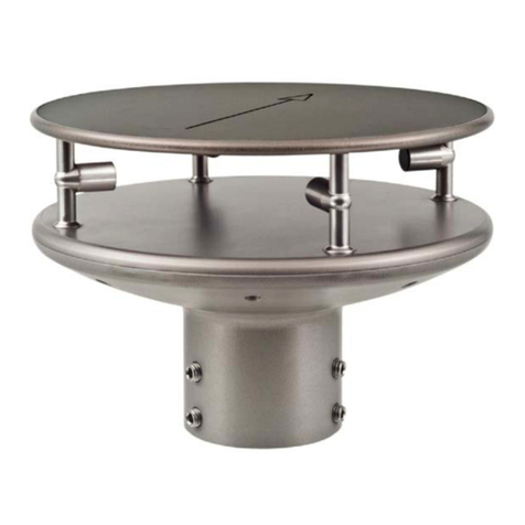
Thies CLIMA 4.387 Series User manual

Thies CLIMA
Thies CLIMA 4.3223.50 Series User manual
Thies CLIMA
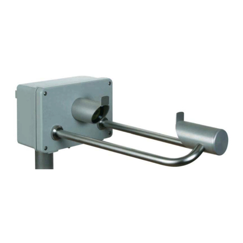
Thies CLIMA 5.4110 00 Series User manual

Thies CLIMA
Thies CLIMA 9.2750.xx.90 Series User manual

Thies CLIMA
Thies CLIMA Hygro-Thermo Transmitter-compact User manual
Thies CLIMA
Thies CLIMA Ultrasonic Anemometer 2D User manual


