Thies CLIMA 5.4110 00 Series User manual

THE WORLD OF WEATHER DATA - THE WORLD OF WEATHER DATA - THE WORLD OF WEATHER DATA
Instruction for Use
021341/07/11
Laser Precipitation Monito
r
5.4110.xx.x00
V
2.5x STD
INVISIBLE LASER RADIATION
DO NOT VIEW DIRECTLY WITH
OPTICAL INSTRUMENTS
CLASS 1M LASER PRODUCT
ADOLF THIES GmbH & Co. KG
Hauptstraße 76 37083 Göttingen Germany
Box 3536 + 3541 37025 Göttingen
Phone +49 551 79001-0 Fax +49 551 79001-65

Safety Instructions
• Before operating with or at the device/product, read through the operating instructions.
This manual contains instructions which should be followed on mounting, start-up, and operation.
A non-observance might cause:
- failure of important functions
- Endangering of persons by electrical or mechanic effect
- Damages at objects
• Mounting, electrical connection and wiring of the device/product must be carried out only by a qualified technician
who is familiar with and observes the engineering regulations, provisions and standards applicable in each case.
• Repairs and maintenance may only be carried out by trained staff or Adolf Thies GmbH & Co. KG. Only
components and spare parts supplied and/or recommended by Adolf Thies GmbH & Co. KG should be used for
repairs.
• Electrical devices/products must be mounted and wired only in voltage-free state.
• Adolf Thies GmbH & Co KG guarantees proper functioning of the device/products provided that no
modifications have been made to the mechanics, electronics or software, and that the following points are
observed:
• All information, warnings and instructions for use included in these operating instructions must be taken into
account and observed as this is essential to ensure trouble-free operation and a safe condition of the measuring
system / device / product.
• The device / product is designed for a specific application as described in these operating instructions.
• The device / product should be operated with the accessories and consumables supplied and/or recommended
by Adolf Thies GmbH & Co KG .
• Recommendation: As it is possible that each measuring system / device / product under certain conditions, and
in rare cases, may also output erroneous measuring values, it is recommended to use redundant systems with
plausibility checks with security-relevant applications.
Environment
• As a longstanding manufacturer of sensors Adolf Thies GmbH & Co KG is committed to the
objectives of environmental protection and is therefore willing to take back all supplied products
governed by the provisions of "ElektroG" (German Electrical and Electronic Equipment Act)
and to perform environmentally compatible disposal and recycling. We are prepared to take
back all Thies products concerned free of charge if returned to Thies by our customers
carriage-paid.
• Make sure you retain packaging for storage or transport of products. Should packaging
however no longer be required, arrange for recycling as the packaging materials are designed
to be recycled.
Documentation
• © Copyright Adolf Thies GmbH & Co KG, Göttingen / Germany
• Although this operating instruction has been drawn up with due care, Adolf Thies GmbH & Co KG can accept
no liability whatsoever for any technical and typographical errors or omissions in this document that might
remain.
• We can accept no liability whatsoever for any losses arising from the information contained in this document.
• Subject to modification in terms of content.
• The device / product should not be passed on without the/these operating instructions.
2 - 66 021341/07/11

3 - 66 021341/07/11
Contents
1Models .......................................................................................................................................5
2General......................................................................................................................................5
3Mode of Operation of the Laser Precipition Monitor ..................................................................6
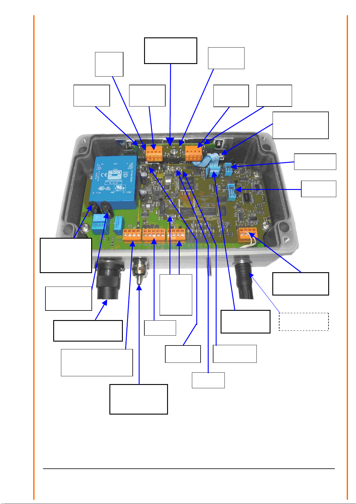
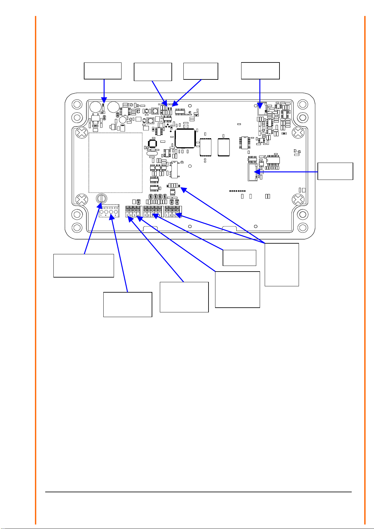
4Construction of the Measuring Instrument.................................................................................8
4.1 Heating..............................................................................................................................12
4.1.1 Variant Extended Heating (5.4110.x1.xxx) .................................................................12
5Installation................................................................................................................................13
5.1 Suggestions for Mounting Place........................................................................................ 13
5.2 Mechanical Installation......................................................................................................14
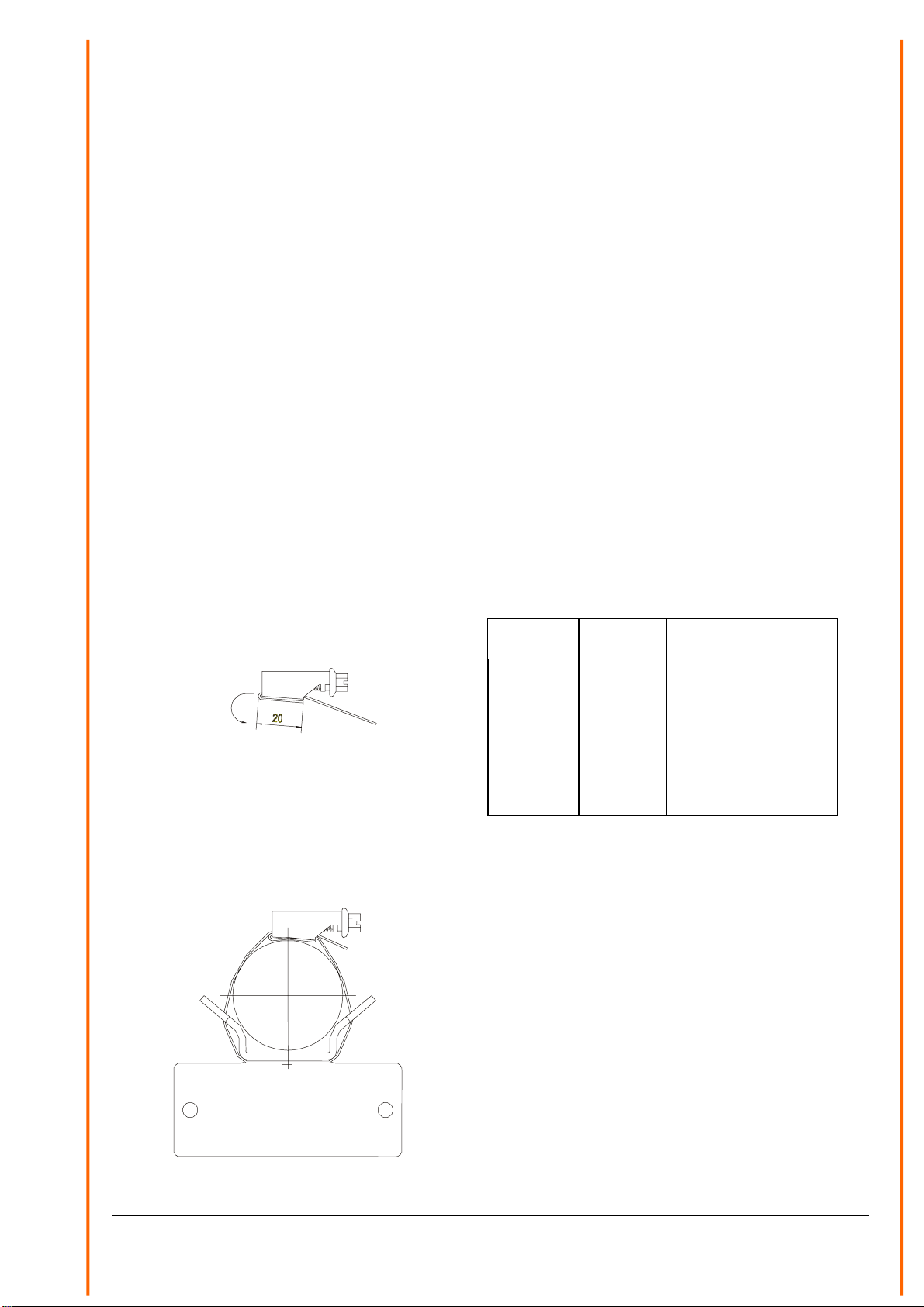
5.2.1 Mounting on Mast.......................................................................................................14
5.2.1.1 Example ...............................................................................................................15
5.2.2 Mounting Angle...........................................................................................................16
5.2.3 Mounting of the Housing Cover .................................................................................. 17
5.3 Electrical Installation..........................................................................................................17
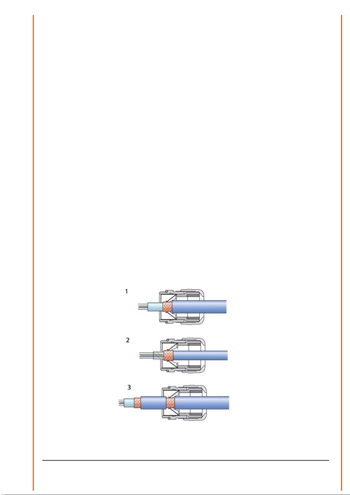
5.3.1 Electrical installation with cable glands.......................................................................18
5.3.1.1 Electrical Installation via Connector ..................................................................... 20
5.3.2 Closing the Instrument Cover ..................................................................................... 20
5.3.3 Optocoupler output.....................................................................................................20
6Maintenance ............................................................................................................................21
6.1 Cleaning............................................................................................................................ 21
6.2 Calibration......................................................................................................................... 21
6.3 Checking the sensor.......................................................................................................... 21
6.3.1 Checking the LED’s....................................................................................................22
6.3.2 Checking by means of a terminal program.................................................................23
7Serial communication...............................................................................................................24
7.1 General telegram format ...................................................................................................25
7.2 List of Commands .............................................................................................................26
7.2.1 Communication commands ........................................................................................27
7.2.2 Reset / Version commands......................................................................................... 28
7.2.3 Data telegrams commands.........................................................................................29
7.2.4 Time / Date commands...............................................................................................30
7.2.5 Diagnostics commands............................................................................................... 32
7.2.6 Calibration commands................................................................................................36
7.2.7 Quantity measurement commands.............................................................................37
7.2.8 Digital output commands............................................................................................ 38
7.3 Data Telegrams.................................................................................................................42
7.3.1 Telegram 4/5: Synop, Metar, Disdrometer, optional measuring channel.................... 42
7.3.2 Telegram 6/7: Synop, Metar, optional measuring channel ......................................... 51

4 - 66 021341/07/11
7.3.3 Telegram 8/9: Synop, Metar, optional measuring channel truncated ......................... 52
7.3.4 Telegram 10: Synop, Metar, optional measurement channels, averaging.................. 54
7.3.5 Telegram 3: Particle-Event ......................................................................................... 56
8Technical Data......................................................................................................................... 57
9Wiring Diagram........................................................................................................................ 61
10 EC-Declaration of Conformity............................................................................................... 64
Figure
Figure 1: Measurement of the precipitation particle.........................................................................6
Figure 2: Explanation of the measuring principle.............................................................................6
Figure 3 :Schematic Block Diagram.................................................................................................8
Figure 4: Side view...........................................................................................................................9
Figure 5: View from above ...............................................................................................................9
Figure 6: View of the electronics Rev.B .........................................................................................10
Figure 7: View of the electronics Rev.A .........................................................................................11
Figure 8: Example for an appropriate mast foundation .................................................................. 15
Figure 9: Strap housing..................................................................................................................16
Figure 10 : Strap, Mast, Mounting angle ........................................................................................ 16
Figure 11: Screen cable connection to the cable gland .................................................................18
Figure 12: Connection of power supply (here 115 or 230VAC) with ferrite tube and binder.......... 19
Figure 13: Examples for the connection to the opto-couplers........................................................20
Table
Table 1: Example for the speed of liquid particles............................................................................ 7
Table 2: List of baud rates with telegram BR .................................................................................27
Table 3: Parameter D1/D2 command............................................................................................. 39
Table 4: Parameter 17 (command D1 and D2) ..............................................................................40
Table 5: Parameter 19 (command D1 and D2) ..............................................................................41
Table 6: Disdrometer class binning of diameter and speed...........................................................48
Table 7: Code table SYNOP/METAR............................................................................................. 49
Table 8: Intensity steps SYNOP..................................................................................................... 50
Tabelle 9: Intensity steps METAR..................................................................................................50

5 - 66 021341/07/11
1 Models
Order-No. Operating
Voltage Option
Meas. Channel Option
Extended Heating Tye of
Connection
5.4110.00.000 24V ~/= AC/DC Nein Nein Cable gland
5.4110.00.100 115V~ AC Nein Nein Cable gland
5.4110.00.200 230V~ AC Nein Nein Cable gland
5.4110.00.300 12...24V= DC Nein Nein Cable gland
5.4110.10.000 24V ~/= AC/DC Ja Nein Cable gland
5.4110.10.100 115V~ AC Ja Nein Cable gland
5.4110.10.200 230V~ AC Ja Nein Cable gland
5.4110.10.300 12...24V= DC Ja Nein Cable gland
5.4110.01.000 24V + 26V ~/= AC/DC Nein Ja Cable gland
5.4110.01.100 115V~ AC Nein Ja Plug connecting +
Cable gland
5.4110.11.100 115V~ AC Ja Ja Plug connecting +
Cable gland
5.4110.01.200 230V~ AC Nein Ja Plug connecting +
Cable gland
5.4110.11.200 230V~ AC Ja Ja Plug connecting +
Cable gland
Electrical outputs for all versions: RS485/422 and two optocouplers.
2 General
The Laser Precipitation Monitor serves as measuring value transmitter, and is well-suited for the
measurement and detection of different types of precipitation such as drizzle, rain, hail, snow, and
mixed precipitation.
The acquisition comprises the types of precipitation, intensity, and the spectrum. All measuring
values are available for the user via an RS 485/422 interface. In addition, the instrument is
equipped with two digital outputs (optocouplers), which indicates, for example, amount and state of
precipitation. The optical components are equipped with an integrated heating.
Instruments with „optional measuring channels” are able to connect temperature, rel. humidity, wind
speed, and wind direction sensors in addition. These values are available, as well, via the RS
485/422 interface.
On sites with rough climate the version “extended heating” is available.

3 Mode of Operation of the Laser Precipition Monitor
A laser-optical beaming source (laser diode and optics) produces a parallel light-beam (infrared,
785 nm, not visible). A photo diode with a lens is situated on the receiver side in order to measure
the optical intensity by transforming it into an electrical signal.
228 mm
0.75mm
20mm
Particle
Infrared light beam
Figure 1: Measurement of the precipitation particle
When a precipitation particle falls through the light beam (measuring area 45,6cm²(7inch²)) Figure
1: Measurement of the precipitation particle) the receiving signal is reduced. The diameter of the
particle is calculated from the amplitude of the reduction. Moreover, the fall speed of the particle is
determined from the duration of the reduced signal.
Figure 2: Explanation of the measuring principle
The measured values are processed by a signal processor (DSP), and checked for plausibility (e.g.
edge hits). Calculation comprises the intensity, quantity, and type of precipitation (drizzle, rain,
snow, soft hail, hail as well as mixed precipitation), and the particle spectrum (distribution of the
particles over the class binning).
The type of precipitation is determined from the statistic proportion of all particles referring to
diameter, and velocity. These proportions have been tested scientifically (e.g. Gunn, R., and
Kinzer, G.D., 1949, "The terminal velocity of fall for water droplets in stagnant air," J. of
Meteorology, Vol. 6, pp. 243–248). In addition, temperature is included in order to improve the
identification: Precipitations with a temperature of above 9 °C are automatically accepted as liquid
(exception: soft hail, and hail), and with a temperature of below –4°C as solid. In the temperature
range between, all forms of precipitation might occur.
6 - 66 021341/07/11

7 - 66 021341/07/11
Diameter [mm] Fall speed [m/s]
0.2 (drizzle) 0.73
0.3 (drizzle) 1.2
0.8 (rain) 3.3
0.9 (rain) 3.7
1.8 (rain) 6.1
2.2 (rain) 6.9
3.2 (rain) 8.3
5.8 (rain) 9.2
Table 1: Example for the speed of liquid particles
The calculated data are memorized over one minute, and then transmitted via the serial interface.
The instrument is almost maintenance-free. Only the panes of the sensor heads should be cleaned,
if necessary. An application all the year round is guaranteed by the integrated pane-heating. For
application in areas of extreme weather conditions (for example high mountains) we recommend a
model with “extended heating”. The effect of external light is minimized by a modulated light source
of 173kHz (so-called „Lock-In“ technology). The effect of aging and temperature on the components
as well as the soiling of the glass panes is compensated by controlling the receiving capacity. A
watch-dog device controls the signal processor (DSP). The sensor controls its function by
measuring and checking the receiving signals for soiling, as well as checking the laser driver for
current and temperature. By using a flash-memory the internal software can be updated any time
via the serial interface.
The following outputs are available: an electrically isolated serial interface (RS485) as well as two
digital outputs (optocoupler). Thanks to the configurable digital outputs this sensor can be used as
an alternative for precipitation monitors (e.g. IRSS88 or Thies 5.4103.10.000), and for precipitation
sensors (e.g. tipping bucket).
The function of the digital outputs is programmable. For example: output 1
0,1mm or 0,01 resp. 0,005 mm precipitation per pulse corresponding to the cumulatively measured
precipitation quantity. Output 2, for example, as precipitation event monitor, or as additional event
output „solid precipitation“ (snow, snow-grains, soft hail, hail) in conjunction with output 1.
In addition, the following sensors can be connected optionally („Option Measuring Channels”):
• temperature (Pt100, not available with option “Extended Heating”)
• relative humidity (0-1V / 0-100% rel. humidity)
• wind speed (frequency 0- 630 Hz for example 4.3519.00.000)
• wind direction (serially synchronous for example 4.3129.00.000)

Figure 3 :Schematic Block Diagram
In explanation of the construction, and the basic function the block diagram Figure 3) shows
schematically the most important functional connections (variant “Extended Heating” not shown).
4 Construction of the Measuring Instrument
The Laser Precipitation Monitor consists of the following: a varnished aluminium housing, protection
IP 65, a laser head ( anodised aluminium), fixed at the housing cover, a receiver head (anodised
aluminium) fastened by means of carrier arms (see also Figure 4 and Figure 5)
The aluminium housing contains the electronics with all necessary interfaces. Furthermore, the
electronics is equipped with light diodes (LED’s), which facilitate an easy and efficient check resp.
diagnosis of the sensor even without serial data connection (Figure 6 or Figure 7. In the chapter
“Maintenance” (see Ch. 6) you find a functional description of the LED’s.
The replaceable laser head consists of a laser driver circuit board (incl. laser diode), a rectangular
window for the beam forming, a lens and a heated glass pane. The electrical connection to the
electronics is carried out by a 10-pole ribbon flat cable leading to the “Connector Laser”.
The receiver head consists of a receiving circuit board with photo diode and electronics, a lens and
a heated glass pane. The electrical connection is done by a 6-pole ribbon flat cable leading to the
“Connector Receiver”.
8 - 66 021341/07/11

Attention:
Do not look into the invisible laser beam! In case the laser
caution labels on the housing are not legible any more the
sensor must not be operated!
Even with a longer exposure time the intensity of the invisible
laser beam is considered as safe for the human eye (without
using optical instruments). A skin-contact with the invisible
radiation is, in general, harmless.
Pg-EMV
8.98 inch
SouthÆ
Housing
Carrier
Housing cover
Figure 4: Side view
9 - 66 021341/07/11
Figure 5: View from above

LED red
Carrier
Heating
LED green
Supply
Heating
LED red
Head
Heating
Heating-Control-
PCB
(5.4110.x1.X00)
Secondary Fuse
Heating
5AT (115/230V~)
6,3AT (26V~/=)
Connector
Receiver
Terminal Ambient
temperature sensor
(5.4110.x1.x00)
Connector
Special variant
Connector
Heating
(5.4110.x1.x00)
LED red
Failure
LED green
Sensor OK
LED red
Supply
Terminal
Digital
output
1+2
and
LEDs red
Terminal
RS485
Connector
Laser
Terminal UPS-operation or
supply for
12-24V= (5.4110.xx.300)
Terminal 3 + 4
Connector Supply
115V~ (5.4110.x1.100)
230V
~
(5.4110.x
1
.
2
00)
Fuse Sensor
0,1AT (230V~)
0,2AT (115V~)
Fuse Heating
0.5AT (230V~)
1AT (115V~)
6,3AT (26V~)
(5.4110.x1.x00)
Ambient temperature
sensor (here without
radiation shield)
(5.4110.x1.x00)
Terminal
Head
Heating
Terminal
Carrier
Heating
LED red
Housing
Heating
Figure 6: View of the electronics Rev.B
(here: PCB Rev.B (terminals 1 to 38 orange) 5.4110.01.200, version “Extended Heating”)
Note: Differences to variant 5.4110.00.200 (Rev.B) are accentuated with heavy print frames.
10 - 66 021341/07/11

Transformer
5.4110.xx.100
5.4110.xx.200
Fuse Sensor
0.1AT (5.4110.xx.200)
0.2AT (5.4110.xx.100)
Terminal Supply
24V~/=
5.4110.xx.000
Terminal 1 + 2
Terminal Mains
5.4110.xx.100
5.4110.xx.200
Terminal
UPS-operation
or supply for
5.4110.xx.300
Terminal 3 + 4
Terminal
RS485
Terminal
Digital
output
1+2
and
LEDs red
LED red
Suppl
y
LED green
Sensor OK
LED red
Failure
Connector
Laser
Connector
Receiver
Figure 7: View of the electronics Rev.A
(PCB Rev.A: terminals 1 to 38 green)
11 - 66 021341/07/11

12 - 66 021341/07/11
4.1 Heating
All sensor variants have heated glass panes on both heads to prevent interferences through freeze
up, steaming up or similar. The heating power is controlled in subject to the ambient conditions.
The heating current are measured for self diagnostic and could be read through the diagnostics
command (“DD”, only available with PCB Rev.B, see Figure 6).
4.1.1 Variant Extended Heating (5.4110.x1.xxx)
In addition to the two glass pane heatings this variant has 3 heating circuits to prevent against
malfunction due to icing and packing of snow:
1. Housing (top side)
2. Heads (under the stainless steel components)
3. Carriers (straight section of the carriers at the receiver head)
This three heating circuits are controlled separately against the ambient temperature (ambient
temperature sensor, see also Figure 6). The heating power varies from 10% to 100%. The
heatings are switched on from a measured temperature under 3°C.
Whether the respective heating circuit is switched on, can be checked by observing the
corresponding red LED on the Heating-Control-PCB (Figure 6.
The heating currents and the supply voltage of the heating are measured for self diagnostic and
could be read through the diagnostics command (“DD”).
With the commands „HK“, „HB“ and “HG” (see Ch. 7.2.5) you can individually switch on a heating
circuit for one minute for testing.

5 Installation
Attention:
The instrument must be mounted and wired only by a qualified
expert, who knows and observes the generalities of technics, and
applicable regulations and norms.
Attention:
Do not look into the invisible laser beam!
In case the laser caution labels on the housing are not legible any
more the sensor must not be operated!
Even with a longer exposure time the intensity of the invisible laser
beam is considered as safe for the human eye (without using optical
instruments).
A skin-contact with the invisible radiation is, in general, harmless.
Attention:
Head and carrier heatings could be hazardous hot! Burn Hazard!
(applies only for 5.4110.x1.xxx)
5.1 Suggestions for Mounting Place
Please note the following when selecting the location:
The sub-surface under the Laser Precipitation Monitor shall not consist of dark stone, asphalt or the
like, as otherwise, in case of strong sunshine radiation, the ascending air will form so-called
streaks. As sub-surface we recommend a lawn.
Depending on the wind speed and wind direction the precipitation particles are swirled by the Laser
Precipitation Monitor so that the fall speed is changed. This might cause a deterioration of the
sensor quality. Therefore, you should avoid an installation in the open country (particularly
mountain tops) or directly in the lee of an obstacle. Well-suited are flat locations with wind breaks
(e.g. hedges).
13 - 66 021341/07/11
According to the WMO-directive for precipitation measuring instruments the distance between the
installed sensors and the next obstacle should be at least four times the height of this obstacle.
If this is not practicable, at least keep an azimuth angle of < 45° with regard to the surrounding
plants, buildings etc. Logically consistent would be also to mount the sensor on a mast top. We
recommend a measuring height of at least 1m or rather 1.5 to 2m in snowy sites. Other devices

14 - 66 021341/07/11
should be mount with a distance of at least 1m on the same mast. The side distance to other
objects should be greater than 2m.
We recommend to operate the Laser Precipitation Monitor in an enclosed area for human safety,
although the intensity of the invisible laser beam is considered as safe for the human eye (without
using optical instruments, Laser Class 1M according to EN 60825-1:1994 A2:2001). Pay attention
to stand to local regulations regarding laser safety.
It is not advisable to install the Laser Precipitation Monitor directly on a street, because it is, for
example, possible that water particles, whirled up by the vehicles, might lead to erroneous
measurements. In this case, we recommend to install the instrument with a respective distance and
height. At streets the alignment of the sensor should be not to the south, but at right angles with the
street (receiver head farthest away to the lane).
5.2 Mechanical Installation
Tools:
• Allen wrench (Inbus) SW4
• Combination wrench or ring spanner wrench SW10
• Combination wrench SW16 und SW20
• Tools to work in cables (for example: skinning tool, gripper for cable end sleeve)
• Screw driver for slotted screws, blade width 2 and 6 mm
• Tools for the shortening of straps
5.2.1 Mounting on Mast
The delivered mast holder of the Laser Precipitation Monitor is designed for a mast diameter of
48... 102 mm (1.9... 4 inch). The mast should be electro-conductive, and be connected to the
ground potential (foundation/grounding bound).Otherwise, the sensor is to be connected to the
ground potential by a cable with minimum 6mm² diameter. Due to its sensitivity the sensor is
susceptible to vibrations. Therefore, the mast diameter should be preferably large, and the mast
should be fixed on a concrete foundation by means of firmly welded-on struts. From a mast height
of approx. 2 m up the mast should be additionally fixed by three stay-wires.
Remark: For models with supply 115VAC/230VAC
The mast should be electro-conductive, and be connected with the ground potential (base/ground
strip).Apart from that the sensor is to be connected to the ground potential by means of a cable
(>6mm²).

5.2.1.1 Example
Example of a mounting means 4.3187.61.xxx equipment rack (optional)
15 - 66 021341/07/11
View from above
Concrete C25/30
Earth strip 4x30mm
20 m long
Plastic tube Ø 50 with taut wire Plastic tube Ø 50
1 x 90° arc
Figure 8: Example for an appropriate mast foundation

5.2.2 Mounting Angle
First, the mounting angle (with or without housing) should be fastened at the mast. Because of the
shading effect of the mast the angle is to be mounted at the highest possible place. Align the angle
to the south acc. to Figure 10 (±10°, Northern hemisphere), and fasten it at the top of the mast. It
is advisable to have a second person holding the Laser Precipitation Monitor during the mounting.
In case no second person is available, it is also possible to separate the mounting angle from the
Laser Precipitation Monitor (2 nuts M6 below, 2 screws above [accessible after removing the
housing cover).
Does only apply to the models with supply 115 VAC/230 VAC:
In case an electro-conductive mast is used, the straps should be fastened directly, i.e. without
insulator. If the mast is not electro-conductive, a potential equalisation should be established
between ambiance (for ex. fundament) and sensor by means of a cable (>6mm²).
1. Cut 2 pieces of the necessary length off the strap (1 meter) acc. to the table below.
2. Insert the strap into the housing from the screw head side, and bend a projection of 20 mm
over the ridge (Figure 9).
3. Put the free end of the prepared clamp around the mast and the mounting angle, and screw
it on (Figure 10).
4. 2 Straps are provided for each mounting angle.
Mast Ø Mast Ø Length strap
48 mm
60 mm
80 mm
90 mm
102 mm
1.9 inch
2.4 inch
3.2 inch
3.5 inch
4 inch
250 mm (10 inch)
310 mm (12.2 inch)
370 mm (14.6 inch)
400 mm (15.8 inch)
440 mm (17.3 inch)
Housing with screw
Figure 9: Strap housing
Mast
Stra
p
Mountin
g
an
g
le
South / E
q
uator
Figure 10 : Strap, Mast, Mounting angle
16 - 66 021341/07/11

5.2.3 Mounting of the Housing Cover
Remove, first, the 4 screws in the edges. Afterwards, turn down the cover carefully.
When the housing is open, please take care that no humidity (precipitation) can lay down on the
electronics.
5.3 Electrical Installation
Attention:
The instrument must be mounted and wired only by a qualified
expert, who knows and observes the generalities of technics,
and applicable regulations and norms.
Attention:
Do not look into the invisible laser beam!
In case the laser caution labels on the housing are not legible
any more the sensor must not be operated!
Attention:
Head and carrier heatings could be hazardous hot! Burn
Hazard! (applies only for 5.4110.x1.xxx)
After the housing cover (CH. 5.2.3) has been opened, electrical connection can be carried out
according to wiring diagram (CH.9).
17 - 66 021341/07/11

5.3.1 Electrical installation with cable glands
In order to carry out an EMC-compatible installation the cable screen/shielding (except the supply
cable, which, in general, is not shielded) is to be connected to the contact spring of the screwed
cable gland (Figure 11).
1. With the Standard Contacting (see Figure 11.1)
- Strip back the outer sheath and screen (shielding)
- Make a round cut in the outer sheath approx. 15 mm along but do not remove the sheath
- Guide the cable through the cable gland
- Pull off the outer sheath
- Pull back the cable until the connection is made between the cable screen and contact
spring
- Turn shut… and it is ready for use!
2. With thin Wires without an Inner Sheath (see Figure 11.2)
- Strip back the outer sheath
- Pull back the screen braid approx. 15-20mm over the outer sheath
- Insert the cables into the cable gland until the contact is made between the cable screen
and contact spring
- Turn shut ….and it is ready for use!
3. When Routing the Cable Screen to another Connection (see Figure 11.3)
- Expose the screen braid approx. 10 mm
- Guide the cable through the cable gland until the connection is made between the cable
screen and contact spring
- Turn shut…and it is ready for use!
Figure 11: Screen cable connection to the cable gland
18 - 66 021341/07/11

The cables are guided through the respective cable gland to the sensor connecting terminals
(Figure 6 or Figure 7), see also wiring diagram (CH. 9). They are connected by means of the
respective tension clamp technique.
For the orange-coloured connecting terminals put a commercially available screw-driver with a
blade width of up to 2mm resp. 0,1 inch into the upper rectangular opening. Insert the respective
cable into the lower round opening. After the screw driver has been removed the cable is fixed by
spring tension.
With the green- and orange-coloured connecting terminals (only for PCB Rev.A) please press down
the orange-coloured lever by means of a screw-driver (cable 0,1-1,5 mm² resp. 26-16 AWG).
After having been guided through the cable gland into the cover, the supply cable is to be shielded
against EMC-disturbances by means of the available grey ferrite tube. For this, after connection of
the cables, the ferrite tube is to be fastened directly at the cover panel by means of the binder (see
Figure 12).
Figure 12: Connection of power supply (here 115 or 230VAC) with ferrite tube and binder
After all connections have been established the supply can be switched on:
With an operating supply the red Supply-LED (top left corner of PCB) must flash continuously
Figure 6 or Figure 7). The green Sensor-OK-LED flashes with 5hz when the signal processor
operates properly (after approx. 5 seconds). In case the LED’s show a different behaviour please
refer to chapter 6.3.1 how to determine the possible error.
NOTE:
All supply voltages must be potential-free (exception 115VAC and 230VAC). For
example, with the 24VAC-supply there must be used a separate winding of the
transformer only for this sensor. In addition, we recommend to provide for a
separator in the installation (for example switch or fuse), and to mark this.
When the instrument operates properly the cover should be fastened (see the following chapter),
and the instrument should possibly be configured by means of a commercially available terminal
program (CH. 7)
19 - 66 021341/07/11

5.3.1.1 Electrical Installation via Connector
Instruments equipped with connectors, have pre-assembled flange plugs, which are integrated at
the housing. The flange plug for the supply with pre-assembled cable has a ferrite sleeve which is
already affixed at the cable (between plug and pc-board) against the wall by cable connector.
5.3.2 Closing the Instrument Cover
Lift up the housing cover carefully, and take care that no cable is jammed between cover and
housing. Moreover, the gasket must fit in the groove provided for. Tight the screws strongly and
crosswise to ensure the proper sealing of the housing (torsional moment of at least 2,0Nm).
5.3.3 Optocoupler output
In Figure 13 you see 2 ways of connecting external instruments (“pull-up”-circuit to clamp 10/11
(output 1) and “pull-down” circuit to clamp 12/13 (output 2)). The load resistor R should preferably
be low (for example Vcc=5V, R = 5V/1mA = 5 kΩ). The connecting cables should be shielded, and
the receiving input should be equipped with respective EMC-filters (not showed in Figure 13).
For the optical check of the outputs near the clamp resides two red LED’s, which light when the
respective output is on.
With the command “D1” (respective “D2”, see CH. 7.2.8) you can configure the outputs.
Figure 13: Examples for the connection to the opto-couplers
20 - 66 021341/07/11
This manual suits for next models
15
Table of contents
Other Thies CLIMA Measuring Instrument manuals

Thies CLIMA
Thies CLIMA Hygro-Thermo Transmitter-compact User manual

Thies CLIMA
Thies CLIMA Ultrasonic Anemometer 2D User manual

Thies CLIMA
Thies CLIMA 4.387 Series User manual

Thies CLIMA
Thies CLIMA 9.2750.xx.90 Series User manual

Thies CLIMA
Thies CLIMA 4.3223.50 Series User manual

Thies CLIMA
Thies CLIMA First Class Advanced X User manual