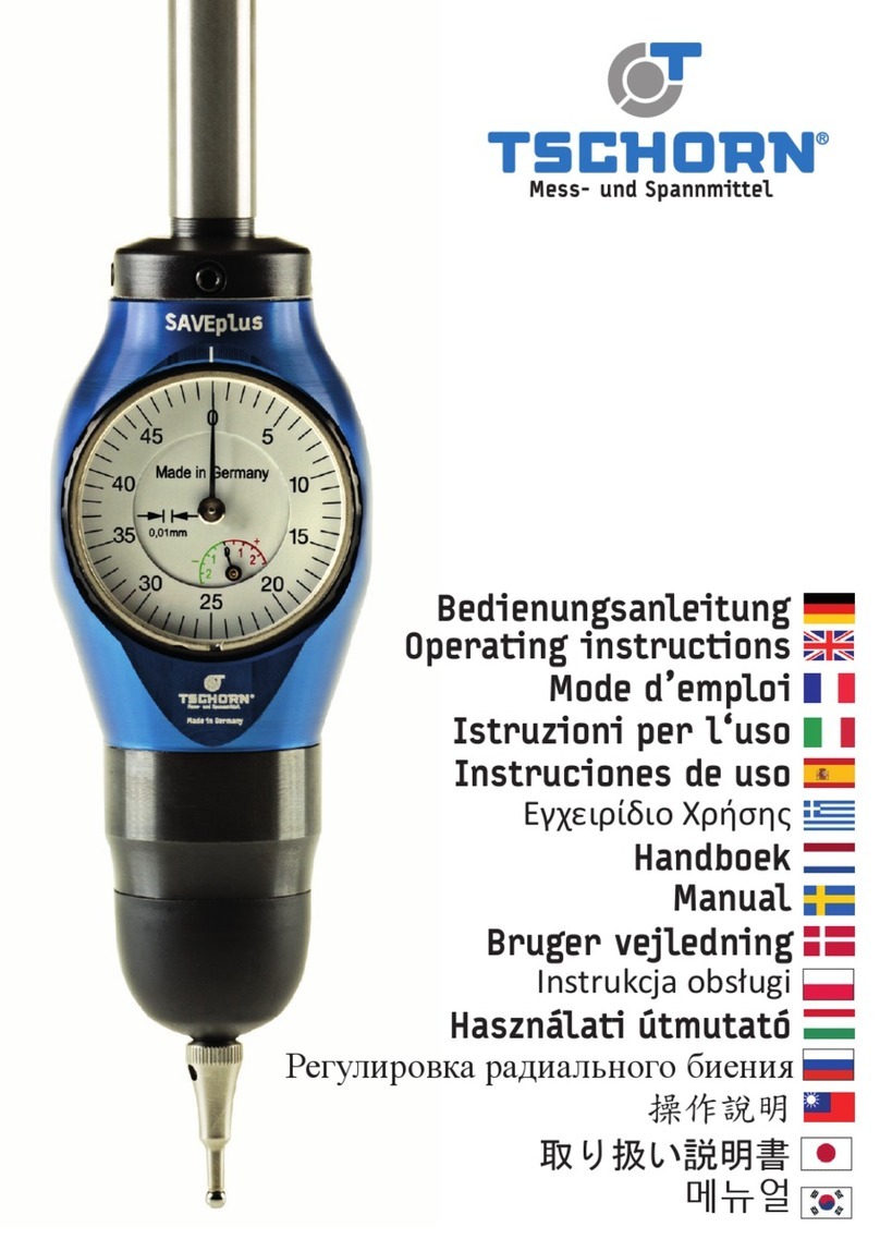
TSCHORN 3D Digital User manual

Download
Bedienungsanleitung 3D Digital
Operating instructions 3D Digital
Mode d’emploi 3D Digitale
Εγχειρίδιο Χρήσης 3D Digital
Handleiding 3D Digital
Bruksanvisning 3D Digital
Istruzioni per l‘uso 3D Digital
Instruciones de uso 3D Digital
Bruger vejledning 3D Digital
Instrukcja obsługi Cyfrowy czujnik 3D
Használati útmutató 3D Digital
Инструкция по эксплуатации 3D Цифровой тестер
操作說明 數位指示型3D探測頭
取り扱い説明書 3D テスタ 3Dデジタル
사용설명서 디지털 3D 테스터

Der 3D Taster ist ein Messmittel, das ausschließlich für das Antasten von
Werkstücken, oder -zeugen auf Bearbeitungszentren, Fräs- oder Drehmaschi-
nen verwendet werden soll.
WICHTIG:
Die aktuellste Version dieser Bedienungsanleitung nden Sie auf unserer
Website unter www.tschorn-gmbh.de oder mithilfe des unten stehenden QR-
Codes.
The 3D Tester is a measuring instrument which has exclusively be used for
the probing of work pieces in machining centres and milling machines.
IMPORTANT:
You can nd the latest version of this operating instructions on our website
www.tschorn-gmbh.de or with the QR-code below.
Le palpeur 3Dest un instrument de mesure qui doit être exclusivement uti-
lisé pour la palpage de la position des pièces sur les centres d‘usinage et
les fraiseuses.
IMPORTANT:
Vous trouverez la dernière version de ce mode d‘emploi sur notre site www.
tschorn-gmbh.de ou avec le QR-code ci-dessous.
Art.nr.
001D30012 3D Taster Digital mit Schaft Ø12
Download:
http://downloads.3dtaster.com/3DDigital_MAN.pdf
Bedienungsanleitung 3D Taster 3D Digital
Operating instructions 3D Tester 3D Digital
Mode d’emploi palpeur 3D Digital
1

Einstellschrauben
Adjustment screws
Vis de réglage
Messeinheit
measuring unit
unité de mesure
2 Sollbruchstellen
2 breaking points
2 Zone de rupture
Tastkugel
Probing ball
Bille
Schaft Ø12
Shank Ø12
Manche Ø12
Analoge Skala
Analogue scale
Echelle analogue
Digitale Skala
Digital scale
Echelle digitale
Tasteinsatz
Probe tip
Touche de palpage
Tasteinheit
Probing unit
L‘unité de palpage
Dichtung
Seal
Joint
Schlüsselbohrung
Key hole
Trous pour la clé
Batterieanzeige
Battery indicator
Indicateur de batterie
Status-LED
Status LED
LED d‘état
Beschreibung der Einzelteile
Description of component parts
Description des pièces détachées
2

Die Dichtung auf evtl. vorhandenes Vakuum
prüfen und gegebenenfalls entfernen.
Digitalanzeige prüfen:
Soll bei -1,500
Prüfen ob der Tasteinsatz sicher befestigt ist.
Prüfen des Rundlaufs in der Maschinenspindel.
(siehe Seite 4)
Bezugslänge des 3D Tasters ermitteln.
(siehe Seite 6)
1.
2.
3.
4.
5.
1.
2.
3.
4.
5.
1.
2.
3.
4.
5.
Check if the seal has got any existing vacuum
and remove it if necessary.
Check the digital display:
Should be at -1,500
Check if the probe tip is fastened securely.
Check the run-out in the spindle of the machine.
(see page 4)
Determine the reference length of the 3D Tester.
(see page 6)
Contrôler si le joint a un vide. Supprimer ce
vide si nécessaire.
Contrôler l‘indication digitale:
Doit être à -1,500
Contrôler si la pointe de palpage est xée
sûrement.
Contrôler la concentricité dans la broche de
la machine. (voir page 4)
Déterminer la longuer relative du palpeur 3D.
(voir page 6)
1.
2.
3.
3
Vor dem Gebrauch
Before use
Avant utilisation
Supprimez ce vide!

Taster in eine Werkzeugaufnahme einspannen.
Vor dem Rundlaufeinstellen, den Tasteinsatz händisch betätigen und in eine freie Ruheposition
bringen.
Messuhr an die Tastkugel anstellen. (siehe P1)
Den höchsten und den tiefsten Messpunkt nden. (siehe P3)
Mit den beiden Stellschrauben in Richtung der Messuhr, auf Mitte, einstellen. (siehe P2)
Wiederholen Sie den Vorgang so lange bis die gewünschte Rundlaufgenauigkeit erreicht ist.
Achten Sie darauf, dass am Ende alle 4 Stellschrauben mit maximal 2 Nm festgezogen sind.
Wenn der Rundlauf fertig eingestellt ist, den Tasteinsatz nicht mit der Hand betätigen.
1.
2.
3.
4.
5.
6.
7.
8.
Clamp the 3D-Tester into a tool holder.
Before adjusting the run-out, move the probe tip by hand and move it in to a free resting position.
Move the dial gauge to the probe sphere. (see P1)
Find the highest and lowest measuring point. (see P3)
Adjust the 3D-Tester with 2 adjustment screws to the centre position. (see P2)
Repeat the procedure until the desired run-out is achieved.
Make sure that all 4 adjustment screws are tightened with a maximum torque of 2
Newtonmeters.
As soon as the runout is adjusted manually, do not move the probe tip by hand anymore.
1.
2.
3.
4.
5.
6.
7.
8.
Fixer le 3D-Tester dans le porte-outil
Avant de régler la concentricité du 3D-Tester, bouger la touche de palpage à la main. Elle
doit retrouver naturellement sa position de repos.
Régler l’indicateur à levier sur la sphère de la touche (voir P1)
Rechercher le point de mesure mini et maxi (voir P3)
Régler le 3D-Tester, jusqu’à la position centrale grâce aux 2 vis de réglage qui sont dans
l’axe du comparateur à levier (voir P2)
Répéter l’opération jusqu’à l’obtention de la concentricité désirée.
Veillez bien à ce que les 4 vis de réglage soient serrées avec un couple maximum de 2Nm
Dès que la concentricité a été réglée, ne bougez plus la touche de palpage à la main.
1.
2.
3.
4.
5.
6.
7.
8.
- Stellschrauben (4 Stk.)
- Adjustable screws (4 pcs.)
- Vis de réglage (4 pc.)
P1 P2
P3
4
Justieren des Rundlaufs
Adjusting the radial runout
Réglage de la concentricité
WICHTIG - IMPORTANT - IMPORTANT:
Fühlhebelmessgerät verwenden! - Use a lever
gauge! - Utilisez un indicateur à levier!
KEINE Messuhr! KEINE Kamera! - No dial
gauge! No camera! - Pas de comparateur! Pas
d’appareils optiques!

Den 3D Taster in die Spindel einsetzen. Kühlmittelzufuhr und Spin-
del abschalten.
Bitte exakt senkrecht zum Werkstück antasten, sonst könnten
Messfehler entstehen.
Mit dem 3D Taster vorsichtig der Werkstückkante nähern, bis sich
die Balken der groben Analogskala abzubauen beginnen.
Mit dem Abbauen der Balken auf der Grobskala die Antastge-
schwindigkeit verringern.
Bei 0,25 mm schaltet die Analoganzeige von Grob- zu Feinskala um
und die LED leuchtet grün auf.
Langsam weitertasten bis der Zeiger und die Digitalanzeige 0,000
anzeigen.
In dieser Position steht die Spindelachse exakt über der Werk-
stückkante.
8. Hinweis: Ein Überfahren der Werkstückkante um bis zu 1,0 mm
(LED leuchtet ROT) ist problemlos. Nach 1,0 mm wird „ERR“ angezeigt
und es kommen mechanische Endanschläge, welche den Tasteinsatz
zum Bruch an der Sollbruchstelle führen, um den 3D Taster zu schüt-
zen.
Insert the 3D-Tester into the spindle. Cut-off the coolant supply
and turn off the spindle.
Please make sure that probing is exactly perpendicular. Otherwise,
measurement failures may occur.
Move the 3D Tester carefully to the edge of the workpiece until the
bars at the analogue scale start to decrease.
Reduce the probing speed while the bars decrease on the rough
scale.
At 0,25 mm the analogue scale changes from the rough scale to the
ne scale and the green LED lights up.
Carefully probe forwards until the indicator and the digital scale
show 0,000.
In this position, the symmetry axis of the spindle is exactly posi-
tioned to the workpiece edge.
1.
2.
3.
4.
5.
6.
7.
8. Note: It is not a problem to overpass the edge of the work piece
up to 1.0 mm (LED lights up in RED). After 1.0 mm, „ERR“ lights
up shown and there are mechanical limit stops which lead to the
breaking of the probe tip at the predetermined breaking point to
protect the 3D Tester.
Fixer le palpeur dans la broche. Couper l‘arrosage et la rotation
de la broche.
Assurez-vous de la parfaite position verticale du palpeur a n
d‘éviter toutes erreurs de mesure.
Approcher prudemment la touche du palpeur 3D du bord de la pièce
jusqu‘à ce que jusqu‘à ce que les barres de l‘échelle analogique
grossière commencent à se dégrader.
1.
2.
3.
4.
5.
6.
7.
8. Remarque: Un dépassement jusqu‘à 1.0 mm du bord de la pièce à mesurer (la LED
s‘allume en ROUGE) ne pose pas de problème. Après 1,0 mm, „ERR“ s‘af che la limite méca-
nique de la touche (zone de rupture) est atteinte a n de protéger le palpeur 3D.
1.
2.
3.
4.
5.
6.
7.
3.
5.
6.
8.
Réduisez la vitesse de sondage en enlevant les barres sur l‘échelle grossière.
À 0,25 mm, l‘af chage analogique passe de l‘échelle grossière à l‘échelle ne et la LED
s‘allume en vert.
Continuez lentement jusqu‘à ce que le pointeur et l‘af chage numérique indiquent 0,000.
Dans cette position, l‘axe de la broche est parfaitement aligné avec le bord de la pièce.
5
Antasten radial
Radial probing
Palpage radial

WICHTIG: Korrekte Messungen ertasten Sie nur in
Tastrichtung vorwärts! (rückwärts = Umkehrfehler)
Nach einem Überfahren der 0 - unbedingt zurück und
komplett freifahren
IMPORTANT: correct measurements are only possible
by probing forwards! (backwards = reverse fault)
After overcrossing 0 - move the probe back free
completely
IMPORTANT: Pour avoir une mesure correcte, tou-
jours mesurer en avançant dans le même sens (re-
tour en arrière = erreur de mesure)
Bezugslänge
reference length / Longueur de
référence
abzlg. 1,5 mm / less 1,5 mm / moins de 1,5 mm
Die Bezugslänge des 3D Tasters auf einem Voreinstellgerät
ermitteln. Dabei sind 1,5 mm für den Messweg des 3D Tasters
zu subtrahieren.
Den Taster in die Spindel einsetzen. Kühlmittelzufuhr und
Spindel abschalten.
Bitte exakt senkrecht zum Werkstück antasten, sonst könnten
Messfehler entstehen.
Antasten auf 0 wie bei Antasten radial beschrieben (Nr. 3-6).
Die Spindel steht nun in Höhe der ermittelten Bezugslänge
über dem Werkstück.
Hinweis: Der Hinweis Nr. 8 Überfahren gilt wie bei radial!
1.
2.
3.
4.
5.
Determine the reference length of the 3D Tester with a pre-
setting device. Please note that 1,5 mm must be subtracted
from this length.
Insert the 3D Tester into the spindle. Cut-off the coolant
supply and turn off the spindle.
Please make sure that the probing is exactly perpendicular.
Otherwise, measurement failures may occur.
Probe as described in probing radial (no. 3-6).
Now, the spindle is located at the height of the determined
reference length above the work piece.
Note: The noti cation no. 8 about overpassing is important
as in radial probing!
1.
2.
3.
4.
5.
La longueur de référence du palpeur est à déterminer avec
un appareil de préréglage. Il est nécessaire de soustraire
1.5 mm à cette longueur.
Fixer le palpeur dans la broche. Couper l‘arrosage et la ro-
tation de la broche.
Assurez-vous de la parfaite position verticale du palpeur
a n d‘éviter toutes erreurs de mesure.
Palpage à 0 comme décrit pour le palpage radial (no. 3-6).
Maintenant, la broche se trouve à la distance de référence
au dessus de la surface de la pièce.
Note: La note n° 8 dépassement s‘applique comme pour radial
1.
2.
3.
4.
5.
6
Antasten axial
Axial probing
Palpage axial

Den Taster in die Spindel einsetzen. Kühlmittelzufuhr und Spindel abschalten.
Mit dem 3D Taster vorsichtig der Werkstückkante nähern, bis sich die Analogskala sich zu
bewegen beginnt. Dann so lange weiter tasten bis die gewünschte Position erreicht ist.
Nun können Sie die Parallelität entlang Ihrer Werkstückkante abfahren. Dies ist in allen
Achsen X, Y oder Z möglich.
Insert the 3D Tester into the spindle. Cut-off the coolant supply and turn off the spindle.
Carefully approach the workpiece edge with the 3D Tester until the analogue scale starts
to move. Then keep probing until you reach the desired position.
Now you can start moving along the edge of the work piece to check parallelism in all
axis X, Y or Z.
1.
2.
3.
1.
2.
3.
Fixer le palpeur dans la broche. Couper l‘arrosage et la rotation de la broche.
Approchez avec précaution le bord de la pièce avec le palpeur jusqu‘à ce que l‘échelle
analogique commence à se déplacer. Maintenez ensuite la pression jusqu‘à ce que vous
atteigniez la position souhaitée.
Maintenant, vous pouvez commencer la mesure de la surface de la pièce. Cette mesure
est possible pour tous les axes (X, Y, ou Z).
1.
2.
3.
Hinweis: Ein Überfahren der Werkstückkante um bis zu 1,0 mm (LED leuchtet ROT) ist prob-
lemlos. Nach 1,0 mm wird „ERR“ angezeigt und es kommen mechanische Endanschläge, wel-
che den Tasteinsatz zum Bruch an der Sollbruchstelle führen, um den 3D Taster zu schützen.
Note: It is not a problem to overpass the edge of the work piece up to 1.0 mm (LED lights
up in RED). After 1.0 mm, „ERR“ lights up shown and there are mechanical limit stops which
lead to the breaking of the probe tip at the predetermined breaking point to protect the
3D Tester.
Remarque: Un dépassement jusqu‘à 1.0 mm du bord de la pièce à mesurer (la LED s‘allume
en ROUGE) ne pose pas de problème. Après 1,0 mm, „ERR“ s‘af che la limite mécanique de
la touche (zone de rupture) est atteinte a n de protéger le palpeur 3D.
7
Paralleles Abfahren X/Y/Z
Parallel running X/Y/Z
Palpage en parallèle X/Y/Z

Korrekte Funktion und Beweglichkeit der Tasteinheit
überprüfen.
Korrekte Funktion und Bewegung der Messeinheit
überprüfen.
Digitalanzeige prüfen:
Soll bei -1,500
Prüfen ob der Tasteinsatz sicher befestigt ist.
Prüfen und ggf. Justieren des Rundlaufs in der Ma-
schinenspindel (siehe Seite 3).
1.
2.
3.
4.
5.
Check correct function and movement of the
probing unit.
Check correct function and movement of the
measuring unit.
Check the digital display:
Should be at -1,500
Check if the probe tip is fastened securely.
Check and if necessary adjust the run-out in
the spindle of the machine (see page 3).
1.
2.
3.
4.
5.
Véri er le bon fonctionnement et la mobilité de
la touche de palpage.
Véri er le bon fonctionnement et la mobilité de
la touche de l‘unité de mesure.
Contrôler l‘indication digitale:
Doit être à -1,500
Contrôler si la pointe de palpage est xée
Contrôler la concentricité dans la broche de
la machine et la réajuster si nécessaire. (voir
page 3)
1.
2.
3.
4.
5.
1.
2.
3.
4.
Attention: if there is a fault, we offer our quick and non-
bureaucratic service.
If you want to, we can also make a quick-check with test
certi cate.
Attention: S‘il y a un problème de fonctionnement, nous
mettons à votre disposition un SAV ef cace et rapide.
Si vous le souhaitez, nous pouvons également faire un con-
trôle rapide du palpeur et délivrer un certi cat de con-
trôle.
8
Nach einem Crash
After a crash
Après un crash
ACHTUNG: Im Falle von Fehlfunktionen bieten wir Ihnen
schnellen und unbürokratischen Service.
Auf Wunsch führen wir auch einen Kurzcheck mit Werkszer-
ti kat für Sie durch.

Schrauben Sie die mitgelieferte Griffschraube (oder irgendeine andere Schraube M4) ein
(Abb. 1)
Öffnen Sie die Sicherungsschraube (Abb. 2)
Ziehen Sie den Batteriedeckel vorsichtig heraus (Abb. 3)
Entnehmen Sie die leere Batterie (Abb. 4 / Abb. 5)
Setzen Sie die neue Batterie ein (Abb. 6)
(Achten Sie dabei auf die richtige Polung: +-Pol nach oben)
Setzen Sie den Batteriedeckel vorsichtig ein (Abb. 7)
(Achten Sie dabei unbedingt darauf, die Dichtung nicht zu beschädigen und das Flachband-
kabel nicht einzuklemmen)
Drücken Sie den Batteriedeckel fest ein (Abb. 8)
Sichern Sie den Batteriedeckel mit der Sicherungsschraube (Abb. 2) und entnehmen an-
schliessend die „Griffschraube“ (Abb. 1)
1.
2.
3.
4.
5.
6.
7.
8.
1 2 3 4
8765
Screw in the supplied handle screw (or any other M4 screw) (see picture 1).
Open the locking screw (see picture 2).
Carefully pull out the battery cover (see picture 3).
Remove the empty battery (see picture 4 / 5).
Insert the new battery (see picture 6).
(Pay attention to the co viktor.leier@excor.de rrect polarity: + pole upwards).
Carefully insert the battery cover (see picture 7).
(Make absolutely sure not to damage the seal and not to pinch the ribbon cable).
Firmly push in the battery cover (see picture 8).
Fix the battery cover with the locking screw (see picture 2) and then remove the „handle
screw“ (see picture 1).
1.
2.
3.
4.
5.
6.
7.
8.
9
Batteriewechsel
Battery change
Changement de pile

100%
75%
50%
0%
25%
Visser la vis de poignée fournie (ou toute autre vis M4) (voir image 1).
Ouvrir la vis de blocage (voir image 2).
Retirez délicatement le couvercle de la batterie (voir image 3).
Retirer la batterie vide (voir image 4 / 5).
Insérer la nouvelle battérie (vpir image 6).
(Faites attention à la polarité correcte : pôle + vers le haut).
Insérez soigneusement le couvercle de la batterie (voir image 7).
(Assurez-vous absolument de ne pas endommager le joint et de ne pas pincer
le câble plat).
Poussez fermement le couvercle de la batterie (voir image 8).
Fixez le couvercle de la batterie avec la vis de verrouillage (voir image 2)
puis retirez la „vis de la poignée“ (voir image 1).
1.
2.
3.
4.
5.
6.
7.
8.
10
Batterieanzeige
Battery status
Status de pile

Die Dichtung öffnen und aus der Rille ziehen.
Die Dichtung nach oben schieben und abnehmen.
Den Tasteinsatz von Hand herausschrauben (evtl. kann er auch mit Hilfe des mitgeliefer-
ten Schlüssels gelockert werden).
Den Tasteinsatz komplett heraus schrauben. Achten Sie dabei darauf, den Gewindestift
mit heraus zu schrauben.
Neuen Tasteinsatz einschrauben und mit Hilfe des Schlüssels festdrehen.
Die Dichtung über den Tasteinsatz ziehen.
Dichtung über die Tasteinheit schieben und in die Rille verschließen.
1.
2.
3.
4.
5.
6.
7.
Open the seal and remove out of the groove.
Move up the seal and put it off.
Unscrew the probe tip manually (if needed, the probe tip can be released with the de-
livered key).
Unscrew the probe tip entirely and make sure that the threaded pin is unscrewed as well.
Screw in the new probe tip and tighten it with the key.
Put the seal onto the probe tip.
Slip the seal over the probing unit and close it into the groove.
1.
2.
3.
4.
5.
6.
7.
Décoller le joint et le sortir de sa rainure.
Glisser le joint vers le haut et le retirer.
Dévisser à la main la touche de palpage (si nécessaire, la touche du palpeur peut être
débloquée avec la clé.
Dévisser complètement la touche de palpage. Veiller également à dévisser la tige letée.
Visser fermement à la main la nouvelle touche de palpage.
En ler le joint sur la touche de palpage.
En ler le joint sur l‘unité de palpage et l‘insérer dans la rainure.
1.
2.
3.
4.
5.
6.
7.
1. 2. 2. 3.
4. 5. 6.
ACHTUNG: Bitte Rundlauf überprüfen!
ATTENTION: Please check run-out!
ATTENTION: contrôlez, s‘il vous plaît, la concentricité!
7.
11
Tasteinsatz / Dichtung auswechseln
Replace probe tip / seal
Remplacement de la touche de palpage / joint

Schützen Sie Ihren 3D Taster grundsätzlich vor harten Stößen und
bewahren Sie den 3D-Taster im mitgelieferten Etui auf.
Mit dem Öffnen des Geräts verlieren Sie Anspruch auf Garantie.
Zur Reinigung bitte nur lösungsfreie Reinigungsmittel verwenden.
Ein verlängerter Tasteinsatz ist als Zubehör lieferbar.
Protect your 3D Tester against strong shocks and keep the
3D Tester in the supplied case.
Warranty will be lost if you open the 3D-Tester.
For cleaning just use solvent-free detergents.
A longer probe tip is available as accessory.
Toujours protéger votre palpeur 3D contre les chocs et gardez le
palpeur 3D dans le boîtier fourni.
L‘ouverture de l‘appareil annule tout droit à garantie.
Utiliser exclusivement un détergent sans solvant pour le nettoyage.
Une touche de palpage longue peut être livrée en accessoire.
Bei technischen Schwierigkeiten sind wir schnell und zuverlässig für Sie da.
In case of technical dif culties, we will help you immediately and reliably.
Nous sommes toujours à votre disposition en cas de dif cultés techniques.
12
Hinweise & Service
Noti cations & Service
Avertissements & Service

Il 3D-Tester è uno strumento di misura che viene utilizzato esclusivamente
per il rilevamento di pezzi da lavorare in centri di lavoro e fresatrici torni.
È possibile trovare l‘ultima versione del manuale di istruzioni sul nostro
sito www.tschorn-gmbh.de o con il QR-code sotto.
El 3D taster es un aparato de medición que debe utilizarse, solamente para
buscar la posición de las piezas en centros de macanizado y fresadoras.
La última versión de este manual de instrucciones se puede encontrar en
nuestro sitio web en www.tschorn-gmbh.de o mediante el siguiente código
QR.
Το 3D-Tester είναι ένα όργανο μέτρησης το οποίο χρησιμοποιείται αποκλειστικά για
το σετάρισμα των τεμμαχίων σε κάθετα κέντρα κατεργασίας (CNC).
Θα βρείτε την τελευταία έκδοση αυτών των οδηγιών χρήσης στην ιστοσελίδα μας
www.tschorn-gmbh.de ή σκανάροντας τον κωδικό QR παρακάτω.
Art.nr.
001D30012 3D Taster Digital mit Schaft Ø12
Download:
http://downloads.3dtaster.com/3DDigital_MAN.pdf
13
Istruzioni per l‘uso
Instruciones de uso
Εγχειρίδιο Χρήσης

Viti di regolazione
Tornillos de ajuste
Βίδες Ρύθμισης
Unità di misura
Unidad de medición
Μονάδα Μέτρησης
Punto di rottura
Punto de rotura
Σημείο αποκοπής
Sfera di Tastatura
Bola de palpador
Μπίλια μέτρησης - επαφής
Attacco ø12
Mango diámetro Ø 12
Στέλεχος Φ12
Scala analogica
Escala analógica
Αναλογική κλίμακα
Scala digitale
Escala digital
Ψηφιακή κλίμακα
Puntalino
Palpador
Ακίδα μέτρησης - επαφής
Unità di Tastatura
Palpador
Μονάδα επαφής
Cuf a di protezione
Protector
Ασφάλεια
Foro per Chiave
Agujero para la llave
οπή κλειδιού σύσφιξης
Livello batteria
Indicador carga
de bateria
Δείκτης Μπαταρίας
LED di posizione
Estado-LED
����τάσταση-LED
14
Descrizione dei componenti
Descripcion de los componentes
Περιγραφή των μερών του 3D-Tester

Controllare se ci sia del vuoto all‘interno del sigillo,
rimuoverlo se necessario.
Controllare il display digitale:
Dovrebbe essere a -1.500.
Controllare che il puntalino sia ssato saldamente.
Controllare il runout nel mandrino della macchina (vedi
pagina 16)
Determinare la lunghezza di riferimento del 3D Tester
(vedi pagina 18)
1.
2.
3.
4.
5.
1.
2.
3.
4.
5.
1.
2.
3.
4.
5.
Comprobar que el protector este correcto.
Comprobar el display digital:
Debe estar a -1,500
Comprobar que el palpador está bien sujeto.
Comprobar la concéntricidad con el cabezal de la máquina
(ver pagina 16)
Determinar la lóngitud del palpador.
(ver pagina 18)
Ελέγξτε εάν η ασφάλεια η ασφάλεια έχει κάποια
συμπίεση και απελευθερώστε την.
Ελέγξετε την ψηφιακή ένδειξη Πρέπει να είναι στο
1,5002
Ελέγξτε αν η ακίδα επαφής έχει σφίξει ασφαλώς.
Ελέγξτε το run-out στην άτρακτο της μηχανής.
(βλέπε σελίδα 16)
Καθορίστε το μήκος αναφοράς του 3D-Tester.
(βλέπε σελίδα 18)
1.
Vuoto?
Tiene algun vacio?
Υπάρχει αέρας ;
Eliminare il vuoto!
Eliminar el vacio!
Αφαιρέστε τον αέρα
2.
3.
15
Prima dell‘uso
Antes de usar
Πριν τη χρήση

Montare il tastatore in macchina tramite idoneo mandrino. Prima di regolare l‘eccentricità,
muovere il puntalino di tastatura a mano e rilasciarlo in posizione centrale. Appoggiare
un comparatore (1) perpendicolarmente contro la sfera del puntalino del centratore 3D (2)
senza creare pressione, ruotare lentamente il tastatore e controllare la concentricità, in
caso di errore agire sui 4 grani di centraggio allentando i grani posizionati nel lato dove
il comparatore rileva l’errore per eccesso e avvitando i grani posizionati sul lato dove il
comparatore rileva l’errore per difetto sino al centraggio del tastatore.
Attenzione al termine tutte le viti devono essere ssate con la torsione massima di 2 New-
ton metro. Non appena viene regolata la centratura, non muovere più la punta della sonda.
Amarrar el 3D Taster en el portapinzas.
Antes de ajustar la concéntricidad del 3D Taster, comprobar manualmente que el palpador, debe
volver a su posición original de reposo.
Colocar el palpador del 3D, en la punta del reloj (ver P1).
Buscar los puntos, de medida mínimo y máximo (ver P3).
Ajustar el 3D Taster en la posición central, con los tornillos que están en el eje del
comparador (ver P3).
Repetir la operación hasta obtener la concentricidad deseda, en el otro eje.
Comprobar que los 4 tornillos estén bien amarrados - máximo 2 Newtons por metro.
Una vez, que la concentricidad esta correcta, no tocar el palpador manualmente.
1.
2.
3.
4.
5.
6.
7.
8.
Σφίξτε το 3D-Tester σε μία μέγγενη συγκράτησης.
Πριν ρυθμίσετε την εκκεντρότητα, κουνήστε με το χέρι την μύτη του οργάνου.
Μετακινήστε το Ρολόι μέτρησης προς την μπίλια επαφής.
Βρείτε το μέγιστο και το ελάχιστο σημείο μέτρησης.
Ρυθμίστε το 3D-Tester με τις 2 βίδες ρύθμισης στην θέση του απόλυτου κέντρου. Επαναλάβετε την
διαδικασία μέχρι να ελαχιστοποιήσετε την εκεντρότητα,
Βεβαιωθήτε ότι όλες οι βίδες έχουν σφίξει με την μέγιστη δύναμη που είναι 2 Νιουτόμετρα.
Μόλις η εκκεντρότητα ρυθμιστεί, μην κινήσετε άλλο την μύτη με το χέρι.
1.
2.
3.
4.
5.
6.
7.
8.
- Viti di registrazione (4 pz.)
- Tornillo de reglaje (4 piezas)
- Βίδες Ρύθμισης (4 τεμ.)
P1 P2
P3
Importante - IMPORTANT - Σημαντικό:
Utilizzare un Pulpitaster! - ¡utilice el dial prueba!
- Χρησιμοποιείστε ρολόι ακίδος (κεντραρίσματος)! -
Assolutamente non usare un comparatore o una
videocamera! - ¡Sin comparador de cuadrante! ¡Sin
cámara! - Όχι ρολόι γράφτη! Όχι κάμερα!
16
Centraggio del 3D Taster
Ajuste de la concentricidad
Ρύθμιση εκκεντρότητας περιστροφής

Inserire il 3D-Tester nel mandrino. Chiudere il refrigerante e man-
drino fermo
Assicurarsi che la sonda sia perpendicolare. In caso contrario, pot-
rebbero vericarsi errori di misurazione.
Spostare con cautela il 3D-Tester verso il bordo del pezzo no a
quando le barre della scala analogica iniziano a diminuire.
Ridurre la velocità di tastatura mentre le barre diminuiscono sulla
scala approssimativa.
A 0,25 mm la scala analogica passa dalla scala grossolana alla scala
ne e il LED verde si accende.
Prosegui con cautela in avanti nché l‘indicatore e la scala digitale
non visualizzano 0,000.
In questa posizione, l‘asse di simmetria del mandrino è posizionato
esattamente sul bordo del pezzo. 3.
5.
6.
8.
8. Nota: non è un problema superare il bordo del pezzo no a 1,0 mm
(il LED si accende in ROSSO). Dopo 1,0 mm, si accende la scritta „ERR“ e
sono presenti arresti meccanici di ne corsa che portano alla rottura
del puntalino della sonda nel punto di rottura predeterminato per
proteggere il tester 3D.
1.
2.
3.
4.
5.
6.
7.
Colocar el 3D Taster en el cabezal de la máquina.
Cerrar el paso del refrigerante, no girar el cabezal de la máquina.
Comprobar que el 3D Taster esté posicionado correctamente, en po-
sición vertical, de otra forma, puede haber errores en la medición.
Aproximar poco a poco, la punta del palpador a la pieza, hasta que
las agujas del comparador empiecen a moverse.
Reducir la velocidad del palpador.
Cuando llegue a 0.25 mm, la escala del reloj, pasa de lectura 1.5 mm
a lectura 0.25 mm, para mayor precisión y se enciende la luz verde.
Continuar lentamente, hasta que le reloj indique 0,000.
En esta posición, el eje está perfectamente alineado con el borde
de la pieza.
8. Nota: No hay problema alguno si el eje de la pieza, sobrepasa 1 mm
‚error‘, empieza el limite mecánico (zona de rotura), para proteger el
3D Taster.
1.
2.
3.
4.
5.
6.
7.
Τοποθετήστε τον 3D Tester στον άξονα. Κόψτε την παροχή ψυκτικού υγρού
και κλείστε τον άξονα.
Παρακαλώ βεβαιωθείτε ότι η ανίχνευση είναι ακριβώς κάθετη. Διαφορετικά
υπάρχει περίπτωση λάθους μέτρησης.
Μετακινήστε το 3D Tester προσεκτικά στην άκρη του τεμαχίου μέχρι οι
ράβδοι στην αναλογική κλίμακα ν‘ αρχίσουν να μειώνονται.
Μειώστε την ταχτυτητα ανίχνευσης μέχρι οι ράβδοι να μειωθούν στην
πρόχειρη κλίμακα.
Στα 0,25mm η αναλογική κλίμακα αλλάζει από πρόχειρη κλίμακα στην λεπτή
κλίμακα και το πράσινο LED ανάβει.
Ανιχνεύεστε προσεκτικά προς τα εμπρός εως ότου η ένδειξη και η ψηφιακή
κλίμακα δείξουν 0,000.
Σε αυτή την θέση ο άξονας συμμετρίας του άξονα είναι ακριβώς
τοποθετημένος στην άκρη του τεμαχίου.
8. Σημείωση: Δεν είναι πρόβλημα η υπέρβαση των άκρων του τεμαχίου έως 1,00 mm. (H λυχνία LED
ανάβει κόκκινο). Μτετά από 1mm, „ERR“ εμφανίζεται και υπάρχουν μηχανικά όρια που οδηγούν στο
σπάσιμο του άκρου του αισθητήρα στο προκαθορισμένο σημείο θραύσηςγια την προστασία του 3D
Tester.
1.
2.
3.
4.
5.
6.
7.
17
Misurazione radiale
Ajuste radial
Μέτρηση οριζόντιων αξόνων

Determinare la lunghezza di riferimento con un pre setting.
Da ricordare il fatto che 1,5 mm devono essere sottratti dalla
lunghezza.
Montare il tastatore in macchina tramite un idoneo mandri-
no, attenzione a non far ruotare per nessuna ragione il man-
drino macchina e spegnere la lubri cazione.
Assicurarsi che il puntalino sia perfettamente perpendicola-
re. In caso contrario potrebbero veri carsi errori di misura.
Esegui la tastatura come descritto in Tastatura radiale (n. 3-6).
Ora il mandrino macchina si trova esattamente sopra il pezzo
all‘altezza pre determinata dalla lunghezza di riferimento.
1.
2.
3.
4.
5.
Nota: l‘avvertenza n. 8 sul superamento è importante come per
la tastatura radiale!
Determinar la longitud del palpador con un aparato de prereglaje.
Es necesario restar 1,50 mm dee sta logitud (radio de la bola).
Colocar el 3D Taster en el cabezal. Quitar la taladrina y parar
la máquina.
Comprobar que el palpador está perpendicular, para evitar
errores de medición.
LLegar al punto 0, como se indica en la pag 3-6.
Ahora, el palpador está a la distancia de referencia encima
de la pieza a mecanizar.
1.
2.
3.
4.
5.
Nota: la indicación no. 8 de sobremedida se aplica como para
medición radial.
Προσδιορίστε το μήκος του 3D-Tester με μία συσκευή
καλυμπραρίσματος. Σημειώστε ότι 1,5 χιλιοστό πρέπει να αφαιρεθεί
από το τελικό μήκος.
Τοποθετήστε το 3D-Tester στην κεφαλή περιστροφής.
Απενεργοποιήστε την ψύξη και την περιστροφή της κεφαλής.
Βεβαιωθείτε ότι η μέτρηση γίνεται σε απόλυτη κάθετη θέση. Σε
αντίθετη περίπτωση θα εμφανιστούν λάθη κατά την μέτρηση.
Ανιχνεύεστε όπως περιγράφεται στην ακτινική ανίχνευση (no.3-6)
Τώρα, η κεφαλή βρίσκεται στο προσδιορισμένο ύψος από το
δοκίμιο.
1.
2.
3.
4.
5.
Σημείωση: η επισήμανση με αριθμό 8 για την υπέρβαση είναι
σημαντική όπως και στην ακτινική ανίχνευση!
IMPORTANTE: le misure corrette sono possibili solo
tastando in avanti! (all‘indietro = errore inverso)
Se si supera lo 0 ritornare e staccarsi dal bordo,
dopo riprendere la tastatura.
IMPORTANTE: Para tener una correcta medición, mover
el 3D Taster siempre en la misma dirección (siempre
tiene que sar hacia adelante, sentido horario. El des-
plazamiento en sentido contrario, nos dará error, y
deberemos de comenzar la medición desde el principio.
ΣΗΜΑΝΤΙΚΟ: οι σωστές μετρήσεις είναι δυνατές μόνο με
ανίχνευση προς τα εμπρός! (προς τα πίσω = αντίστροφη
βλάβη)
Αφού ξεπεράσει 0 - μετακινήστε τον αισθητήρα προς τα
πίσω εντελώς ελεύθερα. ΣΗΜΑΝΤΙΚΟ: οι σωστές μετρήσεις
είναι δυνατές μόνο με ανίχνευση προς τα εμπρός! (προς τα
πίσω = αντίστροφη βλάβη)
Αφού ξεπεράσει 0 - μετακινήστε τον αισθητήρα προς τα
πίσω εντελώς ελεύθερα.
Lunghezza di riferimento/
referencia de la longitud / Μήκος αναφοράς
meno 1,5 mm / -1.50 mm (radio de la bola) /
λιγότερο από 1,5 mm
Lunghezza di riferimento/
18
Misurazione assiale: Asse X
Ajuste axial
Μέτρηση κάθετων αξόνων

Inserire il 3D-Tester nel mandrino. Spegnere il refrigerante e il mandrino deve essere
fermo.
Avvicinarsi con cautela al bordo del pezzo con il 3D-Tester nché la scala analogica non
inizia a muoversi. Quindi continuare a tastare no a raggiungere la posizione desiderata.
Ora è possibile iniziare a muoversi lungo il bordo del pezzo per controllare il paralle-
lismo nei tre assi X, Y o Z.
Nota: non è un problema superare il bordo del pezzo no a 1,0 mm (il LED si accende in
ROSSO). Dopo 1,0 mm, si accende la scritta „ERR“ e sono presenti arresti meccanici di ne
corsa che portano alla rottura del puntalino della sonda nel punto di rottura predetermi-
nato per proteggere il tester 3D.
Colocar el palpador en el cabezal. Cerrar el paso de refrigerante y parar el cabezal.
Aproximar con precisión, hasta el borde de la pieza, hasta que la aguja, comience a mo-
verse. Mantener la presión, hasta alcanzar la posición deseada.
Ahora se puede empezar la medición de la supercie de la pieza, para comprobar el
paralelismo en X-Y-Z.over por el eje para comprobar los ejes X,Y y Z.
1.
2.
3.
Nota: No es problema, sobrepasar en 1 mm, el rango de medida (Led roja). Después de este
límite, pasamos a la zona („ERR“), en la cual actuan los límites mecánicos, con el riesgo
de rotura del palpador, para proteger el 3D Taster.
Σημείωση: Δεν είναι πρόβλημα η υπέρβαση των άκρων του τεμαχίου έως 1,00 mm. (H λυχνία LED
ανάβει κόκκινο). Μτετά από 1mm, το „ERR“ εμφανίζεται και υπάρχουν μηχανικά όρια που οδηγούν
στο σπάσιμο του άκρου του αισθητήρα στο προκαθορισμένο σημείο θραύσηςγια την προστασία του
3D Tester.
1.
2.
3.
IΤοποθετήστε το 3-D tester στην άτρακτο. Διακόψτε την παροχή ψυκτικού και απενεργοποιήστε την
άτρακτο.
Προσεγγίστε προσεκτικά την άκρη του τεμαχίου εργασίας με το 3D Tester μέχρι να αρχίσει να κινείτε η
αναλογική κλίμακα. Στη συνέχειασυνεχίστε να κάνετε ανίχνευση μέχρι να φτάσετε στην επιθυμητή θέση.
Τώρα μπορείτε να αρχίσετε την κίνηση κατά μήκος του δοκιμίου για να ελέγξετε την παραλληλότητα
σε όλους τους άξονες Χ, Υ ή Ζ.
1.
2.
3.
19
Controllo del parallelismo in x/y/z
Medición en paralelo, X/Y/Z
Παράλληλη λειτουργία Χ / Υ / Ζ
This manual suits for next models
1
Table of contents
Other TSCHORN Measuring Instrument manuals
