Thies CLIMA 4.387 Series User manual

THE WORLD OF WEATHER DATA - THE WORLD OF WEATHER DATA - THE WORLD OF WEATHER DATA
Instruction for Use
021546/12/17
Ultrasonic Anemometer 2D compact
4.387x.xx.xxx
from software version V3.11 Status: 10/2017
ADOLF THIES GmbH & Co. KG
Hauptstraße 76 37083 Göttingen Germany
Box 3536 + 3541 37025 Göttingen
Phone +49 551 79001-0 Fax +49 551 79001-65
www.thiesclima.com inf[email protected]
2 - 68 021546/12/17
Safety Instructions
•Before operating with or at the device/product, read through the operating instructions.
This manual contains instructions, which should be followed on mounting, start-up, and operation.
A non-observance might cause:
- failure of important functions
- Endangering of persons by electrical or mechanic effect
- Damages at objects
•Mounting, electrical connection and wiring of the device/product must be carried out only by a qualified
technician who is familiar with and observes the engineering regulations, provisions and standards applicable
in each case.
•Repairs and maintenance may only be carried out by trained staff or Adolf Thies GmbH & Co. KG. Only
components and spare parts supplied and/or recommended by Adolf Thies GmbH & Co. KG should be used
for repairs.
•Electrical devices/products must be mounted and wired only in voltage-free state.
•Adolf Thies GmbH & Co KG guarantees proper functioning of the device/products provided that no
modifications have been made to the mechanics, electronics or software, and that the following points are
observed:
•All information, warnings and instructions for use included in these operating instructions must be taken into
account and observed as this is essential to ensure trouble-free operation and a safe condition of the
measuring system / device / product.
•The device / product is designed for a specific application as described in these operating instructions.
•The device / product should be operated with the accessories and consumables supplied and/or
recommended by Adolf Thies GmbH & Co KG .
•Recommendation: As it is possible that each measuring system / device / product under certain conditions,
and in rare cases, may also output erroneous measuring values, it is recommended to use redundant systems
with plausibility checks with security-relevant applications.
Environment
•As a longstanding manufacturer of sensors Adolf Thies GmbH & Co KG is committed to the
objectives of environmental protection and is therefore willing to take back all supplied
products governed by the provisions of "ElektroG" (German Electrical and Electronic
Equipment Act) and to perform environmentally compatible disposal and recycling. We are
prepared to take back all Thies products concerned free of charge if returned to Thies by our
customers carriage-paid.
•Make sure you retain packaging for storage or transport of products. Should packaging
however no longer be required, arrange for recycling as the packaging materials are
designed to be recycled.
Documentation
•© Copyright Adolf Thies GmbH & Co KG, Göttingen / Germany
•Although this operating instruction has been drawn up with due care, Adolf Thies GmbH & Co KG can accept
no liability whatsoever for any technical and typographical errors or omissions in this document that might
remain.
•We can accept no liability whatsoever for any losses arising from the information contained in this document.
•Subject to modification in terms of content.
•The device / product should not be passed on without the/these operating instructions.
Explanation of Symbols
•Warning for hot surface

3 - 68 021546/12/17
Patent Protection
This instrument is patent-protected
Patent No.: EP 1 448 966 B1
Patent No.: US 7,149,151 B2
Operating Instructions
These operating instructions describe all possible applications and settings of the instrument. The
Ultrasonic Anemometer 2D compact is factory-set.
Identification for the factory setting derives from the order No. and the respective "Factory Setting"
Order number and Setting
see supplementary sheet
"Factory Setting"
With these detailed operating instructions and via the serial interface of the Ultrasonic Anemometer
2D compact it is possible for the user to adapt the factory-settings to his own requirements.
Shipment
1 x Ultrasonic Anemometer Compact
1 x Operating Instructions
1 x Supplementary Sheet: Factory Setting
1 x Factory certification

4 - 68 021546/12/17
Contents
1Models available............................................................................................................6
2Application.....................................................................................................................7
3Mode of Operation.........................................................................................................8
3.1 Measuring Principle: Wind velocity and direction................................................................8
3.2 Measuring principle: Acoustic virtual temperature...............................................................9
3.3 Measuring principle: Air pressure (optional)........................................................................9
3.4 Heating...............................................................................................................................9
4Preparation for operation.............................................................................................10
4.1 Selection of installation site...............................................................................................10
4.2 Installation of Anemometer...............................................................................................11
4.3 Alignment to north / Positioning ........................................................................................12
4.4 Electrical Installation for Ultrasonic Anemometer..............................................................13
4.4.1 Cables, Cable preparation, Connector Installation......................................................14
4.4.2 Connector Pin Assignment (Examples of Function)....................................................15
5Maintenance................................................................................................................16
6Calibration....................................................................................................................16
7Warranty......................................................................................................................16
8Functional description..................................................................................................17
8.1 Serial communication .......................................................................................................17
8.1.1 Duplex mode..............................................................................................................17
8.1.2 Response Delay.........................................................................................................18
8.1.3 General telegram structure for the Thies Interpreter...................................................18
8.1.4 Saving of the ULTRASONIC Parameters..................................................................19
8.1.5 Return values of ULTRASONIC.................................................................................19
8.1.6 Access Mode..............................................................................................................20
8.1.7 Baud rate ...................................................................................................................21
8.1.8 Instrument ID..............................................................................................................21
8.1.9 Bus mode...................................................................................................................22
8.2Analogue outputs..............................................................................................................22
8.2.1 Scaling of analogue wind velocity...............................................................................23
8.2.2 Correction to North.....................................................................................................23
8.3Instantaneous values and output of raw measured values................................................23
8.3.1 Averaging...................................................................................................................23
8.4 Serial Data Output............................................................................................................24
8.4.1 Data Query.................................................................................................................24
8.4.2 Independent telegram output......................................................................................25
8.4.3 Fixed telegram formats...............................................................................................25
8.4.4 Generation of check sum ...........................................................................................26
8.4.5 Status information......................................................................................................26
8.5 Behaviour of Instrument under extreme Conditions of Measurement Value Acquisition....29

5 - 68 021546/12/17
8.6 Behaviour in Case of Error................................................................................................29
8.6.1 Behaviour of analogue outputs...................................................................................29
8.6.2 Behaviour of telegram output .....................................................................................29
8.7 Output of all system parameters.......................................................................................30
8.8 Enquiry about software version.........................................................................................30
8.9 Forcing a restart ...............................................................................................................30
8.10 Energy-saving mode.........................................................................................................30
8.11 Plausibility ........................................................................................................................30
8.12 Online help.......................................................................................................................31
9Configuration of ultrasonic anemometer by customer..................................................31
10 Thies Command Interpreter.........................................................................................32
10.1 List of Commands Thies Interpreter..................................................................................32
10.2 Command and description................................................................................................33
11 MODBUS RTU Command Interpreter..........................................................................49
11.1 MODBUS RTU Telegram Construction.............................................................................49
11.2 Command Description......................................................................................................50
11.3 Measuring values (Input Register)....................................................................................50
11.4 Commands (Holding Register)..........................................................................................53
12 Appendix 1 Predefined data telegrams........................................................................54
12.1 Telegram 1 VD ................................................................................................................54
12.2 Telegram 2 VDT ..............................................................................................................55
12.3 Telegram 3 VD2 ..............................................................................................................56
12.4 Telegram 00004 NMEA ...................................................................................................57
12.5 Telegram 7 Vx, Vy, VT.....................................................................................................58
12.6 Telegram 8 VDM .............................................................................................................59
12.7 Telegram 9 VDPM...........................................................................................................60
12.8 Telegram 11 PBT .............................................................................................................62
12.9 Telegram 12 Scientific Telegram .....................................................................................62
13 Technical Data.............................................................................................................63
14 Dimension Drawing......................................................................................................65
15 Accessories (available as optional features)................................................................66
16 EC-Declaration of Conformity......................................................................................67
Figure
Figure 1: Connector installation..................................................................................................... 14
Table
Table 1: Restrictions in full and half duplex mode.......................................................................... 18
Table 2: Access key for different command levels......................................................................... 20
Table 3: Config. of analogue outputs WV/RXD- and WD/RXD+ with parameters AO a. SC........... 22
Table 4: List of predefined data telegrams..................................................................................... 25
Table 5: Adjustment of averaging periods with parameter AV........................................................ 34
Table 6: List of baud rates with telegram BR................................................................................. 35
Table 7: Conversion factors between different wind velocities....................................................... 42

6 - 68 021546/12/17
Table 8 : MODBUS Frame............................................................................................................. 49
Table 9 : MODBUS Exceptions ..................................................................................................... 49
Table 10 : MODBUS Input Register............................................................................................... 52
Table 11 : List of commands MODBUS RTU Interpreter................................................................ 53
1 Models available
Description
Article- No. *
Parameter
Output / Interface/ Equipment
US-Anemometer 2D
compact
4.3875.0X.XXX Wind velocity
Wind direction
Virtual temperature
- 0 ... 20 mA / 0 ... 10 V
(4 ... 20 mA / 2 ... 10V)
- RS485/ 422
- 8 pole plug connection
- heating for:
base plate
cover plate
Sensor receiving sockets
US-transducer
- hard-anodized housing
4.3875.1X.XXX
Wind velocity
Wind direction
Virtual temperature
- w/o heating for US-transducer
4.3875.2X.XXX Wind velocity
Wind direction
Virtual temperature
Barometric air pressure
- with optionally integrated
Baro-transmitter
4.3875.XX.XXX Depending on article nol. Configuration concerning
- outputs
- data telegrams
- scaling
- etc.
* The complete article-no. results from the arranged equipment and configuration.

7 - 68 021546/12/17
2 Application
The Ultrasonic Anemometer 2D compact is used to detect the horizontal components of wind
velocity and wind direction in 2 dimensions in particular sturdy design. In addition, the virtual
temperature is measured.
Optionally, the measurement of the “atmospheric air pressure (absolute)” is possible.
The instrument is especially suited for application in the fields of
•Industrial automation
•Regenerative power generation (wind power plants)
•Building automation
•Traffic engineering/ control system
•maritime and offshore applications
Due to the measuring principle the instrument is ideal for inertia-free measurement of gusts and peak
values.
Output of the measured values can be either digital and / or analogue.
- analogue, as a standard signal or / and in
- ASCII (THIES format) or
- binary (MODBUS RTU protocol)
The analogue and digital interfaces operate in electrical isolation from supply and housing potential.
Thus, there is no galvanic connection, which might result in a superposition of interference currents
or voltages on the output signals.
Digital output: An RS485/422 is available for serial communication. It can be operated in full or half-
duplex mode. For the output of measured values there are a number of pre-defined telegrams (e.g.
WV, WD, WVx, WVy, NMEA etc.).
A MODBUS RTU protocol is additionally implemented for extended standardised communication.
The device can be switched to MODBUS-RTU mode with the relevant command.
Analogue outputs: Wind velocity and direction are output either as a power or voltage signal.
Individual measuring range scaling of the analogue outputs for WV and WD are selectable.
The serial or analogue output of the data is either as an instantaneous value or as a gliding mean.
The instrument is automatically heated if necessary with critical ambient temperatures. This also
ensures functionality with snowfall and sleet and minimises the risk of malfunctions due to icing-up.
Thanks to the optional integrated ultrasonic converter heating the instrument is especially suited to
cope with difficult icing conditions in high mountains and in other critical locations.
The instrument is equipped with a battery-buffered real-time-clock, so that the data telegrams are
output with date- and time-stamp.

8 - 68 021546/12/17
3 Mode of Operation
The Ultrasonic Anemometer 2D compact consists of 4 ultrasonic transformers, in pairs of two
facing each other at a distance of 200 mm. The two resulting measurement paths are vertical to each
other. The transformers function both as acoustic transmitters and receivers.
The electronic control system is used to select the respective measurement path and its measuring
direction. When a measurement starts, a sequence of 4 individual measurements is performed in all
4 directions of the measurement paths in a basis measuring cycle of one msec.
The measuring directions (sound propagation directions) rotate clockwise.
The mean values are worked out from the 4 individual measurements of the path directions and
used to make further calculations.
The time required for a measuring sequence is exactly 10.0 ms (8 ms measuring sequence +2 ms
analysis) at the maximum measuring speed.
3.1 Measuring Principle: Wind velocity and direction
The speed of propagation of the sound in calm air is superposed by the velocity components of an
airflow in the direction of the wind.
A wind velocity component in the propagation direction of the sound supports the speed of
propagation; i.e. it increases it while a wind velocity component against the propagation direction
reduces the speed of propagation.
The propagation speed resulting from superposition leads to different propagation times of the
sound at different wind velocities and directions over a fixed measurement path.
As the speed of sound greatly depends on the temperature of the air, the propagation time of the
sound is measured on each of the two measurement paths in both directions. This rules out the
influence of temperature on the measurement result.
By combining the two measuring paths, which are at right angles to each other, the measurement
results of the sum and the angle of the wind, velocity vector are obtained in the form of rectangular
components.
After the rectangular velocity components have been measured, they are then converted to polar
coordinates by the µ-processor of the anemometer and output as a sum and angle of wind velocity.
transducer 1
transducer 3
transducer 4
transducer 2
X-Component
Y-Component
Wind direction

9 - 68 021546/12/17
3.2 Measuring principle: Acoustic virtual temperature
The thermodynamic interrelationship between the propagation velocity of sound and the absolute
temperature of the air is defined by a root function. The sound velocity is also more or less
independent of the air pressure and only depends on the absolute air humidity to a minor extent.
This physical interrelationship between sound velocity and temperature is ideal when measuring
the air temperature as long as the chemical composition is known and constant.
The levels of gases in the atmosphere are constant and with the exception of water vapour content
vary at most by a few 100 ppm (CO2) even over lengthy periods.
Determination of gas temperature via its sound velocity is performed directly from measurement of
its physical properties without the step of thermal coupling of this gas to a sensor, which would
otherwise be necessary.
Remark:
Due to warming of the instrument by solar radiation or heating activity the
measuring value can be considered only conditionally as real measuring value,
particularly at low wind velocities.
3.3 Measuring principle: Air pressure (optional)
The air pressure is measured via an MEMS sensor, basing on a piezo-resistive technology. The
sensor is situated on the pc-board.
3.4 Heating
For many applications the continuous output of real measuring data of wind velocity and direction is
an essential requirement to the measurement system even under meteorological extreme
conditions such as icing situations.
The ultrasonic compact is, therefore, equipped with a sophisticated heating system which keeps a
temperature of above +10 °C on all outside surfaces, that might disturb the acquisition of run time
data by ice formation.
Among the heated outside surfaces there are the base plate, sensor receiving sockets of the
ultrasonic transducers, cover plate, and the ultrasonic transducer.
Please pay attention to the fact that the weakest link in the chain determines the complete
functionality. Instruments, which heat only parts of the construction, hardly show advantages over
completely unheated devices in icing situations.
The Ultrasonic Compact is capable to generate measuring data with high accuracy even in
unheated condition with temperatures of up to below -40 °C. There is no temperature dependency
of the measuring data quality. The heating is necessary only for preventing icing formation at the
instrument construction, so that possible disturbances of the run time acquisition can be avoided.
The heating system with a total maximum power of 250 W avoids effectively icing according to the
in-house icing standard THIES STD 012002.

10 - 68 021546/12/17
Thus, icing is safely avoided, for example, at a temperature of -20 °C up to a wind velocity of 10
m/s.
Functionality:
Heating foils and transistors are activated by a temperature sensor at an appropriate position inside
the housing via a two-level-controller, thus providing for a constant temperature at the outside
surfaces of approx. +10 °C. That means, that the total heating power is activated until the required
temperature is reached, and is alternately switched on and off (two-level-control) with a hysteresis
of approximately 1 Kelvin.
The necessary integral heating power depends on the thermal coupling to the surrounding air and
thus to the wind velocity.
With moderate weather conditions the maximum heating power can be pre-selected in several
stages.
See also description of parameter HT (heating), HP (heating power) and HC (heating condition)
The heating can be checked manually by a service technician. If one of the measured distances is
interfered for at least 2 s within the first 10 …190 s after switch-on, the heating switches temporarily
to “HT2”; the heating is activated in consideration of heating capacity “HP” and heating conditions
“HC”, and stays on up to the 190th second.
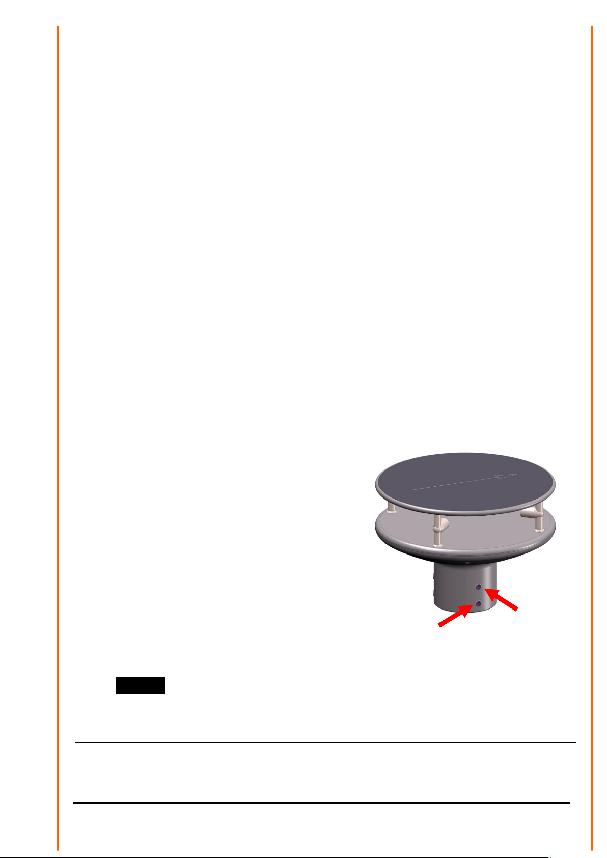
4 Preparation for operation
Attention:
The working position of the anemometer is vertical (North
arrow on the top).
During installation, de-installation, transport or maintenance of
the anemometer it must be ensured that no water gets into the
bottom and connector or cable gland of the anemometer.
When using a lightning rod take care that it be installed in a
angle of 45 ° to a measuring transducer; otherwise there will be
deviations in the measured values.
4.1 Selection of installation site
As described above, the ultrasonic anemometer transmits sound packages required to measure the
propagation speed. If these sound packages meet surfaces that reflect sound well, they are
thrown back as an echo and can may result in incorrect measurements under unfavourable
conditions.
It is therefore advisable to install the ultrasonic anemometer at a minimum distance of 1 metre to
objects in the measuring level.
The choice of the installation location depends on the task position (e.g., data acquisition for
weather services or for control purposes).
11 - 68 021546/12/17
In general, wind meters should register wind conditions over a wide area. To obtain comparable
values when measuring the ground wind, measurement should be performed at a height of 10
metres above even and undisrupted terrain. Undisrupted terrain means that the distance between
the wind transmitter and the obstruction should be at least ten times the height of the obstruction (s.
VDI 3786, sheet 2). If it is not possible to comply with this provision, the wind meter should be
installed at a height at which measured values are influenced by obstructions located in the vicinity
to the least possible extent (approx. 6 … 10 m above the interference level). On flat roofs the
anemometer should be installed in the middle of the roof and not at the edge to thus avoid any
preferential directions.
The ultrasonic-anemometer has an electro-magnetic compatibility, which is far in excess of the
required standard threshold value.
Within the complete frequency range, required by standard, electro-magnetic fields with 20 V/m
(capacity of the test transmitter) could not affect the measuring value acquisition of the instrument.
In case you intend to install the instrument at transmitter masts or other sources of strong electro-
magnetic radiation, where the local field strength is far above the standard threshold value, please
contact the manufacturer.
4.2 Installation of Anemometer
Mechanical installation
Proper installation of the ULTRASONIC ANEMOMETER 2D compact is carried out using a tube
socket R1½" (Ø 48.3 mm) and at least 40 mm in length. The inside diameter of the tube socket
must be at least 25 mm as the electrical connection of the ULTRASONIC is carried out at the
bottom of the device.
Tool:
Hexagon socket wrench Gr.4
Procedure:
1. Conduct and connect the cable/ plug
connection of the ultrasonic anemometer
through the boring of the mast, tube, bracket
etc.
2. Put the ultrasonic anemometer onto the mast,
tube etc.
3. The ultrasonic anemometer "Positioning".
See chapter 4.3
4. Lock the ultrasonic anemometer afterwards at
the mast by the four M8 hexagon socket
screws.
Caution:.
The allen screws must be tightened to
max. 7 Nm
12 - 68 021546/12/17
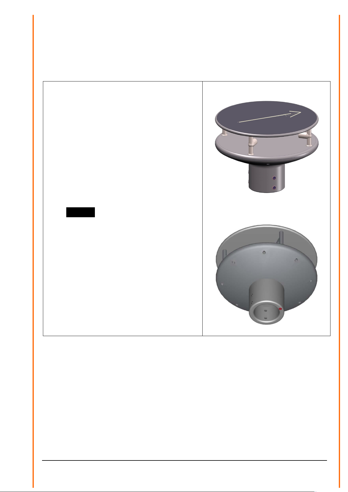
4.3 Alignment to north / Positioning
North Alignment (Positioning) of the Anemometer at a Weather Station
For the accurate determination of the wind direction, the anemometer must be positioned to the
north.
Procedure:
1. „Position“ the ultrasonic anemometer by
rotating on the mast tube until the
Orientation arrow indicates to northern
direction (geographical north).
For this, please choose, in advance, a
prominent point of the land scape in northern
or southern direction by using a compass, und
and rotate the mast or the anemometer until
the Orientation arrow indicates to northern
direction (geographical north).
2. Lock the ultrasonic anemometer afterwards at
the mast by the four M8 hexagon socket
screws.
Caution:.
The allen screws must be tightened to
max. 7 Nm
Note:
When aligning the instrument to north using a
compass, the magnetic variation (= deviation in
direction of compass needle from true north) and local
interfering magnetic fields (e.g. iron parts, electric
cables).
As additional positioning aid, or for a simple change
without re-alignment you may use also the position
drillingin the base. Precondition, however, is a
preparation by user at the mast.

13 - 68 021546/12/17
Positioning of an Anemometer on a Wind Power Plant
For the exact determination of the wind direction the anemometer must be mounted in alignment
with the generator hub.
Procedure (at generator hub north):
1. „Position“ the ultrasonic anemometer by rotating on the mast tube, until the orientation
arrow (in parallel to the generator axis) indicates towards the generator-hub.
2. Lock the ultrasonic anemometer afterwards through the four M6 hexagon socket screw at
the mast.
Caution:.
The allen screws must be tightened to max. 7 Nm
Remark:
In order to avoid the discontinuity of the wind direction at the north leap (360 … 1°) the ultrasonic
anemometer should be aligned oppositely to the generator hub by means of the reference arrow.
Positioning of an Anemometer on a Ship
For the exact determination of the wind direction the anemometer must be mounted in alignment
with the roll-axis, where the bow is related to „0 °“ (north).
Procedure:
1. „Position“ the ultrasonic anemometer by rotating on the mast tube, until the orientation
arrow (in parallel to the generator axis) indicates towards the generator-hub.
Remark:
If the anemometer is far away from the roll-axis (center line bow-rear), a parallel line (bow-
rear) should be assumed.
2. Lock the ultrasonic anemometer afterwards through the four M6 hexagon socket screw at
the mast.
Caution:.
The allen screws must be tightened to max.7 Nm
4.4 Electrical Installation for Ultrasonic Anemometer
The ultrasonic anemometer is equipped with a plug for electrical connection. A coupling socket
(mating) is included in delivery. It is located in the lower part of the transport packing.
14 - 68 021546/12/17
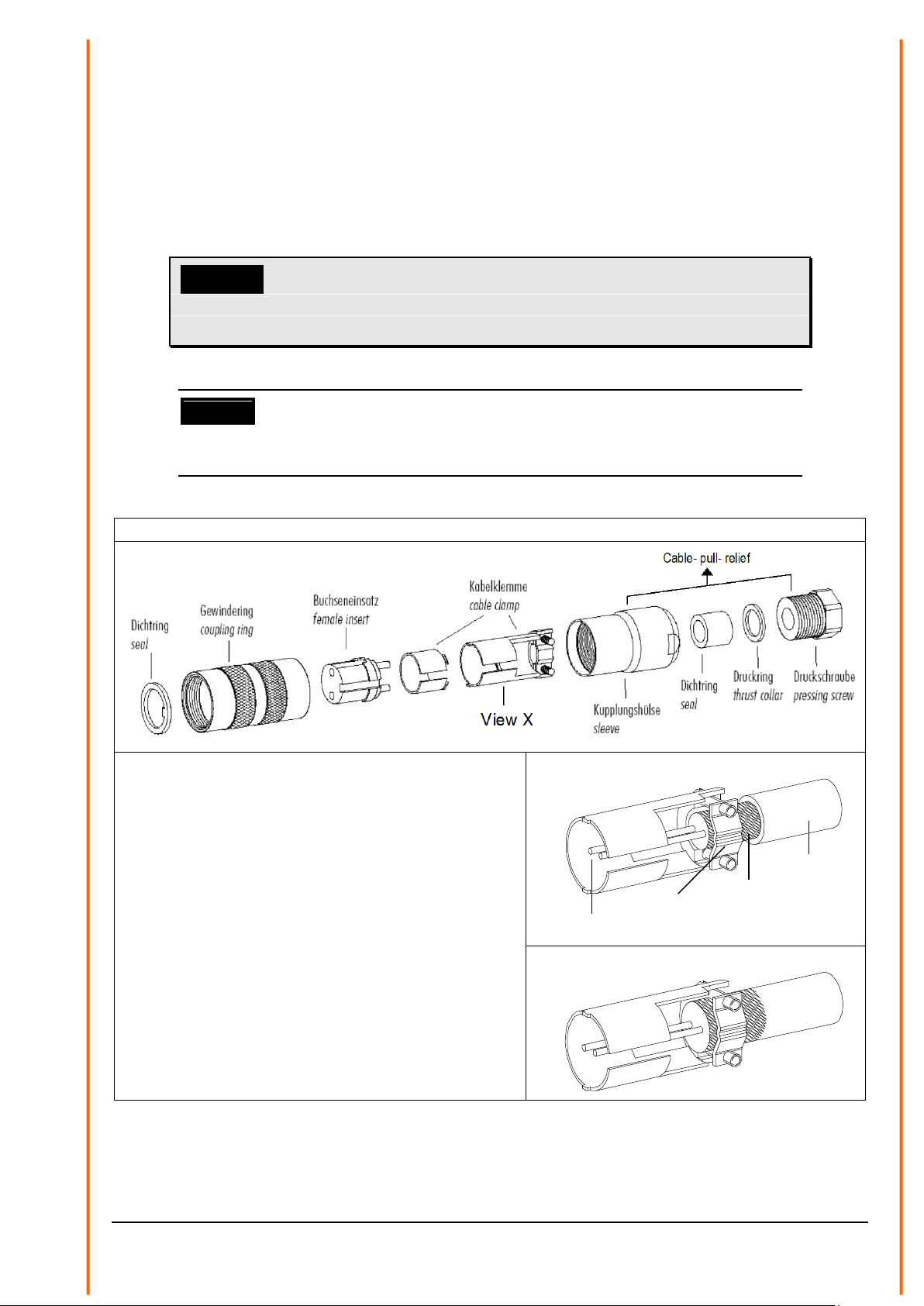
4.4.1 Cables, Cable preparation, Connector Installation
For pin assignment please refer to supplement „factory settings“. Examples see
chapter 3.4.2.
The cable must have the following properties:
8 cores; 0.5 … 0.75 mm² core cross-section for supply ; min. 0.14 mm² core cross-section for data
communications ; 7 … 8 mm cable diameter, resistant to ultraviolet rays, overall shielding.
Coution:
The cable to be connected must be at least the operating
voltage class 01 correspond HAR (100 V).
Remark:
Optionally, a completely converted connecting cable can be included in delivery
for the ultrasonic-anemometer (see accessories).
Coupling socket 507550, 8-pol., (Binder, Serial 423), EMC with cable clamp
1. Stringing parts on cable acc. to plan given above.
2. Stripping cable sheath 20 mm
Cutting uncovered shield 15 mm
Stripping wire 5 mm.
Cable mounting 1
Putting shrink hose or insolating tape between
wire and shield.
Cable mounting 2
If cable diameter permits, put the shield backward
on the cable sheath.
3. Soldering wire to the insert, positioning shield in
cable clamp.
4. Screwing-on cable clamp.
5. Assembling remaining parts acc. to upper plan.
6. Tightening pull-relief of cable by screw-wrench
(SW16 und 17).
Cable mounting 1
Viev X
wire
Cable clamp
shield
Cable shield
Cable mounting 2
Viev X
Figure 1: Connector installation
15 - 68 021546/12/17
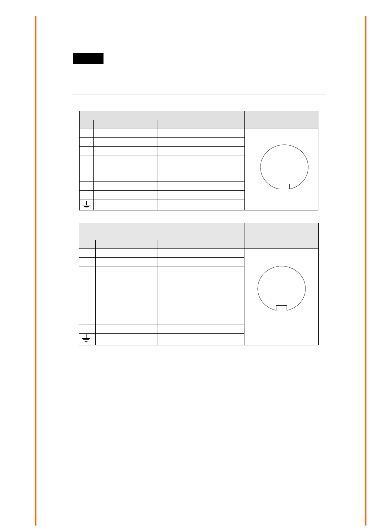
4.4.2 Connector Pin Assignment (Examples of Function)
Remark:
- For exact allocation of function please refer to supplement “Factory Settings”
- The pins 1 – 6 (incl.) are galvanically isolated from the supply voltage and from
housing.
•
Serial Interface, Full-duplex
View of solder terminal
of coupling socket
Pin
Allocation
Function
1
RXD-
Serial interface
2
TXD-
Serial interface
3
CONTROL
Function programmable
4
RXD+
Serial interface
5
TXD+
Serial interface
6
AGND
Ground for serial interface
7
24 V AC/DC nominal
(-) Voltage supply
8
24 V AC/DC nominal
(+) Voltage supply
Shield
•
Serial Interface, Half-duplex and
analogue outputs
View of solder terminal
of coupling socket
Pin
allocation
Function
1
WG
Analogue output wind speed
1
2
3
4
5
6
7
8
2
TXD- / RXD-
Serial interface
3
CONTROL
Function programmable
4
WR
Analogue output wind
direction
5
TXD+ / RXD+
Serial interface
6
AGND
Ground for analogue output
and serial interface
7
24 V AC/DC nominally
(-) Voltage supply
8
24 V AC/DC nominally
(+) Voltage supply
Shield
* reverse-polarity protected
1
2
3
4
5
6
7
8

16 - 68 021546/12/17
5 Maintenance
As the instrument does not have moving parts, i.e. is not subject to wear during operation, only
minimal servicing is required. The instrument is subject to natural pollution, the level of pollution
depends on the location. If necessary the instrument and the sensor surfaces can be cleaned from
soil Cleaning can be carried out as required using non-aggressive cleaning agents in water and a
soft cloth during routine checks.
Attention:
During storage, installation, de-installation, transport or
maintenance of the anemometer it must be ensured that no
water gets into the instrument stand and plug of the
anemometer.
6 Calibration
The ultrasonic anemometer does not contain any adjustable components such as electrical or
mechanical trimming elements. All components and materials used show invariant behaviour in
terms of time. This means that no regular calibration is required due to ageing. Errors in measured
values can only be caused by coarse mechanical deformation of the instrument and associated
changes in measurement path lengths.
The acoustic-virtual temperature can be used to check the effective-acoustic measurement path
length. A change of approx. 0.3 % in the measurement path length and thus a measuring error of
approx. 0.3 % for the wind velocity corresponds to a deviation in the virtual temperature of 1 K at 20
°C; there is a measuring error of approx. 1% for the wind velocity with a deviation of acoustic-virtual
temperature of approx. 3.4 K.
In the event of any change in the measurement paths of the anemometer the manufacturer should
be consulted regarding recalibration.
Important:
Mechanical damages with deformation of the instrument might
lead to measuring value errors.
7 Warranty
Damage caused by improper handling or external influences, e.g. lightning, do not fall under the
warranty provisions. The warranty entitlement expires if the instrument is opened.
Important:
The ultrasonic anemometer must be returned in the original
packaging as the warranty entitlement otherwise expires with
mechanical damage, e.g. deformation of measuring arms.

17 - 68 021546/12/17
8 Functional description
The functioning of the ULTRASONIC instrument is described below. Due to the limited number of
plug connections some functions exclude the simultaneous operation with other functions. Such
dependency is described in each case. There are also restrictions regarding the functional
definition of the cable connector. This is due to the double assignment of individual PINs.
8.1 Serial communication
The ULTRASONIC provides an RS485 / RS422 interface for serial communication. It can be
operated either in full or half duplex mode and at different baud rates.
The communication with the ULTRASONIC can be carried out, for example, by means of a
standard terminal program, in example, you can use the terminal software Tera Term.
On starting the ULTRASONIC the following parameters are output: firmware version, creation date
of firmware, serial number of instrument, system time, instrument ID as well as the duplex-mode of
the serial interface and the used command interpreter. The output is carried out with the last set
and stored baud rate.
Example:
------------------------
THIES-ULTRASONIC-COMPACT
Bootloader: V1.1
Version: 3.00 / RV0000
Feb 2 2016 / 07:40:35
Serial-No.: 000000000
System-Time: 8:57:58
System-ID.: 00
Serial-COM: 4-wire RS422
Interpreter: Thies
------------------------
Help: 00??<CR>
------------------------
The example shows that the ULTRASONIC with the instrument ID 00 is operating in full duplex
mode, and that the Thies interpreter is used, see command CI.
8.1.1 Duplex mode
Duplex mode decides the type of physical connection of the serial interface. In full duplex mode the
send and receive signals are each transmitted via separate pairs of cables. This means it is
possible to send and receive signals at the same time.
In half duplex mode transmission of the send and receive signals is via the same pair of cables in
the time division (successively) (: see Command DM.
For a bus operation in the half-duplex-mode (RS485), where the ULTRASONIC, in general, is
operated as “slave”, it is necessary to switch the line-transmitter into the “high–impedance-state”
during the intermission, so that the replies of the other bus parties are not suppressed.
It might be important with point-to-point-connections in the full-duplex-mode (RS422), depending on
the disturb-ratio on the communication lines, that the line-transmitter remains active during the
intermissions. So, a maximum differential input level leads to a maximum signal/noise ratio.

18 - 68 021546/12/17
A half-duplex-mode can be selected via the Command DM (duplex mode). With this mode, on
principle, the line-transmitter is switched on only when sending. For the full-duplex-operation there
are two modes: one for bus operation (RS485), where the line-transmitter is controlled as in half-
duplex mode, and another one (RS422), where the line-transmitter remains active even in case of
reception. See Command DM.
For the ULTRASONIC there are restrictions on the parameter combination or function of the
terminals depending on the transmission type selected. Due to the limited number of plug
connector contacts multiple assignment of the connections are necessary. The following table
shows the functional options for the modes full and half duplex.
Full duplex mode
Half duplex mode
Bus mode possible (RS 485, DM=1)
Bus mode not possible (RS 422, DM=2)
Bus mode possible (RS 485, DM=0)
No output of analogue values to PIN RXD- and
RXD+
Output of analogue values possible at PIN RXD-
and RXD+
Heating control via PIN CONTROL possible
Heating control via PIN CONTROL possible
Table 1: Restrictions in full and half duplex mode
8.1.2 Response Delay
With the serial communication please take into consideration that the ULTRASONIC responds
immediately to arriving telegrams. The response time of the instrument is in the lower range of
milliseconds. Possibly, the delay between receiving signal and sending signal might be too short for
some interface converters. It is possible that, within this time period, the interface converter has not
yet switched over from the mode ‘sending’ to the mode ‘receiving’. This might lead to absurd
telegrams.
In order to avoid this effect, the ULTRASONIC has the parameter RD (response delay). With this
parameter the response is additionally delayed, on receipt, by the selected value in milliseconds.
The setting of the parameter on state of delivery depends on the instrument number.
8.1.3 General telegram structure for the Thies Interpreter.
For serial communication the ULTRASONIC has a fixed telegram format, which also permits
communication in bus mode. It has the following form:
NNBB<cr> <cr> stands for Carriage return (Enter key)
for a data enquiry or
NNBBPPPPP<cr> <cr> stands for Carriage return (Enter key)
for a parameter change.
The individual letters have the following meaning:
NN: Two-digit ID of the ULTRASONIC. It can be selected in the range from 00 to 99. The
presetting is the ID '00': see also Command ID.
BB: Two-position command. A complete list can be found in section Command list.
PPPPP: The parameter input is always left-justified and can range from 0 to 5-digit
value.

19 - 68 021546/12/17
Examples:
1. Telegram number 2 shall be queried. The respective command is:
00TR2<cr> <cr> stands for Carriage Return (enter button)
alternatively also:
00TR00002<cr> can be entered.
2. Query of baud rate with the command:
00BR<cr> <cr> stands for Carriage Return (enter button)
the selected data record for the baud rate is returned.
!00BR01152 stands for 115200 baud
Requirement in these examples is, that the ULTRASONIC ID has the value ‚00’.
Remark:
The receiving buffer of the ULTRASONIC can be cleared by sending a carriage
return <CR>. If the ULTRASONIC possibly has invalid characters in the receiving
buffer, this buffer can be processed by sending a carriage return. In this case, it is
advisable to send a carriage return at the beginning of the telegram, for example:
<CR>00TR2<CR>
8.1.4 Saving of the ULTRASONIC Parameters
After a change in parameter by the user- or administrator-key, the ULTRASONIC must be reset into
the locked status by the command „00KY0“ (Key „00000“). (In this case the ULTRASONIC ID has
the value „00“).
Only by resetting the key or by storing command (00CS1) the parameters are saved
permanently also beyond a restart.
When restarting the ULTRASONIC without prior saving all changed parameters get lost; therefore,
it is recommendable to save all important parameters after termination of entry by resetting the key
(00KY0), or the by storing command (00CS1).
8.1.5 Return values of ULTRASONIC
After a valid command has been input, the ULTRASONIC sends acknowledgement, e.g.
acceptance of the parameter or output of a data telegram.
For a standard command the response starts with a '!', followed by the ID and the parameter value.
If the input command is TR or TT, the ULTRASONIC transmits a data telegram as the response.

20 - 68 021546/12/17
8.1.6 Access Mode
For configuration the ULTRASONIC has a set of commands, which determine behaviour in terms of
the propagation time. The commands are broken down into three levels:
•Query Mode
•User mode
•Configuration mode
Enquiry mode (“READ ONLY“):
This mode comprises commands, which do not influence the parameters of the ULTRASONIC.
They include for example, output of the system status and interrogation of the data telegram with
TR.
User mode (“USER“):
This mode comprises commands, which affect the behaviour of the ULTRASONIC. These
parameters can be changed by the user. The system behaviour of the instrument is changed with
these commands. This group of commands includes e.g. settings for output scaling and averaging
Configuration mode(“ADMIN“):
This mode comprises commands, which are factory-set for the delivery status.
To distinguish between commands of the three groups when parameterising the ULTRASONIC the
instrument is equipped with an access key KY. Inputting of the key accesses the individual levels.
Access to commands at a higher level includes access to commands at a lower level.
Access key Response from
ULTRASONIC
Command level
00KY00000 READ ONLY
!00KY00000 Query mode (preset)
00KY00001 USER ACCESS
!00KY00001 User mode
00KY04711 ADMIN ACCESS
!00KY04711 Configuration mode
Table 2: Access key for different command levels
After the access key has been changed, the ULTRASONIC transmits a response, which contains
not only the parameter input but also the access mode.
After parameters have been changed with the key '00001' or '04711', the ULTRASONIC must be
reset to the initial position with the command 00KY0, so that the parameter are saved. (see also
chapter 8.1.4).
In case of power supply interruption the instrument is reset automatically to the query mode.
This manual suits for next models
44
Table of contents
Other Thies CLIMA Measuring Instrument manuals

Thies CLIMA
Thies CLIMA First Class Advanced X User manual

Thies CLIMA
Thies CLIMA 4.3223.50 Series User manual

Thies CLIMA
Thies CLIMA Hygro-Thermo Transmitter-compact User manual

Thies CLIMA
Thies CLIMA Ultrasonic Anemometer 2D User manual

Thies CLIMA
Thies CLIMA 5.4110 00 Series User manual

Thies CLIMA
Thies CLIMA 9.2750.xx.90 Series User manual


