Think Simple Vitrum On-Off Classic Owner's manual

HOME CONTROL
THINK SIMPLE
EN
INSTALLATION AND OPERATION
Vitrum On-Off Classic

INDEX
0. Before starting ................ 3
1. Electrical connections ........... 4
2. Positioning the glass decor panel .. 8
3.
Configuration of the type of switch
10
4. Factory reset................. 13
5. Compliance with ec directives ... 15
MAIN TECHNICAL SPECIFICATIONS
.. 14

3
0. BEFORE STARTING
The Vitrum system that you have purchased is designed for connection to your
existing 240V power supply circuit. Before commencing installation, ensure that the
mains power supply had been disconnected by setting the main switch on your
electricity meter to
OFF
.
Do not re-connect the power supply and start using Vitrum
until all connections have been correctly completed and the Vitrum unit has been
inserted into the wall-mounting box.
Vitrum must be installed by a professional electrician who is
qualified to operate on electrical power circuits in full compliance
with all current safety legislation.
For each device, connect the power supply and the return wire from the actuators
as shown in the circuit diagrams printed on the rear of the boxes in the vicinity of
the terminal block. Refer exclusively to the circuit diagrams contained in this manual,
especially if connecting the system without an earth wire.
Carefully check that the wires and connectors are securely fastened. After
securing the unit to the wall-mounting box, temporarily use the plastic cover
for protection until the glass décor plate is fitted.
Do not install Vitrum in the vicinity of sources of heat or in conditions of high humidity.
IMPORTANT: Fit a rapid-acting fuse with a high switching capacity that is
suitable for the load applied to the device.

4
On-off Classic
1 channel EU
On-off Classic
2 channels EU
1. ELECTRICAL CONNECTIONS
Simply connect the Live wire to the terminals marked “L”,”C1...C3”and the
Neutral wire to the terminal marked “N” and the light(s) to the terminal(s) marked
“NO 1...NO 3”.
All the relays function as switches, and the contacts are normally open. The device
may be set to operate as a “Button” as well as a “Switch”.

5
On-off Classic
3 channels EU
On-off Classic
1 channel BS
On-off Classic
2 channels BS
On-off Classic
4 channels BS
6
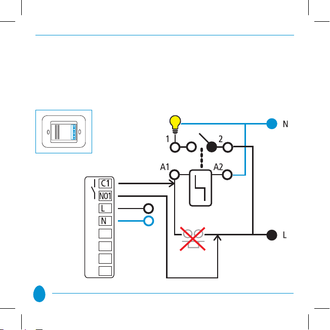
The circuit diagram below shows how to connect without the use of the jumper in
order to replace a button which controls a step relay for control of an existing lighting
system:
Step Relay
Button
to replace

7
IMPORTANT
Fit a rapid-acting fuse with a high switching capacity that is suitable for the load
applied to the device. Recommended fuse to put in series for each channel is: fast-
acting ceramic body cartridge fuse mod. F4AH250V (800W); F6,3AH250V (1500W);
F12,5AH250V (2400W); F16AH250V (4x800W). Devices are built to fit italian “503”
boxes, 3 modules, comply with the standard IEC/EN 60670-1 and dimensional tab
A8 of standard CEI 23-74:2002; 1-gang British Standad boxes, 2 modules, comply
with the standard 4662:2006.
After connecting, check that the wires are correctly positioned inside the wall-
mounting box. When securing Vitrum to the wall-mounting box, use the screws
supplied and note that the maximum torque to be used when tightening the
screws in the embedding box is 0.8 Nm. In addition, the surface of the wall for at
least 2 cm surrounding the embedding box must be as flat and smooth as possible,
and must not have any rough patches and/or bumps that protrude more than 1 mm.
If the screws are not tightened with the torque specified, or if the embedding
box is installed on unsuitable surfaces, the correct operation of the device
cannot be guaranteed.
Think Simple Spa accepts no liability if the device is not correctly installed as described
above.
8
2. POSITIONING THE GLASS DECOR PANEL
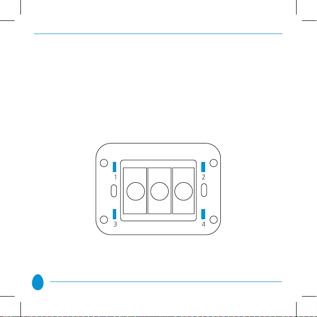
In order to refit the glass panel correctly, ensure that the four plastic tabs on the
panel are in perfect alignment with the anchor holes. When the glass panel tabs
are aligned with the holes, press the four corners of the glass panel evenly until it
is fully inserted into the wall-mounting box.
Anchor holes on electronic section
9
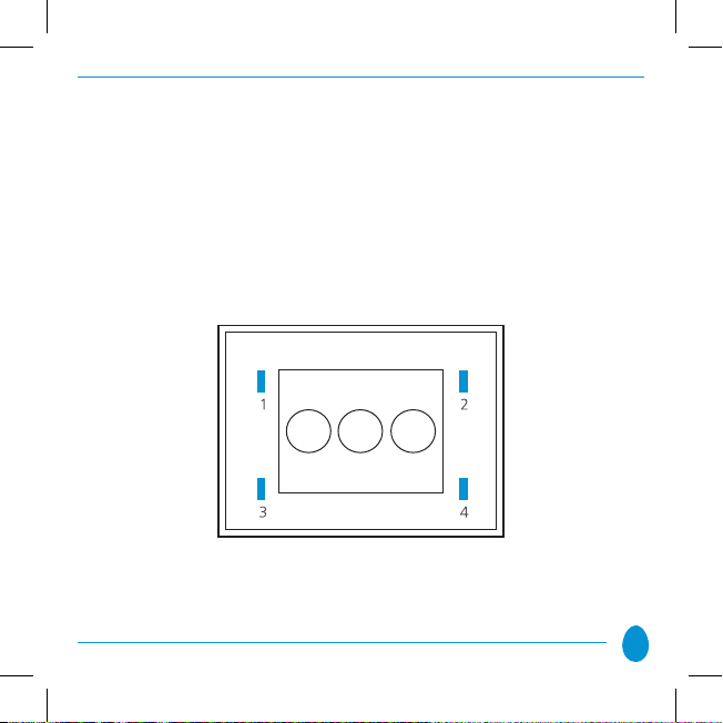
Anchor tabs on décor panel
After fitting the glass panel, the buttons remain inoperative for about 10 seconds.
An acoustic signal sounds three times to indicate that the sensors have been re-
calibrated, after which they resume normal operation. To remove the glass panel
from the wall-mounting box, gently lever the upper or lower edge away.
10
3. CONFIGURATION OF THE TYPE OF SWITCH
Vitrum is configured to operate as a normal ON/OFF switch (i.e. to ‘toggle’ the
ON and OFF status with each touch). The individual channels can be configured
as simple buttons. To do so, proceed as follows:
• Remove the glass décor panel.
• Press and hold down the two service touch keys for at least 8 seconds and
wait until the BEEP sounds twice to indicate that the system has entered the
configuration MENU. The LEDs in the touch keys will begin to flash either
blue or red, depending on the setting entered. The default setting for the
flashing light is blue since the factory setting is Switch.

11
• Press each of the Vitrum touch keys briefly to select the
desired operating mode.
FLASHING BLUE
Switch
Each time the touch key is pressed, the cyclic status is ‘toggled’:
Switch -> Button -> Switch …
FLASHING RED
Button

12
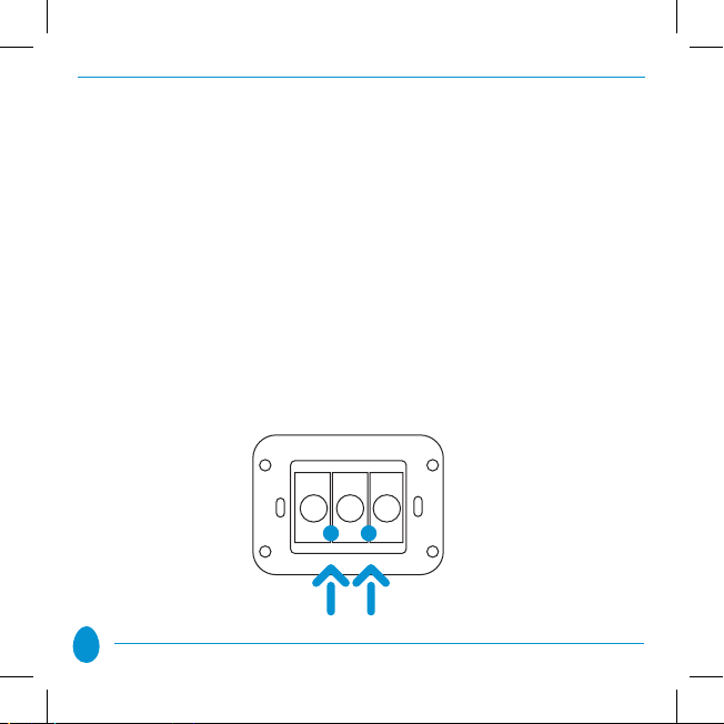
Vitrum returns to normal operation after 12 seconds of inactivity or if the two service
touch keys indicated by the yellow arrows in the figure below are pressed briefly
(0.5 seconds).
IMPORTANT
The default operating mode is “Switch”.

13
4. FACTORY RESET
Proceed as follows to reset the Vitrum unit to the original factory settings:
• Remove the Vitrum unit from the wall-mounting box.
• Press the hidden Factory Reset button and hold down for at least 3 seconds.
Vitrum will flash red three times and sound an acoustic signal to indicate that the
original factory setting has been restored.
14
MAIN TECHNICAL SPECIFICATIONS
Vitrum On-off Classic
Power supply
Energy consumption
Operating temperature
Relay
Load capacity for each
output (see data sheet)
Configurable
operating mode: switch
or hold-down button
Protection Rating
Vitrum Vitrum Vitrum Vitrum
1 channel 2 channels 3 channels 4 channels
240V/50hz 240V/50hz 240V/50hz 240V/50hz
<1 w <1 w <1 w <1 w
0-40° C 0-40° C 0-40° C 0-40° C
16 A 16 A 16 A 5 A
Up to Up to Up to Up to
2400w 2400w 2400w
800w/800VA
YES YES YES YES
IP 40 IP 40 IP 40 IP 40

15
5. CONFORMITà ALLE DIRETTIVE
All Vitrum Classic units are built in compliance with the following European directives:
B.T.2006/95/CE, E.M.C.:2004/108/CE,
The manufacturer assumes no responsibility for any use not indicated in this
manual.
Think Simple reserves the right to modify its products at any time and without notice
in order to better their quality and functionality.
Therefore, all the information given in this datasheet is to be considered subject to
possible modifications. For this reason we invite you to check for update of Vitrum
users guide at www.vitrum.com/eng/content/download
To discover further functions and products by
VITRUM please visit our site:
www.vitrum.com

HOME CONTROL
THINK SIMPLE
by
Think Simple SpA
Head Office
viale Lino Zanussi, 3 Tel +39 0434 516 216
33170 Pordenone Fax +39 0434 516 230
Sales Office
corso Garibaldi, 86 Tel +39 02 655 600 29
20121 Milano Fax +39 02 454 982 95
www.thinksimple.it [email protected]
I000109 - 07/2011
Table of contents


