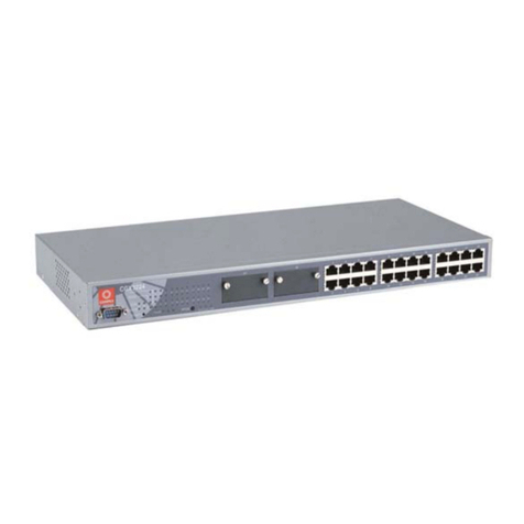
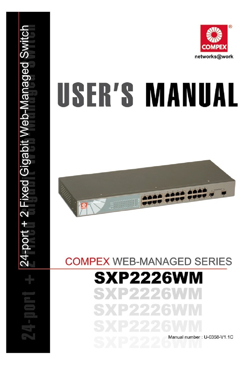
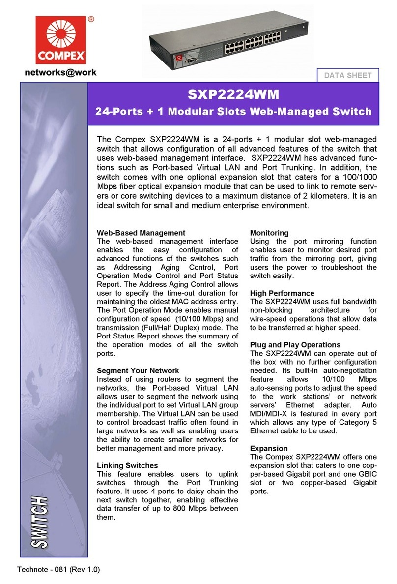
Compex SXP2224WM User manual


i
© Copyright 2005 Compex Systems Pte Ltd
All Rights Reserved
This document contains information, which is protected by copyright. Reproduction, adaptation
or translation without prior permission is prohibited, except as allowed under the copyright
laws.
Trademark Information
Compex®, ReadyLINK®and MicroHub®are registered trademarks of Compex, Inc. Microsoft
Windows and the Windows logo are the trademarks of Microsoft Corp. NetWare is the
registered trademark of Novell Inc. All other brand and product names are trademarks or
registered trademarks of their respective owners.
Notice: Copyrights © 2005 by Compex, Inc. All rights reserved. Reproduction, adaptation, or
translation without prior permission of Compex, Inc. is prohibited, except as allowed under the
copyright laws.
Manual Revision by Ong
Manual Number: U-0374-V1.2C Version 1.2, February 2005
Disclaimer
Compex, Inc. provides this manual without warranty of any kind, either expressed or implied,
including but not limited to the implied warranties of merchantability and fitness for a particular
purpose. Compex, Inc. may make improvements and/or changes to the product and/or
specifications of the product described in this manual, without prior notice. Compex, Inc will
not be liable for any technical inaccuracies or typographical errors found in this guide. Changes
are periodically made to the information contained herein and will be incorporated into later
versions of the manual. The information contained is subject to change without prior notice.
Your Feedback
We value your feedback. If you find any errors in this user’s manual, or if you have suggestions
on improving, we would like to hear from you. Please contact us at:
Fax: (65) 62809947
Email: [email protected]

ii
FCC NOTICE
This device has been tested and found to comply with the limits for a Class A digital device,
pursuant to Part 15 of the FCC Rules. These limits are designed to provide reasonable
protection against harmful interference in a residential installation. This device generates, uses
and can radiate radio frequency energy and, if not installed and used in accordance with the
instructions, may cause harmful interference to radio communications. However, there is no
guarantee that interference will not occur in a particular installation. If this device does cause
harmful interference to radio or television reception, the user is encouraged to try to correct the
interference by one or more of the following measures:
• Reorient or relocate the receiving antenna.
• Connect the computer into an outlet on a circuit different from that to which the receiver is
connected.
• Increase the separation between the computer and receiver.
• Consult the dealer or an experienced radio/TV technician for help.
Caution: Any changes or modifications not expressly approved by the grantee of this device
could void the user's authority to operate the equipment.
FCC Compliance Statement: This device complies with Part 15 of the FCC Rules. Operation
is subject to the following two conditions:
1. This device may not cause harmful interference, and
2. This device must accept any interference received, including interference that may cause
undesired operation.
Declaration of Conformity
Compex, Inc. declares the following:
Product Name: Compex 24-Port 10/100 + 1 Modular Exp. Slot Web-managed Switch
Model No: SXP2224WM conforms to the following Product Standards:
This device complies with the Electromagnetic Compatibility Directive (89/336/EEC) issued by
the Commission of the European Community.
Electromagnetic Interference (Conduction and Radiation): EN 55022 (CISPR 22)
Electromagnetic Immunity: EN 55024 (IEC61000-4-2,3,4,5,6,8,11)
Power Line Harmonics: EN 61000-3-2 (IEC610000-3-2)
Power Line Flicker: EN 61000-3-3 (IEC610000-3-3)
Product Safety: EN 60950 (IEC60950)
Therefore, this product is in conformity with the following regional standards: FCC Class A ⎯
following the provisions of FCC Part 15 directive; CE Mark ⎯following the provisions of the
EC directive.
This Class A digital apparatus complies with Canadian ICES-003.

iii
Technical Support Information
The warranty information and registration form are found in the Quick Install Guide.
For technical support, you may contact Compex or its subsidiaries. For your convenience, you
may also seek technical assistance from the local distributor, or from the authorized
dealer/reseller that you have purchased this product from. For technical support by email, write
Refer to the table below for the nearest Technical Support Centers:
Technical Support Centers
Contact the technical support center that services your location.
U.S.A., Canada, Latin America and South America
Write
Compex, Inc.
840 Columbia Street, Suite B,
Brea, CA92821, USA
Call
Fax
Tel:
Tel:
Fax:
+1 (714) 482-0333 (8 a.m.-5 p.m. Pacific time)
+1 (800) 279-8891 (Ext.122 Technical Support)
+1 (714) 482-0332 Europe
Write
ReadyLINK Networktechnology GmbH
Albert Einstein Straβe 34/M21
63322 Rödermark, Germany
Call
Fax
Tel:
Fax:
+49 (0) 6074 - 98017 (8 a.m.-5 p.m. local time)
+49 (0) 6074 - 90668
Asia, Australia, New Zealand, Middle East
and the rest of the World
Write
Compex Systems Pte Ltd
135, Joo Seng Road #08-01, PM Industrial Building
Singapore 368363
Call
Fax
Tel:
Tel:
Fax:
(65) 6286-1805 (8 a.m.-5 p.m. local time)
(65) 6286-2086 (Ext.199 Technical Support)
(65) 6283-8337
Internet
access/ E-mail:
FTPsite: support@compex.com.sg
ftp.compex.com.sg
Website: http://www.cpx.com or http://www.compex.com.sg

i
About This Document
The product described in this document, Compex Web Management Switch Series, Compex
SXP2224WM is a licensed product of Compex Systems Pte Ltd. This document contains
instructions for installing, configuring and using Compex SXP2224WM. It also gives an
overview of the key applications and the networking concepts with respect to the product.
This documentation is for both Network Administrators and the end user who possesses some
basic knowledge in the networking structure and protocols.
It makes a few assumptions that the host computer has already been installed with TCP/IP and
already up & running and accessing the Internet. Procedures for Windows
95/98/2000/XP/ME/NT operating systems are included in this document. However, for other
operating system, you may need to refer to your operating system’s documentation for
networking.
How to Use this Document
The document is written in such a way that you as a user will find it convenient to find specific
information pertaining to the product. It comprises of chapters that explain in details on the
installation and configuration of Compex SXP2224WM.
Firmware
This manual is written based on Firmware version 4.23.
Conventions
In this document, special conventions are used to help and present the information clearly. The
Compex 24-Port 10/100 + 1 Modular Exp. Slot Web-managed Switch is often referred to as
Compex SXP2224WM in this document. Below is a list of conventions used throughout.
NOTE
This section will consist of important features or instructions
CAUTION
This section concerns risk of injury, system damage or loss of data
WARNING
This section concerns risk of severe injury
References on Menu Command, Push Button, Radio Button, LED and Label appear in Bold.
For example, “Click on the “Ok” button”

Table of Contents
ii
Copyrights © 2005 Compex Systems Pte Ltd..................................................................................i
Trademark Information.....................................................................................................................i
Disclaimer ........................................................................................................................................i
Your Feedback..................................................................................................................................i
FCC NOTICE..................................................................................................................................ii
Declaration of Conformity...............................................................................................................ii
Technical Support Information.......................................................................................................iv
About This Document .....................................................................................................................v
How to Use this Document..............................................................................................................v
Firmware .........................................................................................................................................v
Conventions.....................................................................................................................................v
Chapter 1 Product Overview.................................................................................... 1
1.1 Introduction............................................................................................................................1
1.2 Features and Benefits.............................................................................................................1
1.3 Panel Views............................................................................................................................3
1.4 Panel Features........................................................................................................................4
1.5 Specifications.........................................................................................................................5
Chapter 2 Getting Started ........................................................................................ 7
2.1 Packaging Content .................................................................................................................7
2.2 Setup Considerations..............................................................................................................7
2.2.1 Software Requirements..............................................................................................7
2.2.2 Hardware Requirements ............................................................................................7
Chapter 3 Network Applications.............................................................................. 8
3.1 Small workgroup....................................................................................................................8
3.2 Segment Bridge......................................................................................................................9
Chapter 4 Hardware Installation........................................................................... 10
4.1 Desktop installation..............................................................................................................10
4.2 Rack installation...................................................................................................................11
4.3 Installation of Expansion Module ........................................................................................12
4.3.1 Removal of Expansion Module................................................................................13
4.4 Connecting Console cable to Compex SXP2224WM ..........................................................13
4.4.1 Configure Hyper Terminal Program........................................................................13
Table of Contents
iii
Chapter 5 Access to Web Interface........................................................................ 14
5.1 Configuration on PC settings ...............................................................................................14
5.2 Configuration of Compex SXP2224WM using Web-based Interface..................................15
5.2.1 Login to Web Browser Interface..............................................................................15
Chapter 6 Configure Compex SXP2224WM using Web Interface..................... 18
6.1 Port Status............................................................................................................................18
6.2 Port Configuration................................................................................................................19
6.3 Trunk Configuration.............................................................................................................20
6.3.1 Examples on Port Trunking.....................................................................................21
6.4 Virtual LAN Configuration..................................................................................................23
6.4.1 Example on PortBased VLAN.................................................................................23
6.5 Port Monitoring Configuration.............................................................................................28
6.5.1 Examples on Port Monitoring..................................................................................28
6.6 QoS Configuration ...............................................................................................................30
6.7 Bandwidth Control...............................................................................................................32
Chapter 7 Miscellaneous Operation....................................................................... 33
7.1 Advanced Switch Configuration ..........................................................................................33
7.2 Password Setting..................................................................................................................34
7.2.1 Retrieval of password ..............................................................................................34
7.3 Backup & Restore Settings...................................................................................................35
7.4 Restore System Default Setting............................................................................................35
7.5 Reboot System .....................................................................................................................36
7.6 System Information..............................................................................................................36
7.7 IP Configuration...................................................................................................................37
7.8 Technical Support ................................................................................................................37
7.9 Logout..................................................................................................................................37

Chapter 1 Product Overview
1
Chapter 1 Product Overview
1.1 Introduction
The Compex SXP2224WM is a 24-ports 10/100 Mbps + 1 modular slot web-managed
switch that offers fiber or copper-based gigabit connectivity through its expansion
modules. The SXP222WM comes with enhanced features that can be catered for
today’s most demanding Ethernet-based switching applications. It is the most ideal
workgroup switch for any small and medium enterprises.
1.2 Features and Benefits
Compex SXP2224WM is designed with the following features:
• 1 modular port for 1000Base-T or 1000Base-FX
Compex SXP2224WM is designed with an expansion slot which supports 2
types of optional modules: 2 Gigabit Copper Module and 1000T Gigabit Copper
+ 1 GBIC slot.
• Web-based Management Interface
Compex SXP2224WM is embedded with a HTTP server, facilitating a simple
configuration process with a user-friendly web-based interface. Simply connect
Compex SXP2224WM to a workstation and configure the switch for your
network via a Java-enabled web browser.
Through the management interface, you can also change the transmission mode
of all ports on Compex SXP2224WM switch. This means that you can change
the operating mode of any port to 10 Base-T half duplex, 10 Base-T full duplex,
100 Base-TX half duplex, 100 Base-TX full duplex or N-way Auto-negotiation
at any time.
• Port Trunking increases cascading bandwidth
Up to 7 groups may be defined for Port Trunking, delivering up to 800Mbps
cascading bandwidth between two switches.

Chapter 1 Product Overview
2
• Port Mirroring for monitoring purposes
This function allows you to set up a ‘mirror’ port on any specified port/s, such
that you can monitor the traffics of the monitored port/s without intervening
them. In effect, the traffics on the monitored port/s are replicated on the mirror
port, such that you can use a protocol analyzer to analyze the traffic for specific
problem.
• Port Priority for traffic prioritization (QoS)
Compex SXP224WM supports first come first serve basis. You can set the port
priority according to the types of operations you are working in.
• Bandwidth Control for limiting network bandwidth
Bandwidth control allows you to specify the maximum line bandwidth that a
particular transfer operation can use, so that it can be carried out at low priority
in the background without interfering any users or network applications. It is
ideally suitable for interactive network users.
• Virtual LAN (VLAN)
Compex SXP2224WM can support both port-based and 802.1Q VLANs. It
allows network administrator to separate the network into a few segments by
defining which port belong to which VLAN segment. This can effectively
control broadcast and multi-cast packet flooding the network. This not only
improves the network performance, but also provides security between
workgroups.

Chapter 1 Product Overview
3
4 3
5 6
1.3 Panel Views
Figure 1.3a Front Panel View of Compex SXP2224WM
Figure 1.3b Front Panel View of Compex SXP2224WM (Section #1)
Figure 1.3c Front Panel View of Compex SXP2224WM (Section #2)
Figure 1.3d Back Panel View of Compex SXP2224WM
7
1 2

Chapter 1 Product Overview
4
1.4 Panel Features
Features Status and Indication
Steady Green The port is connected to the switch.
Blinking Green The port is transmitting or receiving data.
1 LNK/ACT LEDs
Off There is no connection established in the
network.
Steady Amber The port is operating in Full Duplex mode.
Off The port is operating in Half Duplex mode.
2 FDX/COL LEDs
Blinking Amber Collision occurs in the network segment of
the respective port.
Steady Green Power is supplied to the switch.
3 Power LED
Off No power is supplied to the switch.
4 Console Port A serial 9 Pin (DB9) RS232 straight socket is connected to PC
COM Port for monitoring the switch.
5 24 RJ45
Management Ports Connect to web-browser via RJ45 UTP/STP network cable
• 10Base-T
• 100Base-TX
• Auto-negotiation
6 Open Expansion
Module Slot Types of Optional Module used:
• SXM1000T/2: 2 Gigabit Copper Module
• SXM1000T/GBIC: 1 Gigabit Copper + 1 GBIC (3.3V) slot
7 Power Socket Flexible power input (range 100VAC ~ 240VAC, 50~60Hz)

Chapter 1 Product Overview
5
1.5 Specifications
• Industry Standards Complies with
• IEEE 802.3 10Base-T
• IEEE 802.3u 100Base-TX
• IEEE 802.3ab 1000Base-T
• IEEE 802.1p Priority Queuing
• IEEE 802.1ad Port Trunk
• Safety Certifications • CE Mark
• FCC Part 15 Class A
• Gost
• C-Tick
• UL
• Interface • 24 RJ45 UTP 10/100 Mbps ports that supports half/full
duplex modes
• 1 expandable slot
• 1 RS232 serial interface
• Protocol CSMA/CD
• Transmission Mode • Full Duplex
• Half Duplex
• LED Indicators • LNK/ACT
• FDX/COL
• Power
• Optional Modules • SXM1000T/2: 2 Gigabit Copper Module
• SXM1000T/GBIC: 1 Gigabit Copper + 1 GBIC (3.3V)
slot
• Switching Method Store and Forward
• Management • Console Interface
• Web-based Management Interface
• MAC Address Table 6K

Chapter 1 Product Overview
6
• Transfer Rate • 14,880pps Ethernet port
• 148,800pps Fast Ethernet port
• 1488,000pps Gigabit port
• Packet Buffer 3Mbits
• Back Plane Capacity 8.8Gbps
• Bandwidth Control Per port support bandwidth control.
• Virtual LAN Port-based VLAN with VLAN ID up to 255
• Port Trunking Provide 7 trunk groups of a maximum of 4 member ports
(minimum 2 member ports) within 24 ports.
• Port Monitoring Global System support 3 mirroring type RX, TX and both
packet. The maximum of mirror entries up to 25.
• Priority Queuing Supports 8 priority levels ID for high/low priority queue.
• Physical Dimension 440mm x 161mm x 44mm (L x B x H)
Operating temperature
Storage temperature
Operating humidity
Storage humidity
: 0ºC to 45ºC
: -20ºC to 70ºC
: 10% to 90% RH
: 5% to 90% RH
• Environmental
Requirements
RH = Relative Humidity

Chapter 2 Getting Started
7
Chapter 2 Getting Started
This chapter outlines the basic requirement for any installation and configuration of Compex
SXP2224WM.
2.1 Packaging Content
Thank you for purchasing the Compex Web Managed Switch SXP2224WM. You will
find the following items in the package:
• 1 x Compex SXP2224WM unit
• 4 x rubber foot
• 1 x Power Cord
• 2 x brackets
• 8 x screws
• 1 x RS232 serial console cable
• 1 x Quick Install Guide with warranty card
• 1 x Product CD (Web browser, Acrobat Reader, User’s Manual)
2.2 Setup Considerations
Prepare checklist before you start:
.
• Check your Local Area Network configurations. Check if the network has Static
IP addressing or dynamic IP assignment.
• Check whether any of the browsers (Netscape Navigator, Netscape
Communicator or Microsoft Internet Explorer) is installed in your PC.
2.2.1 Software Requirements
• Windows 95/98/2000/NT/ME/XP
• Any other TCP/IP-enabled systems like Mac OS and UNIX
• Web Browser, such as Microsoft Internet Explorer (4.0 and above) or
Netscape Navigator (4.0 and above)
2.2.2 Hardware Requirements
• RJ45 Category 3, 4 or 5 MDI or MDXI Ethernet cable and Compex
SXP2224WM unit

Chapter 3 Network Applications
8
Chapter 3 Network Applications
Compex SXP2224WM is ideally suitable for interconnecting networking segments. It is a multi-
port switch that can be used to build high-performance switched workgroup networks. It
supports auto MDIX/MDX which allows you to connect to another Ethernet switch or
workstations without changing straight or cross-over network cable.
3.1 Small workgroup
In the illustration stated below, Compex SXP2224WM can be used as a standalone
switch to which workstations, server, printer server are directly connected to form a
small workgroup.
Figure 3.1a Small workgroup application
PC 1 PC 2 PC 3 Server
Printer
Server
Compex
SXP2224WM

Chapter 3 Network Applications
9
3.2 Segment Bridge
For enterprise company, bulky data broadcasts are constantly processed. Compex
SXP2224WM is ideally suitable for department users to connect to the corporate
backbone.
From the illustration shown below, Compex SXP2224WM is attached to a uplink
backbone. Two Ethernet switches are connected to Compex SXP2224WM. All
devices in the network can communicate with one another through Compex
SXP2224WM. A server is connected to the switch to allow users from accessing the
data on the server.
Figure 3.2a Department Bridge Application
PC 1 PC 2 PC 3
Server
Printer
Server
Compex
SXP2224WM
PC 4 PC 5 PC 6
Backbone Link
Gigabit Port
10/100Mbps
Port
Switch 1 Switch 2

Chapter 4 Hardware Installation
10
Chapter 4 Hardware Installation
Compex SXP2224WM can be installed as a desktop unit or mounted on a 19-inch rack. There
are two types of installation for Compex SXP2224WM, one is to connect your PC directly to
the management port. Alternatively, you can configure by linking the management port to one
of the LAN ports and configure the switch through one of the ports. Detailed installation
process will be listed as shown below.
4.1 Desktop installation
1. Unpack Compex SXP2224WM.
2. Place it near to a power outlet. Ensure that there is sufficient space for heat
ventilation.
3. The surface to place Compex SXP2224WM should be clean, smooth, level and
sturdy.
4. Ensure there is enough spacing around the unit to allow attachment of network
cables.
5. Attach the rubber foot at the bottom of the metal chassis.
Figure 4.1a Attach rubber foot
6. Insert the power cord into the socket located at the back of Compex
SXP2224WM.
7. Use a RJ45 network cable and insert to any of the port and power on the switch.

Chapter 4 Hardware Installation
11
8. Check that the Power LED at the front panel of Compex SXP2224WM has
lighted up. The unit is now ready to use.
4.2 Rack installation
Figure 4.2a Secure brackets onto Compex SXP2224WM
1. Position one bracket to align with the holes on one side of Compex
SXP2224WM and secure it with the smaller bracket screws (3mm diameter) as
shown in Figure 4.2a. Then attach the other bracket to another side of it.
Figure 4.2b Compex SXP2224WM on rack
2. After attaching both mounting brackets, position the device in the rack by lining
up the holes in the brackets with the appropriate holes on the rack. Secure it to
the rack using the rack-mounting screws (8mm diameters) with a screwdriver.
3. Insert the power cord to the socket located at the back of Compex
SXP2224WM.
4. Use a RJ45 network cable and insert to any of the port and power on the switch.

Chapter 4 Hardware Installation
12
Check that the Power LED at the front panel of Compex SXP2224WM has
lighted up.
5. The unit is now ready to use.
NOTE
Please allow at least 4 inches of clearance on the front and back of the switch
for proper ventilation. This is especially important for enclosed rack installation.
4.3 Installation of Expansion Module
A series of optional expansion modules are available for Compex SXP2224WM. You
need to install the modules before turning on Compex SXP2224WM. Please refer to
“Specifications” for the types of optional modules to be used.
Figure 4.3a Installing expansion module
1. Power off Compex SXP2224WM.
2. Unscrew and remove the metal plate from the expansion slot.
3. Insert the module carefully into the expansion module window and push it along
the rail until it is firmly inserted into the connector of the PCB board of Compex
SXP2224WM.
4. Tighten the screws on the module.
Remove the metal plate fro
m
the expansion slot. Insert the module into the
expansion slot.

Chapter 4 Hardware Installation
13
4.3.1 Removal of Expansion Module
1. Power off Compex SXP2224WM and remove any cable connecting to
the module.
2. Loosen the captive screws which are used to secure the module and
slide the module out completely from the window.
3. Cover the empty expansion module window with the metal plate and
tighten it up with the screws provided.
4.4 Connecting Console cable to Compex SXP2224WM
Console Configuration allows you to set Compex SXP2224WM for remote terminal
as if the console terminal is directly connected to it.
The console cable is a male DB-9 connector that enables a connection to a PC or
terminal for monitoring and configuring Compex SXP2224WM. Using the supplied
RS232 console cable with a female DB-9 connector, you can easily connect it to a
terminal or PC to the console port.
4.4.1 Configure Hyper Terminal Program
After established the hardware connection, you need to set your hyper
terminal configuration as shown below:
Bits per seconds: 9600
Data Bits: 8
Parity: none
Stop bits: 1
Flow Control: none
Now, you can access to Compex SXP2224WM through console
configuration!
Other manuals for SXP2224WM
1
Table of contents
Other Compex Switch manuals

Compex
Compex MicroHub TP1006C User manual

Compex
Compex SGX3226 User manual

Compex
Compex readylink CGX3224 User manual

Compex
Compex SXP2224WM User manual

Compex
Compex SAS2224 User manual

Compex
Compex readylink CGX3224 User manual

Compex
Compex SGX3224 User manual

Compex
Compex SGX3226 User manual

Compex
Compex SXP1224B User manual

Compex
Compex ReadyLINK DS2216 User manual