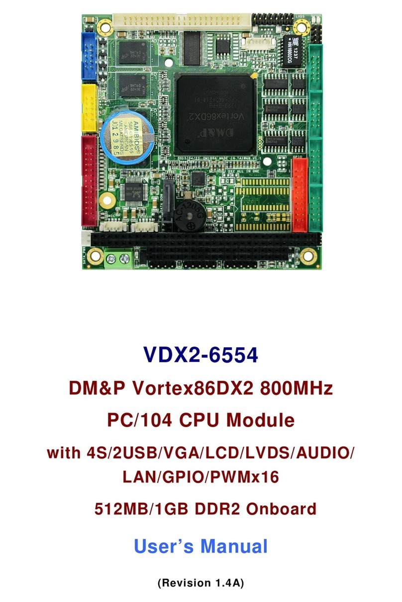
Thinklabs UNIBOARD V1.1 User manual

Open platform for Embedded and Real Time Systems Programming
TRI Technosolutions Pvt. Ltd.
THINKLABS
U
N
I
B
OARD V
Licensed by:
Open platform for Embedded and Real Time Systems Programming
TRI Technosolutions Pvt. Ltd.
OARD V
1.1
U
SER
G
UIDE
4/7/2009
Open platform for Embedded and Real Time Systems Programming
|

Thin LABS
© TRI Techn s luti ns Pvt Ltd Page 2 f 129 http://thinklabs.in
Table of Contents
Introduction ........................................................................................................................................................ 5
Pac age Contents ................................................................................................................................................. 6
Testing the Board ................................................................................................................................................. 7
Testing the B ard n Wind ws OS ............................................................................................................................... 7
Testing the B ard n Linux OS .................................................................................................................................... 11
What you need for programming the Board ........................................................................................................ 12
Hardware requirements .............................................................................................................................................. 12
S ftware requirements ............................................................................................................................................... 12
Safety and precauti ns t be taken ............................................................................................................................ 12
Pre-requisites .............................................................................................................................................................. 12
Hardware Connections ....................................................................................................................................... 13
Features ............................................................................................................................................................ 14
B ard Features ............................................................................................................................................................ 14
C ntr ller Features ..................................................................................................................................................... 15
Setting up the Board configuration ..................................................................................................................... 16
B ard Descripti n ....................................................................................................................................................... 16
Atmega128 c ntr ller ............................................................................................................................................. 16
Atmega8 c ntr ller with the firmware f r pr gramming thr ugh USB ................................................................. 16
I2C and RTC (DS1307) with Backup Battery ............................................................................................................ 16
Anal g sens rs (J ystick and LDR) .......................................................................................................................... 16
Buzzer ...................................................................................................................................................................... 16
Onb ard M t r Driver ............................................................................................................................................ 16
External p wer ........................................................................................................................................................ 17
Test LEDs ................................................................................................................................................................. 17
Tw UART's ............................................................................................................................................................. 17
LCD .......................................................................................................................................................................... 17
Push Butt ns ........................................................................................................................................................... 17
Selecti n Switches................................................................................................................................................... 17
General Purp se PORTS .......................................................................................................................................... 18
Jumper Settings ........................................................................................................................................................... 19

Thin LABS
© TRI Techn s luti ns Pvt Ltd Page 3 f 129 http://thinklabs.in
Software Installations ........................................................................................................................................ 22
S ftware Installati ns f r Linux OS ............................................................................................................................. 22
Text Edit r (Gedit Edit r) ........................................................................................................................................ 22
Installing Gedit Edit r: ............................................................................................................................................ 22
Gedit Edit r Plug-in (Embedded Terminal): ............................................................................................................ 24
C mpiler (avr-gcc) ................................................................................................................................................... 29
avr-libc (Standard C library f r Atmel AVR devel pment) : .................................................................................... 31
avrdude (s ftware f r pr gramming Atmel AVR micr c ntr llers): ...................................................................... 33
Serial p rt terminal (Gtkterm) ................................................................................................................................ 34
Gtkterm C nfigurati ns f r setting the Baud rate, Parity, St p bits ...................................................................... 37
S ftware Installati ns f r Wind ws OS ...................................................................................................................... 39
WinAVR (Includes avr-gcc, avr-binutils, avrdude) ................................................................................................... 39
Installing USB drivers f r uNiB ard ......................................................................................................................... 44
Programming the Board ..................................................................................................................................... 48
Getting Started n Linux ............................................................................................................................................. 48
Getting Started n Wind ws ...................................................................................................................................... 62
Text Edit r (pr grammer’s N tepad) ..................................................................................................................... 63
C mpile the c de and pr gram the b ard n Wind ws (C mmand Pr mpt) ....................................................... 67
Using hyper terminal f wind ws ........................................................................................................................... 75
Getting Started with RTOS (uC/OS-II) on Windows OS ......................................................................................... 79
uC/OS-II Hardware and S ftware Architecture .......................................................................................................... 79
C de, C mpile and pr gram the RTOS (uC/OS-II) pr grams n Linux OS .................................................................. 80
C de, C mpile and pr gram the RTOS (uC/OS-II) pr grams n Wind ws OS ............................................................ 89
Troubleshooting .............................................................................................................................................. 112
Make utility ............................................................................................................................................................... 112
LEDs ........................................................................................................................................................................... 112
UART.......................................................................................................................................................................... 112
LCD ............................................................................................................................................................................ 112
J ystick ...................................................................................................................................................................... 112
LDR ............................................................................................................................................................................ 113
External Interrupts .................................................................................................................................................... 113
RTC ............................................................................................................................................................................ 113
SPI .............................................................................................................................................................................. 113

Thin LABS
© TRI Techn s luti ns Pvt Ltd Page 4 f 129 http://thinklabs.in
M t r drivers ............................................................................................................................................................ 113
What you can do with the uNiBoard ................................................................................................................. 114
Add-ons ........................................................................................................................................................... 118
SD/MMC card Interface ........................................................................................................................................ 118
Ethernet Interface ................................................................................................................................................. 118
uNiBoard v1.1 Schematic ................................................................................................................................. 119
C ntr ller secti n: ATmega128 pin c nnecti ns ...................................................................................................... 119
Buzzer secti n ........................................................................................................................................................... 120
J ystick and c nnect rs secti n ............................................................................................................................... 120
LCD secti n ................................................................................................................................................................ 121
LDR secti n ................................................................................................................................................................ 121
LEDs secti n .............................................................................................................................................................. 121
M t r Driver secti n ................................................................................................................................................. 122
P wer supply secti n ................................................................................................................................................ 122
RTC secti n ................................................................................................................................................................ 122
Sens r p rt secti n ................................................................................................................................................... 123
Switches secti n ........................................................................................................................................................ 123
UART secti n ............................................................................................................................................................. 123
USB pr grammer secti n (C urtesy: http://www.fischl.de/usbasp/) ...................................................................... 124
Licensing terms ................................................................................................................................................ 125
Bill of Materials (BOM): .................................................................................................................................... 126
Appendix A – References .................................................................................................................................. 128
Appendix B - Services and Support ................................................................................................................... 129

Thin LABS
© TRI Techn s luti ns Pvt Ltd Page 5 f 129 http://thinklabs.in
Introduction
The uNiBoard version 1.1 is an ideal open source development platform f r Embedded and Real
Time Systems Programming. P wered by a RISC machine (ATMega128) that pr vides a thr ughput
f 16 MIPS and up t 128KB f internal st rage (flash), the b ard w uld be suitable f r any s rt f
embedded applicati n devel pment.
On-b ard peripherals like J ystick al ng with the c mmunicati n p rts (RS232) and the Gtkterm
driver (hyper-terminal f r Wind ws) make the b ard apt f r basic game devel pment in an
Embedded (n n-OS) as well as OS based envir nment. RT Kernels with small f tprint (uC/OS-II,
FreeRTOS, nut OS) can be p rted n the b ard t gain hands- n experience f Real time applicati n
design.
The b ard is p wered by the USB p rt. The b ard is als pr grammable thr ugh USB p rt thereby
making it c mplete stand-al ne lab equipment needing n thing apart fr m a basic PC/lapt p t get
started with the devel pment pr cess. The pen interface ( pen LED interface, pen p rts) extend
the platf rm’s r le f r pr t typing applicati ns like external device/sens r interfacing. The
c ntr ller by itself supp rts pr t c ls like SPI, I2C ( n-b ard I2C based RTC), UART (dual
pr grammable UART) which can be used f r multi-b ard c mmunicati n.
Additi nally, the b ard als features an n-b ard m t r driver which all ws t c ntr l up t tw
DC m t rs bidirecti nally. External supply, if required f r the m t rs can be pr vided with
appr priate hardware c nfigurati n settings.
The b ard al ng with its content-rich user manual is a perfect c mpani n t have f r
h bbyists/aspirants seeking a career in Embedded s ftware design, since it can acc mm date
preliminary applications like p rt c ntr l r sens r data pr cessing built on Embedded C t
complex real time applications built on RTOS like DAS (Data Acquisiti n Systems), embedded web-
server, FAT FS f r embedded systems and m re.
We plan t adhere t the Creative C mm ns license (Refer licensing terms), which has the
phil s phy f “Share, Remix, Reuse - Legally”. It means that any ne is all wed t pr duce c pies
f the b ard, t redesign it, r even t sell b ards that c py the design. Y u d n’t need t pay a
license fee t the Thin LABS team r even ask permissi n. H wever, if y u republish the reference
design, y u have t credit the riginal gr up. And if y u tweak r change the b ard, y ur new
design must use the same r a similar Creative C mm ns license t ensure that new versi ns f the
b ard will be equally free and pen.

Thin LABS
© TRI Techn s luti ns Pvt Ltd Page 6 f 129 http://thinklabs.in
Package Contents
The uNiB ard devel pment platf rm with the peripherals listed bel w
•uNiB ard devel pment b ard – 1 unit
•16x2 LCD – 1 unit
•Serial cable (DB9) – 1 unit
•USB cable – 1 unit
•FRC c nnect r cables – 2 units
•CD c nsisting f uNiB ard user manual (based n Linux (Ubuntu) /Wind ws), essential s ftware
packages and sample c des (RTOS/n n-OS applicati ns) – 1 unit
•P uch f r st rage – 1 unit

Thin LABS
© TRI Techn s luti ns Pvt Ltd Page 7 f 129 http://thinklabs.in
Testing the Board
This secti n lists the pr cedure t test the b ard. T enable y u t quickly test the B ard, it c mes with a
test pr gram l aded. S , make sure y u first test the b ard bef re any pr gramming.
If y u have pr grammed the c ntr ller thereby erasing the test pr gram fr m the flash r in case y u find
that the sample pr gram has n t been l aded (which w uld be a rare case) then y u need t l ad the test
pr gram nt the b ard (refer t the secti n Pr gramming the B ard). The test pr gram is pr vided n CD
uNiB ard C ntents direct ry (inside sample c des). This c de tests the b ard’s peripherals (LCD, UART,
LED’s, Buzzer, and J ystick).
Testing the Board on Windows OS
F ll w the steps t c nfirm if the uNiB ard is OK.
STEP 1: C nnect the LCD n the B ard (refer t secti n Hardware c nnecti ns).
STEP 2: Use FRC cable t c nnect pen LED p rt and P rt C.
STEP 3: Using the serial cable c nnect uNiB ard t the PC.
STEP 4: If y u are using Wind ws OS then y u need install the USB drivers f r the uNiB ard nce (refer t
the secti n S ftware Installati n >> S ftware Installati n f r Wind ws OS >> Installing the USB drivers f r
uNiB ard).
STEP 5: Using the USB cable c nnect the uNiB ard t the PC.
STEP 6: Turn ON the B ard nce the drivers are installed c rrectly.
STEP 7: Open the Serial terminal and set the baud rate t 115200, parity t n ne, and st p bits t 1. S click
n Start >> pr grams >> Pr grams >> Access ries >> C mmunicati ns >> hyper terminal as sh wn bel w.

Thin LABS
© TRI Techn s luti ns Pvt Ltd Page 8 f 129 http://thinklabs.in
STEP 8: Select File menu >> New C nnecti n then Enter Name f r c nnecti n and click OK.
STEP 9: Select the COM P rt where y u have c nnected the serial cable.

Thin LABS
© TRI Techn s luti ns Pvt Ltd Page 9 f 129 http://thinklabs.in
STEP 10: Select the settings as given bel w f r this test pr gram.
STEP 11: Select Apply and then OK.

Thin LABS
© TRI Techn s luti ns Pvt Ltd Page 10 f 129 http://thinklabs.in
STEP 12: Turn ON the B ard.
STEP 13: The test pr gram that we have l aded dem nstrates SNAKE game n any serial terminal which is
VT102 c mpatible. If everything is c rrectly installed y u sh uld be able t see a game f SNAKE (m dified)
as well as play using the J ystick.
While the pr gram is running y u will als be able t see the SCORE being displayed n the LCD al ng with
the versi n f the uNiB ard that y u are currently using. While the SNAKE eats up f d y u will be able t
hear the buzzer. Every time a new f d is generated y u will see the LEDs gl wing thereby utilizing all
uNiB ard peripherals.

Thin LABS
© TRI Techn s luti ns Pvt Ltd Page 11 f 129 http://thinklabs.in
Testing the Board on Linux OS
F ll w the steps t check whether r n t the uNiB ard is w rking pr perly n Linux OS
STEP 1: Step 1 t Step 3 is same as given in the Wind ws OS pr cedure.
STEP 2: Turn ON the B ard. If y u are w ndering h w t install the USB drivers, y u d n’t need t d that at
all since Linux kernel has th se drivers inbuilt.
STEP 3: Open the Gtkterm (refer to the sub-section Installing Software for Linux OS).
STEP 4: C nfigure the Gtkterm t baud rate/speed t 115200, parity t n ne, and st p bits t 1(refer t the
sub-secti n Gtkterm C nfigurati ns f r setting the Baud rate, Parity, St p bits).
STEP 5: Turn ON the B ard.
STEP 6: Out here as well y u sh uld be able t d things (like playing SNAKE n Gtkterm) that have been
listed in STEP 13.

Thin LABS
© TRI Techn s luti ns Pvt Ltd Page 12 f 129 http://thinklabs.in
What you need for progra ing the Board
Hardware require ents
•uNiB ard versi n 1.1 al ng with USB cable
•Serial cable ( pti nal)
•FRC Cable ( pti nal)
Software require ents
•Text Edit r (Gedit n Linux/ Pr grammers N tepad n Wind ws)
•T l chain (avr-gcc, avr-binutils, avrdude): Installati n pr cedure is explained in the upc ming
secti ns
•Serial terminal (Gtkterm n Linux/ hyper terminal n wind ws)
•Driver f r usbasp (Wind ws requires explicit installati n)
Safety and precautions to be taken
•D n t use the external p wer supply m re than 15V.
•B ard and SMD switches sh uld be handled with care.
•Fuse settings f the target (micr -c ntr ller) sh uld be m dified nly with appr priate
kn wledge, since l cking the fuse secti n might render the b ard useless.
•Do not pr gram the B ard while y u are using SPI lines f r c mmunicati n which might als
render the b ard useless.
Pre-requisites
•Bef re y u start, y u are expected t have s me kn wledge f AVR micr c ntr llers and its
s ftware t ls up t a preliminary level. We have n t discussed the AVR architecture (Datasheet
is the best help n the same. it has been included in the CD c ntents)
•The b ard guide d es n t give any c nceptual kn wledge with regards t RTOS. F r best results,
y u are expected t have a reference material n the RTOS that y u are g ing t use n the
b ard. In case the target RTOS is uC/OS-II, y u need n t l k bey nd MicroC/OS-II, The Real
Time Kernel by Mr. Jean Labrosse.
•All the samples examples based n RTOS including the SNAKE applicati n that y u must have
just seen while testing the b ard utilize the same RTOS kernel (i.e.: uC/OS-II)

Thin LABS
© TRI Techn s luti ns Pvt Ltd Page 13 f 129 http://thinklabs.in
Hardware Connections
The uNiB ard versi n 1.1 c nnects t the PC using USB p rt. As sh wn in the figure 1.1 n the b ard there is
a serial p rt and USB p rt c nnect rs. The serial p rt is used f r debugging purp se while USB p rt is used
f r p wer and burning the hex files int ATmega128 micr c ntr ller.
The USB cable (f r p wer/pr gramming purp ses) and serial cable can be interfaced with the PC. The serial
cable is pti nal as we are n t using it f r pr gramming the hex file int the Atmega128 chip. F r any UART
related activities having the serial cable is a must.
Pr gr
amming
Jumper
Pr gramming
c nnect r f r
USB
pr grammer
LDR
Jumper
8 Sens r
inputs
Pr gram
Enable/UART0
Selecti n
switch
USB p wer
switch
Test
LEDs
PORT
Ext P wer
C nnect r
UART 0
USB
P rt
Serial P rt
(UART 1)
M t r 1
M t r 2
J ystick/Ext. ADC
switch
Reset switch
ADC
PORT
JTAG
PORT
PORTC
USB
pr grammer
FRC
Cable
LD
R
RTC
RTC Backup
battery
LCD
c nnect r
J ystick
PORTG
c nnect r
8 LED’s
SW4, SW3,
SW2, SW1
switch i/p’s
4 SPI
Lines
Buzzer
beneath
C ntr ller
8 GND
lines
8 VCC
lines

Thin LABS
© TRI Techn s luti ns Pvt Ltd Page 14 f 129 http://thinklabs.in
Features
Board Features
•ATmega128 c ntr ller with external crystal f 16MHZ
•usbasp: ATmega8 based USB pr grammer f r ATmega128 ( pen s urce firmware running n
hardware licensed under GNU GPLv2 fr m http://www.fischl.de/usbasp)
•I2C c mmunicati n lines
•SPI c mmunicati n lines
•16x2 alphanumeric LCD with c ntrast adjustment
•RTC with Backup Battery
•Anal g J ystick with centre click
•LDR sens r
•Buzzer (beneath the pr cess r b ard)
•Onb ard M t r Driver (L293D)
•LEDs f r USB pr grammer ready indicat r, Pr gramming status indicat r, and P wer ON
indicat r
•Test LEDs ( pen f r interface with any PORT)
•Open interface P rts such as PORTF/ADC, PORTC
•JTAG interface(External JTAG hardware required)
•USB P rt f r pr gramming the B ard
•Dual pr grammable UARTs
•Push Butt ns f r External Interrupts, Reset
•C nfigurati n Switches f r USB P wer/External p wer, External ADC /J ystick and Pr gram
Enable/UART0
•M dular design t permit replacement f pr cess r b ard

Thin LABS
© TRI Techn s luti ns Pvt Ltd Page 15 f 129 http://thinklabs.in
Controller Features
The features f Atmega128 are as f ll ws:
•Advanced RISC Architecture
•128K Bytes f In-System Self-pr grammable Flash pr gram mem ry
•4K Bytes EEPROM
•4K Bytes Internal SRAM
•JTAG (IEEE std. 1149.1 C mpliant) Interface
•Tw 8-bit Timer/C unters with Separate pre-scaler and C mpare M des
•Tw Expanded 16-bit Timer/C unters with Separate pre-scaler, C mpare M de and
•Capture M de
•Real Time C unter with Separate Oscillat r
•Tw 8-bit PWM Channels
•6 PWM Channels with Pr grammable Res luti n fr m 2 t 16 Bits
•8-channel, 10-bit ADC
•Byte- riented Tw -wire Serial Interface
•Dual Pr grammable Serial USARTs
•Master/Slave SPI Serial Interface
•Pr grammable Watchd g Timer with On-chip Oscillat r
•P wer- n Reset and Pr grammable Br wn- ut Detecti n
•External and Internal Interrupt S urces
•Six Sleep M des: Idle, ADC N ise Reducti n, P wer-save, P wer-d wn, Standby, and Extended
Standby
•S ftware Selectable Cl ck Frequency (using Fuse bits)
•53 Pr grammable I/O Lines
•4.5V - 5.5V f r Atmega128 Operating V ltages
•64-lead TQFP

Thin LABS
© TRI Techn s luti ns Pvt Ltd Page 16 f 129 http://thinklabs.in
Setting up the Board configuration
Board Description
Atmega128 controller
The ATmega128 is a l w-p wer 8-bit micr c ntr ller based n the AVR enhanced RISC architecture. The
Atmel ATmega128 is a p werful micr c ntr ller that pr vides a highly flexible and c st effective s luti n t
many embedded c ntr l applicati ns.
Atmega8 controller with the firmware for programming through USB
USBasp is a USB in-circuit pr grammer f r Atmel AVR c ntr llers. It simply c nsists f an ATMega8 and a
c uple f passive c mp nents. The pr grammer uses a firmware (USB driver) t pr gram Atmega128
micr c ntr ller. F r m re inf rmati n n building USBasp refer http://www.fischl.de/usbasp. It is an pen
s urce firmware al ng with hardware licensed under GNU GPLv2.
I2C and RTC (DS1 07) with Backup Battery
The DS1307 serial real-time cl ck (RTC) is a l w-p wer, full binary-c ded decimal (BCD) cl ck/calendar plus
56 bytes f NV SRAM. Address and data are transferred serially thr ugh an I2C, bidirecti nal bus. The
cl ck/calendar pr vides sec nds, minutes, h urs, day, date, m nth, and year inf rmati n (C mpensati n
Valid up t 2100). N special hardware c nfigurati n is required as it is m unted n ur b ard and internally
c nnected t the pr cess rs pins.
Analog sensors (Joystick and LDR)
The J ystick (Anal g j ystick used in PS2 c ns les) is c nnected t the ADC, X axis n channel 1 (PF1) and Y
axis n channel 2 (PF2) f the Atmega128 micr c ntr ller. The LDR sens r is c nnected t channel 0(PF0) f
the Atmega128 micr c ntr ller.
Buzzer
The Buzzer is c nnected t PA3 f the Atmega128 micr c ntr ller, and lies beneath the pr cess r b ard.
Onboard Motor Driver
The M t r driver chip (L293D) is used t drive the m t rs which can be c nnected t the PTR c nnect rs as
sh wn in the ab ve figure. Thr ugh s ftware y u need t c nfigure as f ll ws:
PB6 and PB5 (MOTOR1)
PE2 and PE3 (MOTOR2)
PB4 (CHIP ENABLE)
There are m t rs which might need higher than 5V (up t 12V) perating v ltage. In such cases an external
supply can be given t the b ard and the USB p wer switch can be t ggled t make the external supply
available instead f a USB p wered c nnecti n.

Thin LABS
© TRI Techn s luti ns Pvt Ltd Page 17 f 129 http://thinklabs.in
External power
The external p wer c nnect r in the ab ve figure can als be used f r c nnecting rechargeable batteries
and making the b ard perate n battery p wer in case f r b tic r ther such m bile applicati ns.
Test LEDs
Test LED's are pulled-up s t glow the LEDs we need t make the particular p rt pin Low. Y u can c nnect
the General Purp se PORT t test LED P rt using FRC Cable.
Two UART's
UART1 is used t c nnect PC thr ugh the MAX232 v ltage c nverter chip since pc uses RS-232 standard f r
serial p rt. UART1 can be used f r debugging the c de r f r any s rt f interacti n with Gtkterm.
UART0 is n t c nnected t MAX232 as it is left pen f r c mmunicati n between tw B ards.
LCD
LCD f r uNiB ard is using 4 data lines, 2 c ntr l lines and WR f LCD is c nnected t GND.
DATA LINES (PA4, PA5, PA6, PA7)
CONTROL LINES (PA0 for RS, PA2 for LCD EN)
Push Buttons
External Interrupts
SW3 (INT6)
SW4 (INT7)
General Purp se switch
SW1 (PD6) Active Low
SW2 (PD7) Active Low
Reset SW
Selection Switches
USB P wer (Pressed) / External p wer (Depressed)
J ystick (Pressed) / External ADC (Depressed)
Pr gram Enable (Pressed) / UART0 (Depressed)
The most important part of board configuration is the configuration switches. More often than not,
programming errors or abnormal program response and execution are due to faulty configuration of
the switches. So, while programming, or using ADC, or external power supply or battery or while using
UART0 ma e sure you have first set the configuration switches in the correct position before
concluding that your program is not wor ing or the board is faulty.

Thin LABS
© TRI Techn s luti ns Pvt Ltd Page 18 f 129 http://thinklabs.in
USB P wer (Pressed) / External p wer (Depressed)
Refer t the uNiB ard figure where the c mp nents have been labeled t understand where these
switches are physically placed n the b ard. While y u have c nnected the uNiB ard cable f r
pr gramming purp ses r f r p wering the b ard this switch sh uld be in the pressed p siti n.
While c nnecting any external p wer supply r battery, this switch sh uld be in depressed p siti n.
This makes the 7805 v ltage regulat r c me int picture t pr vide 5V p wer supply f r the ICs.
J ystick (Pressed) / External ADC (Depressed)
While y u are using the anal g j ystick y u are using the internal ADC f the c ntr ller which is
available at PORTF (Channel 1 – X axis and Channel 2 – Y axis). The LDR which is an ther anal g
sens r is als c nnected at PORTF (Channel 0). Make sure that this switch is in pressed p siti n
while the j ystick is being used.
In case y u want t use the pen interface pins f the PORTF, in rder t c nnect external anal g
sens rs r digital sens rs (refer labeled figure f uNiB ard), change the switch p siti n t
depressed. There is an ther jumper setting which y u w uld need t d in rder t take the LDR ut
f the circuit. This c nfigurati n will be discussed while discussing jumper settings.
Pr gram Enable (Pressed) / UART0 (Depressed)
While pr gramming the b ard this is ne switch that y u sh uld never f rget t press, failing which
avrdude (pr gramming s ftware will flash an err r saying “target n t f und”.
Once pr gramming has been c mpleted in rder t gain access t UART0 y u will need t keep the
switch in the depressed p siti n, since the UART0 pins are multiplexed with the pr gramming pins.
General Purpose PORTS
PORTC
PORTC is an pen interface p rt which can be used t c nnect any devices n FRC c nnect r.
PORTF (J ystick/LDR/External sens rs)
PORTF can be used t c nnect external anal g r digital sens rs r it can als be used as J ystick r LDR ADC
channels. There are tw c nnect rs FRC c nnect r and Berg sens r p rt c nnect r either f which can be
used t c nnect the external sens rs. The Berg sens r p rt c nnect r is c mpatible with ur TRI sens rs.
Y u can visit t website at http://www.thinklabs.in/res urces/ t check ut TRI sens rs and y u can buy at
http://www.thinklabs.in/sh p/.
PORTG
PORTG is an pen interface p rt which can be used t c nnect any devices n berg c nnect r.
PORTC and PORT F

Thin LABS
© TRI Techn s luti ns Pvt Ltd Page 19 f 129 http://thinklabs.in
The PORTC and PORTF (ADC) are pen p rts and can be c nnected t test LEDs thr ugh FRC cable. These can
be accessed using 10-pin the FRC c nnect r.
The pin diagram f Atmega128 is given bel w al ng with the manner in which we have utilized the p rt pins
in case f uNiB ard:
Ju per Settings
Apart from the configuration switches discussed above the jumper settings is another source of arriving to
wrong conclusions provided that they have not been set correctly.
SPI
lines
LCD
DATA
UART0
1
I2C
(RTC)
PORTC
(Open
Interface n
FRC
c nnect r)
UART1
(Max232)
16 MHz
Crystal
MOTOR 2
MOTOR 1
MOTOR EN
J ystick/LDR/Ex
ternal sens rs
LCD RS
LCD EN

Thin LABS
© TRI Techn s luti ns Pvt Ltd Page 20 f 129 http://thinklabs.in
There are tw jumpers n the b ard ne f r pr gramming r SPI jumper and ther ne f r LDR r External
ADC selecti n. As sh wn in the figure bel w:
LDR jumper
Y u can use them as per y ur applicati n requirements. In case y u are c nnecting external sens rs at the
sens r p rt, y u will need t change the p siti n f the LDR jumper s as t disass ciate it fr m the circuit
as sh wn bel w:
LDR
Jumper
4 SPI
Lines
Pr gramming
Jumper
J ystick/External
sens r Selecti n
USB P wer
Selecti n
Pr gram Enable
/UART0 Selecti n
Table of contents

