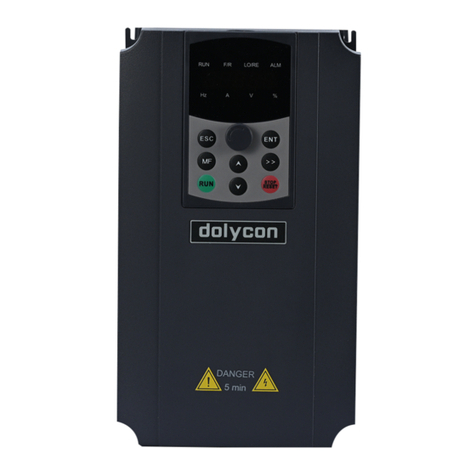
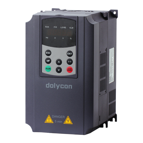
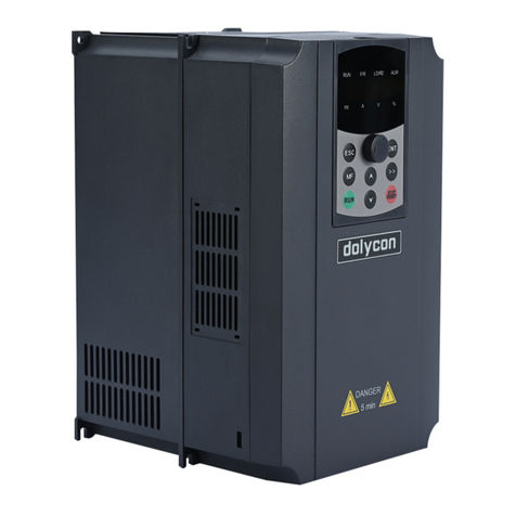
dolycon CT120G MINI Series User manual


CT120G Mini Series Inverter Preface
- 1 -
Preface
Thanks for choosing CT120G mini series inverter. Please this manual
carefully before using. If you find any problem or not understand this
manual, please contact factory. If any problem in using, please also
contact engineer of factory also. We will keep to updated both hardware
and software to get better performance without notice. Please understand.
Document version: V1.0

CT120G Mini Series Inverter Preface
- 2 -

CT120G Mini Series Inverter Content
- 3 -
Content
1 Product Infirmation.............................................................................5
2 Instal and Wire..................................................................................9
3 Parameter Table.................................................................................14
Appendix 1 Communication Address...................................................64
Appendix 2 Troubleshooting List. .......................................................68
Product Certification...............................................................................75
Guarantee..................................................................................................76

CT120G Mini Series Inverter Content
- 4 -

CT120G Mini Series Inverter 1 Product Infirmation
- 5 -
1 Product Infirmation
Model
Model
Power
(KW)
Input
current
(A)
Output
current
(A)
Motor power
(KW)
Single phase 220Vac 50/60Hz
CT120G-2S-0.7-B
0.75
8.2
4.5
0.75
CT120G-2S-1.5-B
1.5
14.0
7.0
1.5
CT120G-2S-2.2-B
2.2
23.0
9.6
2.2
Three phase 380Vac 50/60Hz
CT120G-4T-0.7-B
0.75
3.4
2.5
0.75
CT120G-4T-1.5-B
1.5
5.0
3.7
1.5
CT120G-4T-2.2-B
2.2
5.8
5.3
2.2
Technic table
Input and
output
parameters
Input voltage
Single-phase 220VAC±15%,
three-phase 380VAC±15%,.
Input frequency
50~60Hz±5%
Output voltage
0~Rated input voltage
Output
frequency
0~500Hz
Overload
capacity
150% of rated current: 60s; 180% of
rated current: 10s; 200% of rated current:
1s
Technical
control
parameter
s
Control mode
V/F control, sensorless vector control
Speed ratio
Open loop vector control 1:200; V/F 1:
100
Speed control
accuracy
±0.5%
Speed wave
±0.5%
Start torque
0.5Hz/150%(V/F)
0.25Hz/150% (SVC)

CT120G Mini Series Inverter 1 Product Infirmation
- 6 -
Based functions
Starting
frequency
0.00
~
10.00Hz
ACC and DEC
time
0.1
~
65000.0s
Carrier
frequency
0.5KHz
~
16.0KHz
Frequency
setting
UP/DOWsetting,Analog setting, digital
setting, multi-step speed setting, PID
setting, MODBUS communication setting
Start mode
Start frequency, DC braking and start
Stop mode
DEC stop, free stop, DEC
+DC braking
Energy braking
capability
Braking unit braking voltage:320
~
750V
DC braking
capability
DC braking frequency: 0~500Hz;
DC braking waiting time: 0~10s;
DC braking current: 0.0~100.0%;
DC braking time: 0.0~100.0s;
Auto voltage
adjustment
Keep a stable voltage automatically when
the grid voltage transients
Sudden
frequency down
Keep stable bus voltage while power net
low-voltage
Control
terminals
Digital input
Standard 5-channel inputs, one of which
can be high-speed pulse input (HDI)
Analog input
Standard 2-channel inputs, AI1,AI2: 0~
10V or 4 ~20mA input optional by
F03.34
Digital output
Standard 2-channel multi-function
collector outputs, one of which can be
high-speed pulse output (HDO).
Relay output
Standard 2-channel relay outputs
Communication
Communication
communication interface for external

CT120G Mini Series Inverter 1 Product Infirmation
- 7 -
interface
communication.
Fault protection
ACC overcurrent, DEC overcurrent, constant speed
overcurrent, ACC overvoltage, DEC overvoltage,
constant speed overvoltage, bus under voltage, motor
overload, inverter overload, input power failure, output
phase loss, rectifier module overheating, inverter module
overheating, external fault, communication fault, current
detection fault, EEPROM operation fault, PID feedback
fault, factory setting time arrive etc.
Keypad display
LED display
Highlight LED digital tube displays the
inverter information
Others
Running
environment
Indoors, less than 1km above sea level,
without dust, corrosive gases or direct
sunlight
Ambient
temperature
-10 ~+40℃, derate 1% for every
additional 1℃when the ambient
temperature is between 40~50℃
Humidity
5~95% (no condensation)
Altitude
0~2000m, derate 1% for every
additional 100m when the sea level is
above 1000m
Vibration
Less than 0.5g
Storage
temperature
−40~+70℃

CT120G Mini Series Inverter 1 Product Infirmation
- 8 -
Size of inverter and keypad
Model
Size(mm)
Mounting
hole size
(mm)
Weight
(kg)
W
W1
H
H1
D
CT120G-2S-0.7-B
84.6
67.3
170.2
159.8
131
5.5
1.2
CT120G-2S-1.5-B
CT120G-2S-2.2-B
CT120G-4T-0.7-B
CT120G-4T-1.5-B
CT120G-4T-2.2-B
Keypad wire can not more than 30m

CT120G Mini Series Inverter 2 Instal And Wire
- 9 -
2 Instal and Wire
Systerm parts suggested
Model
Main wire
(copper,
m2)
Brake
rated
current
(A)
Contactor
rated
current
(A)
Braking resistor
Power
(kW)
Resist
(Ω)
CT120G-2S-0.7-B
2.5
16
10
≧0.3
≧200
CT120G-2S-1.5-B
4
20
16
≧0.3
≧150
CT120G-2S-2.2-B
4
32
25
≧0.3
≧85
CT120G-4T-0.7-B
2.5
10
10
≧0.3
≧320
CT120G-4T-1.5-B
2.5
16
10
≧0.3
≧250
CT120G-4T-2.2-B
2.5
16
10
≧0.3
≧150
Main terminals
Terminal name
Function
R、S、T
3phase power input
L、N
2phase power input
(+)、PB
Connect braking resistor
U、V、W
3phase output
Earth terminal (PE)
Control board terminals
Type
Terminal
name
Function
Specification
Digital input
+24V
+24V power
24V±10%, isolated to

CT120G Mini Series Inverter 2 Instal And Wire
- 10 -
Type
Terminal
name
Function
Specification
GND
DI1~DI4
Digital input
terminals 1~4
Input specification:24V,
5mA
HDI
high-speed
pulse input or
digital input
Pulse input frequency
range:0~20KHz
High power level
voltage:24V
COM
+24V power or
out power
Isolated to GND
Digital output
DO
Collector
outputs, public
termial COM
Out connect voltage:0~
24V
HDO
High-speed
pulse output or
collector
outputs, public
termial COM
Pulse output frequency
range:0~50KHz
COM
DO,HDO
public terminal
Isolated to GND
Analog input
+10V
+10V output
support
Output voltage:10V,
output current range:0~
50mA
(If potentiometer
connected between +10V
and GND, resist of
potentiometer should not
be lower than 2k)
AI11~AI2
Analog input
terminal
Input voltage selection
Input voltage range:0V~
10V
Input current range:0/4~
20mA
GND
Analog earth
Isolated to GND
Analog output
AO1~AO2
Analog output
terminal
Output voltage selection
Output voltage

CT120G Mini Series Inverter 2 Instal And Wire
- 11 -
Type
Terminal
name
Function
Specification
range:0V~10V
Output current
range:0/4~20mA
GND
Analog earth
Isolated to GND
Relay output
T1A/TIB/TIC
Relay output
T1A-T1B:always close
T1A-T1C:always open
Contractor
capability:250VAC/3A,
30VDC/1A
T2A/T2B/T2C
Relay output
T2A-T2B: always close
T2A-T2C:always open
Contractor
capability:250VAC/3A,
30VDC/1A
Communication
interface
485+/485-
communication
interface
communication interface
Indicator and buttons on keypad
Symbol
Name
meaning
Unit LEDs
Hz
Frequency LED
The unit of the current displayed
parameter is Hz.
A
Current LED
The unit of the current displayed
parameter is A.
V
Voltage LED
The unit of the current displayed
parameter is V.
%
Percentage LED
The current displayed parameter is a
percentage.
Status LEDs
RUN
Run status LED
On: The inverter is running.
Off: The inverter stopped.
Blinking: The inverter is in dormant state.
F/R
Forward/Reverse
LED
On: The inverter is in the reverse running
state.
Off: The inverter is in the forward running
state or stopped.
LO/RE
Run command
Off: keypad run command reference mode

CT120G Mini Series Inverter 2 Instal And Wire
- 12 -
Symbol
Name
meaning
reference LED
Blinking: terminal run command
reference mode
On: communication run command
reference mode
TUNE
Self
identification /
Alarm LED
Off: no fault alarm
Quick blinking: fault alarm
Slow blinking: motor under self
identification
On: torque control mode
Button
Name
Function
Programming/
Exit key
Enter or exit the 1st level menu;
Return to the 1st level menu from the 2nd
level menu;
Return to the 2nd level menu from the 3rd
level menu.
Multi-function
key
Operate according to multi-function selection
[2]
Run key
In the keypad run command reference mode,
the key is used for start control of the
inverter.
After setting the parameter self-identification,
the key is used to start the inverter for
parameter self-identification.
Enter key
After function group confirmation of the 1st
level menu, enter the 2nd level menu;
After function group confirmation of the 2nd
level menu, enter the 3rd level menu;
After function parameters setting
confirmation of the 3rd level menu, return to
the 2nd level menu;
In password verification state, the password
input is completed.

CT120G Mini Series Inverter 2 Instal And Wire
- 13 -
Right-shift key
Function group edit step[1] selection in the
1st/2nd level menu;
Function parameters settings edit step
selection in the 3rd level menu;
In stop parameter display status, running
parameter display status and fault display
state, display parameters selection;
Edit bit selection in password verification
state.
Stop/Reset key
In keypad run command reference mode, the
key is used for stop control of the inverter;
In other run command reference modes, the
key is used for stop protection of the
inverter[3];
At fault or stop state, the key is used as a
reset key to clear the fault alarm information.
UP key
Increase function group in the 1st/2nd level
menu progressively;
Increase function parameters settings in the
3rd level menu progressively;
Increase the set frequency progressively.
DOWN key
Decrease function group in the 1st/2nd level
menu progressively;
Decrease function parameters settings in the
3rd level menu progressively;
Decrease the set frequency progressively.
Potentiometer
Adjust the frequency;
Adjust the torque.

CT120G Mini Series Inverter 3 Parameter Table
- 14 -
3 Parameter Table
Function
code
Name
Detailed instruction of
parameters
Default
value
Attribu
-tion
F00 Group Basic function
F00.00
Motor control
mode
0:speed sensorless vector
control
1:reserved
2:V/F control
2
☆
F00.01
Run command
channel
0: keypad run command
channel (LED off)
1: terminal running command
channel (LED on)
2: 485 run command channel
(LED flickering)
0
○
F00.02
Main frequency
source X
0:Digital setting( pre-set
frequency F00.09,UP/DOWN
change, no power down
memory)
1:Digital setting( pre-set
frequency F00.09,UP/DOWN
change, with power down
memory)
2:AI1
3:AI2
4:keypad potentiometer AI0
5:high speed pulse input(DI5)
6:multi-step speed
7:simple PLC
8:PID
9:485 communication
0
☆
F00.03
Auxiliary frequency
source Y
Same as F00.02main
frequency
0
☆
F00.04
Reference object of
Y frequency source
0: relative to the max.
frequency
1: relative to frequency
source X
0
○
F00.05
Frequency source
Unit: frequency source
00
○

CT120G Mini Series Inverter 3 Parameter Table
- 15 -
Function
code
Name
Detailed instruction of
parameters
Default
value
Attribu
-tion
selection
selection
0: main
1: main and auxiliary
operation ( decided by ten)
2: main<--> auxiliary
3: main<-->main and
auxiliary operation
4:auxiliary<-->main and
auxiliary operation
Ten: main and auxiliary
operation relationship
0:main + auxiliary
1:main- auxiliary
2:max
3: min
F00.06
Max. frequency
50.00Hz
~
500.00Hz
50.00
☆
F00.07
Upper limit
frequency
F00.08~F00.06 (Max.
frequency)
50.00
○
F00.08
Lower limit
frequency
0.00Hz~F00.07 (upper limit
of running frequency)
0.00
○
F00.09
Frequency
pre-setting
0.00Hz~F00.06 (Max.
frequency)
50.00
○
F00.10
Run direction
0: positive
1: reverse
0
○
F00.11
Carrier frequency
0.5kHz
~
16.0kHz
6.0
○
F00.12
Carrier frequency
adjusted according
to temperature
0:no
1:yes
1
○
F00.13
Motor selection
0:motor 1
1:motor 2
0
☆
F00.14
ACC time 1
0.00s
~
650.00s(F00.16=2)
0.0s
~
6500.0s(F00.16=1)
0s
~
65000s(F00.16=0)
20.0
○
F00.15
DEC time 1
0.00s
~
650.00s(F00.16=2)
20.0
○

CT120G Mini Series Inverter 3 Parameter Table
- 16 -
Function
code
Name
Detailed instruction of
parameters
Default
value
Attribu
-tion
0.0s
~
6500.0s(F00.16=1)
0s
~
65000s(F00.16=0)
F00.16
Unit of ACC/DEC
time
0:1s
1:0.1s
2:0.01s
1
☆
F00.17
Auxiliary frequency
source Y range
0%
~
150%
100
○
F00.18
Upper limit
frequency source
0:F00.07set
1:AI1
2:AI2
3:keypad potentiometerAI0
4:high speed pulse input
5:485 communication
0
☆
F00.19
Upper limit
frequency offset
0.00Hz
~
max
frequencyF00.06
0.00
○
F00.20
Superimposed
auxiliary frequency
source offset
0.00Hz
~
max
frequencyF00.06
0.00
○
F00.21
Decimal point of
frequency
instruction
1:0.1Hz
2:0.01Hz
2
☆
F00.22
Digital setting
frequency memory
selection
0: save memory
1:not save memory
0
○
F00.23
Basis frequency of
ACC/DEC time
0:Max frequency
(
F00.06
)
1:setting frequency
2:100Hz
0
☆
F00.24
Basis frequency of
running
frequencyUP/DOW
N
0:running frequency
1:setting frequency
0
☆
F00.25
Command source
binding frequency
source
Unit: keypad command,
binding frequency source
selection
0: no binding
000
○

CT120G Mini Series Inverter 3 Parameter Table
- 17 -
Function
code
Name
Detailed instruction of
parameters
Default
value
Attribu
-tion
1: digital setting frequency
2:AI1
3:AI2
4:keypad potentiometer AI0
5:high speed pulse input
(DI5)
6:multi-step speed
7:simple PLC
8:PID
9:485 communication
Ten: Terminal command
binding frequency source
selection
Hundreds:communication
command binding frequency
source selection
F00.26
Serial
communication
protocol selection
0:Modbus-RTU protocol
1:reserved
0
☆
F01 Group Motor 1 parameters
F01.00
G/P type
0:G type
1:P type
0
☆
F01.01
Motor type
0: normal asynchronous
motor
1: change frequency
asynchronous motor
0
☆
F01.02
Rated power of
asynchronous
motor
Depend on model
☆
F01.03
Rated frequency of
asynchronous
motor
0.01Hz
~
(Max.
frequency)F00.06
50.00
☆
F01.04
Rated speed of
asynchronous
motor
1rpm
~
65535rpm
1460
☆

CT120G Mini Series Inverter 3 Parameter Table
- 18 -
Function
code
Name
Detailed instruction of
parameters
Default
value
Attribu
-tion
F01.05
Rated voltage of
asynchronous
motor
1V
~
2000V
380
☆
F01.06
Rated current of
asynchronous
motor
0.01A
~
655.35A
9.00
☆
F01.07
Stator resistance of
asynchronous
motor
0.001Ω
~
65.535Ω
1.204
☆
F01.08
Rotor resistance of
asynchronous
motor
0.001Ω
~
65.535Ω
0.908
☆
F01.09
Inductance of
asynchronous
motor
0.01mH
~
655.35mH
5.28
☆
F01.10
Mutual inductance
of asynchronous
motor
0.1mH
~
6553.5mH
158.6
☆
F01.11
Non-load current
of asynchronous
motor
0.01A
~
F01.03
4.24
☆
F01.12
Motor parameters
autotuning
0: no actuation
1: dynamic autotuning 1
2: static autotuning
3: : dynamic autotuning
0
☆
F02 Group Start and stop control
F02.00
Start mode
0: start at the starting
frequency
1: start after rotating speed
tracking
2: Pre excitation
0
○
F02.01
Start delay time
0.0s
~
1000.0s
0.0
○
F02.02
Starting frequency
0.00Hz
~
10.00Hz
0.00
○
F02.03
Hold time of
starting frequency
0.0s
~
100.0s
0.0
☆
This manual suits for next models
6
Table of contents
Other dolycon Inverter manuals