Zamp Solar ZS-8AW User manual

Solar Controller / Battery Charger
Input: DC12/ 24 Volt Solar Panel (Max. 50V)
Output: DC 12/ 24V 8A
Model Number: ZS-8AW
User’s Manual

2
FEATURES
●12 Volt or 24 Volt system compatible, auto-detecting.
●Advanced MCU-controlled pulse width modulated (PWM)
technology for high efficiency operation.
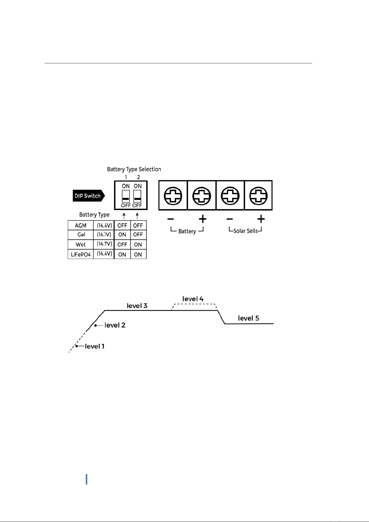
●Functions with Gel, AGM, Conventional lead-acid (WET) or
LiFePO4(LFP) Batteries, user selected via DIP switch.
●Built-in regulator to prevents battery from being overcharged or
undercharged. Overcharging occurs when the charge voltage is
unregulated. This can result in premature battery failure.
●The unit provides an automatic equalization feature for a deeply
drained conventional lead-acid battery.
●Can be connected to the battery permanently to keep the
battery fully charged by using a process called “floating”. This
means the controller will stop charging when the battery is full
and will automatically start charging the battery as required. This
process will also reduce water loss and help prevent the battery
from ‘drying out’.
●Protects the battery from discharge at night. Under low light or
no light conditions the solar panel voltage could be less than the
battery voltage. The unit contains a special circuit which
prevents current flowing back from the battery to the solar
panel.
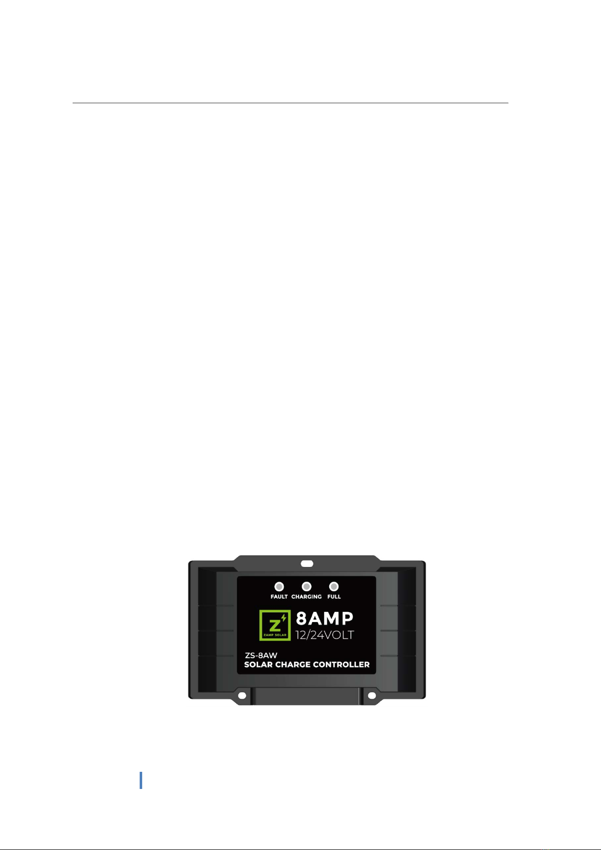
●Colored LED’s indicate charging status, battery condition and
system fault
●Multi-charging protections against reverse polarity, short circuit,
over temperature, over voltage, etc.
●Conformal-coating circuit boards and plated terminals protect
from hostile environments.
●Waterproof with IP67 rating.
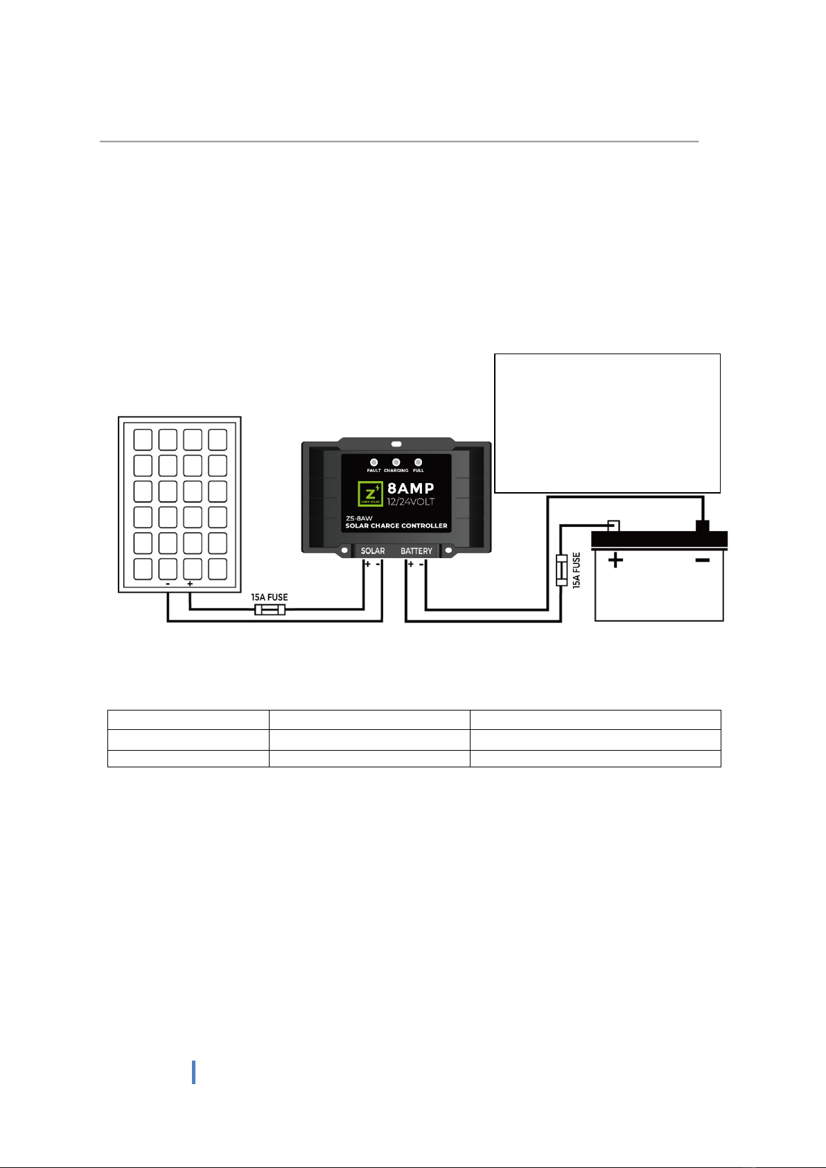
For use with 12V or 24V solar panels up to 270 Watts

3
WARNING -- IMPORTANT PLEASE READ
This charger is designed for indoor or outdoor use.
Do not disassemble the controller. Contact Zamp Solar Tech
Support if the unit requires repair.
Lead acid batteries can be dangerous. Ensure no sparks or
flames are present when working near batteries.
Eye protection should always be used.
Never short circuit the battery.
Given sufficient light, solar panels will generate energy even
when they are disconnected. Cover the panels with cloth or
cardboard to block all incoming light during the installation. This
will ensure that no damage is caused to the solar panel or
battery if the wires are accidentally short circuited.
Accidental ‘shorting’ of the terminals or wiring can result in
sparks causing personal injury or a fire hazard.
Always install a fuse on each circuit including the solar controller.
Do not reverse connect the wires to the solar panel or battery.
MOUNTING THE DEVICE
The Solar Controller is mounted as below
The quickest and easiest way to mount the unit is on a flat surface
using the three plastic spacers and self-tapping screws supplied.
Figure 1.1

4
WIRING CONNECTIONS
To protect the Battery and the Solar Panel, we strongly recommend that you
place a 15A inline fuse on the positive wire on both the “Solar” and “Battery”
Circuits. (As close to the battery/ panel as possible). Cover up the panel(s) with
cloth or cardboard to block all incoming light during the installation.
The Solar Controller has 4 terminals which are clearly marked ‘Solar’ and ‘Battery’.
There is a (12/ 24V) and earth (GND) terminal for each circuit.
Refer to the wiring diagram below.
Figure 2.1
Battery Connection
Solar Array Connection
Length of Wire
5ft 10ft
10ft 15ft 20ft
Size (AWG)
14 12
14 12 12
1. Insert the positive (+) and negative (-) wires from the solar panel to the
“Solar” terminal on the back of the controller and tighten screws firmly.
2. Insert the positive (+) and negative (-) wires from the battery to the
“Battery” terminal on the back of the controller and tighten screws firmly.
3. Double check the positive (+) and negative (-) wiring orientation before
uncovering the solar panel.
When the connections are completed, the Solar Controller will start working
automatically.
Correct Wire Size:
Please refer to the wire size
chart below to determine the
minimum size wire needed for
each connection. This will also
ensure you get the best
performance out of your solar
regulator.

5
BATTERY TYPE SETTING - via DIP switch
Please check your battery manufacturer’s specifications to select the correct
battery type. The unit provides for 4 battery types: Gel, AGM, WET (conventional
lead acid), and LiFePO4.
There is a DIP switch at the back of the solar charge controller, this Dip switch is
used for presetting your battery type. Please refer to Figure 3.1 to make DIP
switch setting for the proper battery chemical; the factory default setting is AGM
battery type.
Note: Once the Dip switch setting is finished, do not change the DIP switch
unless disconnected from the battery; otherwise it may damage your battery.
The unit has a 5-stage charging algorithm.
Soft Charge (Level 1) – Bulk Charge (Level 2) – Absorption charge (Level 3) –
Equalizing Charge* (Level 4) - Float Mode (Level 5)
Figure 4.1
Soft Charge When a battery suffers an over-discharge, the controller
will softly ramp the battery voltage up to 10V.
Bulk Charge Maximum current charging until the battery rises to the
Absorption level.
Absorption Charge Constant voltage charge when the battery is over 85%.
Equalization Charge* Only for WET battery, when the battery is deeply drained
below 11.5V, it will automatically run this stage to bring
the internal cells to an equal state to reduce any loss of
capacity.
Float Charge Battery is fully charged and maintained at a safe level
Voltage values are for 12V system, x 2 for 24V system

6
OPERATION - L.E.D. INDICATION
The 3 LED’s indicate the
charging status and Fault
connection
Fault Charge Full
Red Blue Green
Solar Power Present-No
battery connected
ON Slow flash Slow flash
Battery reversed
ON
Fast flash
Fast flash
Solar panel reversed
OFF
OFF
OFF
Soft start charging
OFF
Slow flash
OFF
Bulk, Absorption,
Equalization charging
OFF ON OFF
Float charging OFF OFF ON
Solar panel weak Slow flash OFF OFF
At night, no charge OFF OFF OFF
Slow flash = 1Hz flash; Fast flash = 3 Hz flash

7
SPECIFICATIONS
1
Electrical Parameters
1-1
Rated solar panel amps
8
Max.
AMP
1-2
Normal input Solar cell array voltage
15-22
VDC
1-3
Max. solar cell array voltage (output has no load)
25
Max.
VDC
1-4
The controller lowest operating voltage (at solar or
battery side)
9V
Min
VDC
1-5
Standby current consumption at night
2
Max
mA
1-6
Maximum voltage drop-Solar panel to battery
0.25
Max.
VDC
2
Charging characteristics
2-1
Minimum battery start charging voltage
3
Min
VDC
2-2
Soft start charging voltage
3-10
+/ -0.2
VDC
2-3
Soft start charging current (50%PWM duty)
Up to 4
AMP
2-4
Bulk charge voltage
10-14.0
+/ -0.2
VDC
2-5
Absorption charging voltage at 25
℃
--Gel type battery
14.1
+/ -0.2
VDC
--AGM type battery (default setting)
14.4
+/ -0.2
VDC
--WET type battery
14.7
+/ -0.2
VDC
--LiFePO4 type battery
14.4
+/ -0.2
VDC
2-6
Absorption transits to Equalizing or Float condition:
--Charging current drops to
0.8
+/ 0.1
AMP
-- or Absorption charging timer timed out
4
Hour
2-7
Equalization charging active (Only for WET)
--Battery voltage discharged to less than
11.5
+/ -0.2
VDC
2-8
Equalization charging voltage at 25
℃
15.5
+/ -0.2
VDC
2-9
Equalization charging timer timed out
2
Hour
2-10
Float charging voltage at 25
℃
-- for GEL, AGM and WET battery
13.6
+/ -0.2
VDC
-- for LiFePO4 battery
13.4
+/ -0.2
VDC
2-11
Battery temperature compensation coefficient
-24
mV/ °C
2-12
Temperature compensation range
-20 ~
+50
°C
3
Protection
3-1
Against reverse polarity or short circuit at panel side
3-2
Against reverse polarity or short circuit at battery
side
3-3
No reverse current from battery to solar at night
3-4
Over temperature protection during charging
65
°C
4
Electrical parts
4-1
Input output terminal
M4 terminals
4-2
Temperature sensor port or DIP switch
5
Physical Parameters
5-1
Controller material
Plastic, Standard ABS
5-2
Power terminal maximum stranded wire size
#12AWG stranded-3 mm2
5-3
Mounting
Vertical wall mounting
5-4
IP grade
IP67,
5-5
Net weight
Approx. 0.2kg / 0.44lb
6
Environmental characteristics
6-1
Operating temperature
-25 ~ 50°C / -13~122°F
6-2
Storage temperature
-40 ~ 85°C / -40~185°F
6-3
Operating Humidity range
100%no condensation
Voltage values are for 12V system, x 2 for 24V system
Table of contents
Other Zamp Solar Inverter manuals
Popular Inverter manuals by other brands

Generac Power Systems
Generac Power Systems QUIET TEST 5418 Specification sheet

Northern Lights
Northern Lights M673LD3 Assembly instructions

Westerbeke
Westerbeke 4.5BCG Operator's manual

Carbest
Carbest 82282 instruction manual

Goodwe
Goodwe SUNSHINE TILE installation manual

Growatt
Growatt SPF 4KT HVM user manual

SpectraDynamics
SpectraDynamics HROG-5 operating manual

Generac Power Systems
Generac Power Systems 000595-1 owner's manual

Bosch
Bosch FCB 120-1V-NB User manual & installation guidelines

MPP Solar
MPP Solar 1KVA-5KVA user manual

HiQ Solar
HiQ Solar TrueString TSXL380-8k-VN Installation & operator's manual

SMA
SMA SUNNY TRIPOWER 5000TL operating manual