THM Carbones Clavicula SE User manual

INSTRUCTION BOOK
t h m . b i k e


T H M
C L A V I C U L A S E
Don’t forget that your THM component is a lightweight carbon design.
Be aware of this when carrying out assembly and maintenance work and when
handling the component. Proceed with utmost care!

LOREM
T H M
C L A V I C U L A S E
CONTENT
CONTENT
CONTENT ............................................... 4
INTRODUCTION
.................................. 5
Preface
................................................................... 5
SAFETY
................................................. 6
Intended use
........................................................ 6
Fundamental safety precautions
................. 6
Assembly & Maintenance
................................. 7
On the road
........................................................... 8
Transport & Storage
..........................................8
SPECIFICATIONS
............................... 9
Scope of delivery
............................................... 9
Size
........................................................................ 10
THM Bottom Bracket
...................................... 11
Tightening Torques
......................................... 14
Application area
................................................ 14
INSTALL
..............................................15
General Information
........................................ 15
Preparing the Frame
....................................... 16
Bottom bracket install
.....................................17
Chainring install
................................................22
Installing the crankset .......................................23
Adjusting the bottom bracket
.....................25
Installing the pedals
...................................... 27
Finish touch.......................................................... 27
DISASSEMBLY
.................................. 28
Crankset................................................................28
Bottom bracket....................................................29
MAINTENANCE
................................. 32
Important maintenance information
........32
Disposal
...............................................................33
Before every journey
......................................34
Checking bottom bracket clearance
........34
Regular maintenance
.....................................35
Liability for defects
......................................... 37
Fair deal promise
................................................37
Crash Replacement
.........................................37

LOREM
T H M
C L A V I C U L A S E
5
INTRODUCTION
INTRODUCTION
Preface
This manual is an integral part of your THM component and it provides you with information
regarding the safe operation of your THM-Clavicula crank system.
Read this manual carefully prior to assembling your THM component. Always read and
observe all of the assembly and maintenance instructions in this manual, as well as those
provided inthe manuals of other manufacturers whose products are used on your bicycle (e.g.
framchainwheels, pedals,etc.).
Non-observance of the information contained in this manual could result in an accident and
death or serious injury.
You will encounter the following symbols and references in this manual:
The arrow indicates the consequence of your action.
This safety message indicates a hazardous situation which,
if not avoided, could result in death or serious injury.
This message warns of a risk of material damage.
This refers to additional information or tips.
Retain this manual for other users of your THM components. Make sure that all users read,
understand and observe this manual. If you ever sell or give away your THM components, this
manual should be transferred to the new owner.
We hope you get a lot of joy from your THM components!
Your THM-Carbones Team
WARNING
NOTICE
INFO
WARNING

LOREM
T H M
C L A V I C U L A S E
6
SAFETY
SAFETY
Intended use
Any use differing from that intended could cause an accident and result in death or
serious injury.
THM-Clavicula crank systems have been exclusively designed
-
for installation on standard racing cycles, time trial and gravel.
-
forthe permitted area ofapplication
–
see
Areaofapplication
, page 14.
Fundamental safety precautions
The following warnings for the THM-Clavicula component apply to all Clavicula models
(Clavicula Road, Clavicula MTB etc.), unless otherwise specified.
Forthe time being
we limit the service life of your THM-Clavicula crank system to 100,000 km
or 10 years. It is imperative you contact us before continuing to use your THM-Clavicula crank
system after one of these limits has expired!
Always remember that riding a bicycle involves potential danger for the rider and other road
users, as well as for the bicycle and its components. Even if protective equipment and safety
devices are used, accidents resulting in death or serious injury can still occur.
You should therefore use your common sense and avoid any unreasonable
behaviour!
WARNING

LOREM
T H M
C L A V I C U L A S E
7
SAFETY
Assembly & Maintenance
Risk of accident caused by assembly and maintenance work which has not been
conducted in a professional manner.
-
Do not overestimate your technical ability. All assembly and maintenance work
should be performed by a specialist workshop for bicycles. This is the only way to
ensure the work is conducted in a professional manner.
-
Always observe all of the specified tightening torques for the screw connections.
-
Only use suitable, undamaged, high-quality tools.
-
Only ever use original THM components which are available from your specialist
dealer or directly from THM.
-
Never make any modifications to your THM components.
-
Check your crank system (incl. cranks, bottom bracket, chainwheels) to make sure
it is undamaged and working properly before every ride. Send us your THM-
Clavicula component before further use if damage is visible (cracks, fractures,
deformations, etc.) or ifyou are in any doubt about itsfunctionality.
-
Check your THM components before each ride to ensure the surfaces are
completely undamaged. Send us your THM components for inspection before
further use if damage is visible (deep scratches inthe paintworkwhich extend into
the carbon structure, large abrasions, etc.), if you are in any doubt about their
functionality or if the Clavicula lettering is abraded at one or more points (wear
indicator).
-
Always ensure your bicycle is maintained in a flawless condition. Care and
maintenance will prolong the service life of your bicycle and its components and
also improve your personal safety.
WARNING

LOREM
T H M
C L A V I C U L A S E
8
SAFETY
On the road
Danger of accidents due to improper behaviour or improper equipment during
riding.
-
Always ride with foresight, attention and a readiness to brake.
-
Adjust your speed to the prevailing conditions (traffic, weather, visibility, etc.).
-
Do not use your THM components at ambient temperatures below -10°C (14°F).
-
Do not exceed the maximum overall weight for which your THM
components have been approved
–
see
Size
, page 10.
-
Do not perform jumps with your bicycle as this generates an enormous amount of
force.
-
Always comply with the traffic regulations that are in force in the country
where you are using your bicycle.
-
When riding your bicycle you should always wear a high quality cycling
helmet (e.g. ANSI certified) thatisinexcellent condition. Yourclothing should
beclose-fitting but notrestrictive.
-
Only ride your bicycle if you are in good physical condition and your
bicycle and all of its components are operating in a flawless manner.
-
Ifyou are involved in a heavy fall you should not continue to ride your
bicycle. If such a case occurs, send us your THM components for inspection,
even if no external damage is visible! In your own interest you should treat
all of the components on your bicycle which have been produced by other
manufacturers in the same manner.
Transport & Storage
Risk of accident caused by damaged bicycle components.
-
Always transport your bicycle in an appropriate and careful manner.
-
Do not store yourTHM components at an ambient temperature below
-15°C (5°F) or above 55°C (131°F).
Risk of accident.
-
Do not allow children to play with your bicycle.
WARNING
WARNING

LOREM
T H M
C L A V I C U L A S E
9
SPECIFICATIONS
SPECIFICATIONS
Scope of delivery
1
Adjusting screw
6
Spacer 2.0 mm
2
Clamping (screw +
bolts)
7
Right crankarm (DS)
3
Cone sleeve
8
Bottom bracket (optinal)
-
see page 11
4
Spacer 1.0 mm
9
THM adjusting tool (optional)
5
Left crankarm (NDS)
10
THM bottom bracket tool ½”
Standard or T47 85,5
(optional)
1
2
3
4
5
6
7
8
9
10
LOREM
T H M
C L A V I C U L A S E
10
SPECIFICATIONS
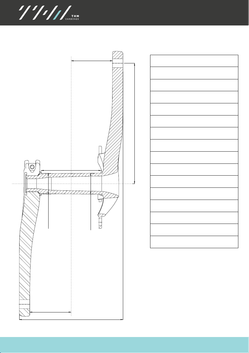
Size
Weight
293 g (0.65 lb) BCD 110 Compact
302 g (0.67 lb) BCD 130 Standard
Q-Factor
148 mm
Chainline
43,5 mm
Inner width
118 mm
Crankarm lengths
170, 172,5, 175 mm
Spindle diameter
Ø 30 mm
Boverall Bottom braket width
85,5 mm + 3 mm Spacer
Min. number of tooth:
34 teeth BCD 110 Compact
39 teeth BCD 130 Standard
Q 148 mm
B85,5 mm
Ø 30 mm
Ø 30 mm
59 mm
59 mm
170; 172,5; 175 mm mm
LOREM
T H M
C L A V I C U L A S E
11
SPECIFICATIONS
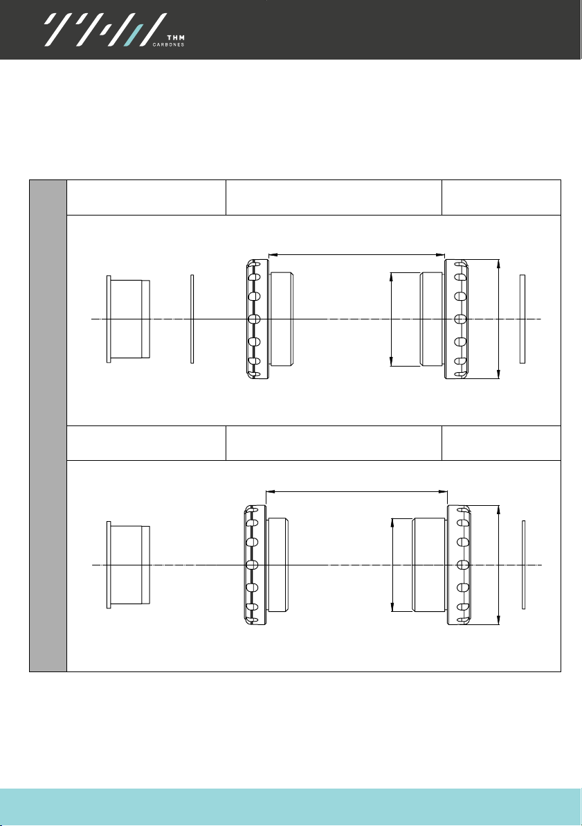
THM Bottom Bracket
All Spacer configurations are
only
valid for THM Bearings. The Spacers ensure that
the tapered cone sleeve has exactly the required position on the spindle. Therefore
we strongly recommend THM Bearings. (see also “Installing the crankset” p.23)
There are stainless steel and ceramic hybrid bearings available.
Non-drive side
(left)
BSA
Drive side
(right)
Non-drive side
(left)
ITA
Drive side
(right)
Cone
sleeve
1 mm
Spacer
2 mm
Spacer
68 ±0.2 mm
Ø 34,8 mm
Ø46 mm
Cone
sleeve
1 mm
Spacer
70 ±0,2 mm
Ø 36 mm
Ø46 mm
Threaded

LOREM
T H M
C L A V I C U L A S E
12
SPECIFICATIONS
Non-drive side
(left)
T47 85,5 mm Inboard
Drive side
(right)
Non-drive side
(left)
T47 68 mm Outboard
Drive side
(right)
Non-drive side
(left)
PF30
Drive side
(right)
2,5 mm
Cone
sleeve
1 mm
Spacer
2 mm
Spacer
85,5 ±0.2 mm
"Ø 47 mm“
Ø 50,4 mm
Cone
sleeve
1 mm
Spacer
2 mm
Spacer
68 ±0.2 mm
Ø 50 mm
Ø 46 mm
Threaded
Cone
sleeve
1 mm
Spacer
2 mm
Spacer
68 ±0.2 mm
Ø 46 mm
Ø 46 mm
Ø 49 mm
Pressfit
"Ø 47 mm“
Sealing
Sealing
Sealing
Sealing
Sealing
Sealing

LOREM
T H M
C L A V I C U L A S E
13
SPECIFICATIONS
Non-drive side
(left)
BB30
Drive side
(right)
Non-drive side
(left)
Shimano PF
Drive side
(right)
Non-drive side
(left)
386 EVO
Drive side
(right)
Cone
sleeve
1 mm
Spacer
2 mm
Spacer
68 ±0.2 mm
Ø 42 mm
Ø 46 mm
Cone
sleeve
1 mm
Spacer
2 mm
Spacer
86,5 ±0.2 mm
Ø 41 mm
Ø 44 mm
Cone
sleeve
1 mm
Spacer
2 mm
Spacer
86,5 ±0.2 mm
Ø 46 mm
Ø 49,5 mm
Pressfit
Sealing
Sealing

LOREM
T H M
C L A V I C U L A S E
14
SPECIFICATIONS
Tightening Torques
Risk of accident caused by a malfunctioning crank system due to loose screw
connections.
-
Check the required tightening torque of all screw connections after the first 100 km
-
Retighten the connections if necessary. Repeat this check every 2500km!
Nm
lbf ·in
Adjusting screw
8
89
with thread lock
Crank clamping bolt
10
89
Bearing cups
40
354
greased
Chainwheel bolts, aluminium
6
53
Pedal threads
20
177
Application area
Risk of accident caused by a malfunctioning crank system due to overload.
-
Only ever use your Clavicula component within its permitted area of application.
Clavicula SE
X1–X2
X1
Racing cycle and light cross-country terrain
X2
Touring, road
X3
medium/heavy terrain
X4
Free ride, heavy terrain
X5
Downhill,extremeterrain
WARNING
WARNING

LOREM
T H M
C L A V I C U L A S E
15
INSTALL
INSTALL
General Information
If not properly performed, assembly and maintenance work could cause
accidents resulting in serious or fatal injury.
-
Do not overestimate your technical ability. All assembly and maintenance
work should be performed by a specialist workshop for bicycles. This is the
only way to ensure the work is conducted in a professional manner.
WARNING

LOREM
T H M
C L A V I C U L A S E
16
INSTALL
Preparing the Frame
It is imperative you read and observe the safety and assembly information provided
by the manufacturer of your frame.
Secure your bicycle in an appropriate assembly stand.
If necessary remove the crankset and the old
bottom bracket.
If necessary use cleaning solvent or other similar
agents to clean the bottom bracket housing of your
frame.
Make sure that the edges of the bottom bracket
housing are plane, parallel, milled to the correct
dimension and free of burrs
–
page 11.
If necessary rework the bottom bracket housing
using an appropriate milling tool (Cyclus, ParkTool®
or other similar tool).
Make sure that the threads of the bottom
bracket housing are clean, free from paint
residues and adequately tapped into the
housing.
If necessary, rework the threads with an appropriate
cutting tool (Cyclus, ParkTool® or other similar tool).
INFO

LOREM
T H M
C L A V I C U L A S E
17
INSTALL
Bottom bracket install
To find the required bottom bracket, please m
easure the inner diameter and the width of the
bottom bracket housing of your bicycle frame.
Also check if you need threaded or pressfit bearing shells. The following table will show you
which THM bottom bracket you need:
Inner Diameter
Width
Bottom bracket
Threaded
33,8 mm
68 mm
BSA
34,8 mm
70 mm
ITA
46 mm
85,5 mm
T47 85,5 inboard
46 mm
68 mm
T47 68 outboard
Pressfit
46 mm
68 mm
PF 30
42 mm
68 mm
BB 30
41 mm
86,5 mm
Shimano PF
46 mm
86,5 mm
386 EVO
46 mm
79 mm
BBRight PF Road
Make sure that the securing bolt of the derailleur cable guide does not protrude into the
bottom bracket housing by more than 1 mm.
Apply grease to the threads and contact surfaces of the bearing cups.

LOREM
T H M
C L A V I C U L A S E
18
INSTALL
BSA / ITA
The non-drive (left) side bearing cup is marked with a groove
-
Screw the right –hand bearing
cup(R) (initially by hand) into
the drive side of the bottom
bracket housing.
-
For BSA screw
anticlockwise!
-
For ITA screw
clockwise!
-
Screw the left-hand bearing
cup(L) (initially by hand) into
the non drive side of the
bottom bracket housing.
-
For BSA and ITA screw
clockwise!
-
Use the THM Bottom bracket
tool ½ “
(1)
torque wrench to
apply 40 Nm
INFO
LOREM
T H M
C L A V I C U L A S E
19
INSTALL
T47 inboard and outboard
The non-drive side bearing cup is marked with a groove
Due to the limited length of the crank axle the T47 inboard bottom bracket works only
with 85,5 mm bottom bracket width! Ensure that your frame is not 86,5 mm!
Non-drive-side (left)
Drive-side (right)
Screw the left-hand bearing
cup(L) (initially by hand) into the
non drive side of the bottom
bracket housing.
Screw
clockwise!
Place the sealing.
Screw the right–hand bearing cup(R)
(initially by hand) into the drive side
of the bottom bracket housing.
Screw
anticlockwise!
Place the sealing.
INFO
NOTICE
T47 85,5 mm Inboard
T47 68 mm Outboard
Tool THM T47 IL
or BBT 50.4 mm
12 notch
40 Nm
Tool THM T47 IL
or BBT 50.4 mm
12 notch
40 Nm
THM Standard
Bottom bracket
Tool 40 Nm
THM Standard
Bottom bracket
Tool 40 Nm

LOREM
T H M
C L A V I C U L A S E
20
INSTALL
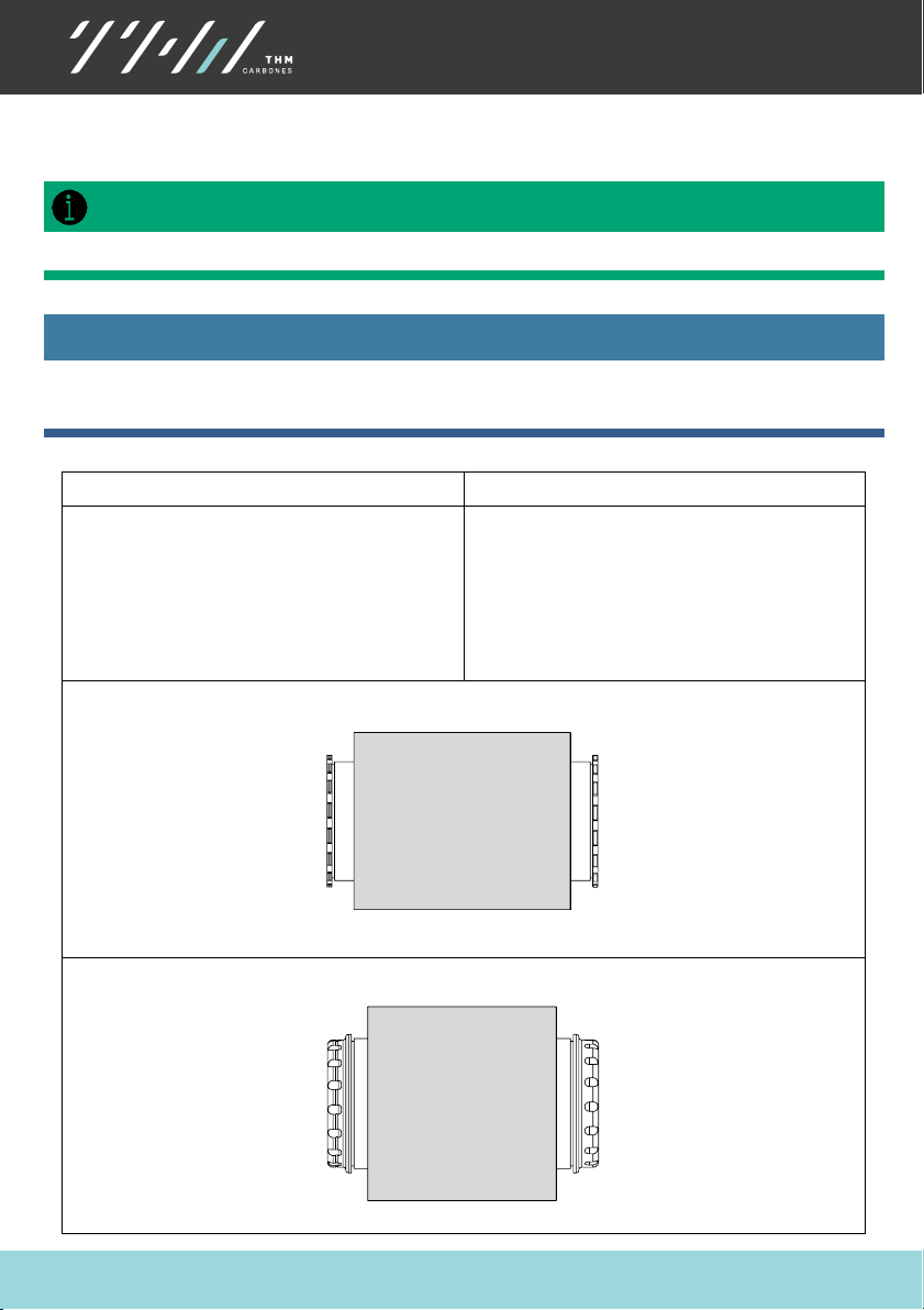
BB30 / PressFit 30 / BBrightTM PressFit
For BB30, PressFit 30 and BBright
TM
PressFit bottom brackets:
The long bearing cup with internal thread
is always located on the drive side.
The short bearing cup with external thread is always located on the non-drive side.
BB30 / PressFit 30
-
Apply grease to the threads
and all fits.
-
Insert the long bearing cup
(2)
or
(4)
by hand as far as
possible into the drive-side
of the bottom bracket
housing.
-
Screw the short bearing cup
(3)
or
(5)
by hand as far as
possible into the right-hand
bearing cup using a
clockwise
rotation.
-
Make sure that both bearing
cups are located centrally in
front of the bottom bracket
housing.
-
Use the THM Bottom
bracket tool ½ “
(1)
torque
wrench to apply 40 Nm
-
For PressFit 30 place the
sealings
BBright PressFit
TM
INFO
Table of contents
Other THM Carbones Bicycle Accessories manuals


