Sturmey-Archer HDS10 Series User manual

Instruktionen für Dynamonabe
3810.0405.026 © July 2014 by Sun Race Sturmey-Archer Inc.
543
2
1
6
1. ALLGEMEINE INFORMATIONEN
1.1 Gegenstand dieser Anleitung
Herzlichen Glückwunsch zum Erwerb einer Sturmey-Archer-Dynamonabe.
Zur bestmöglichen Funktion Ihrer Nabe folgen Sie bitte den Vorgaben dieser
Anleitung. Falls Sie mit den Produkten Probleme haben, wenden Sie sich
bitte an Ihren Sturmey-Archer-Fachhändler.
Diese Anleitung bezieht sich auf folgende Nabenmodelle :
◎Dynamonabe mit 90mm Trommelbremse: XL-FDD
◎Dynamonabe mit 70mm Trommelbremse: X-FDD
◎Dynamonabe: HDS10 Serie (HDS12)
◎Dynamonabe für Scheibenbremse: HDS20 Serie (HDS22)
1.2 Vorbereitung
1. Kontrollieren Sie die Parallelität der Ausfallenden der Vorderradgabel. Sollten
diese nicht parallel laufen, kann die Deformation der Nabenachse zu einer
Blockierung innerhalb des Nabendynamos führen, was sich durch Geräusche
bemerkbar macht.
2. Montieren Sie den Nabendynamo in der Vorderradgabel, sodass sich die Seite
mit der Anschlussklemme auf der rechten Seite des Fahrrades befindet. Nur so
ist die einwandfreie Funktion des Dynamos gewährleistet.
3. Prüfen Sie, ob die Anschlussklemme sicher verbunden ist, bevor Sie die
Dynamonabe verwenden.
4. Die 2,4 W Version ist für den Betrieb der Frontleuchte geeignet. Bei
Anschluss einer Front- und Rückleuchte, ist die 3,0 W Version erforderlich.
5. Die Getriebeeinheit der Nabe darf nicht auseinander genommen werden.
2. EINBAU
2.1 XL-FDD, X-FDD
1. Bauen Sie die Nabe in das Laufrad ein.
2. Wählen Sie eine passende Bremsarmbandage und fixieren Sie hiermit den
Bremsarm lose an der Vorderradgabel.
3. Richten Sie das Laufrad mittig aus, montieren Sie die gezahnte
Sicherungscheibe (2), (ggf. Schutzblechstrebe (3) und Korbstrebe (4)) sowie
die Hutmutter (5) auf derAchse und ziehen Sie die Mutter auf 22-23Nm an.
4. Ziehen Sie die Mutter der Bremsarmbandage in dieser Position auf 2 Nm an.
△! Sollte das mit der Erdungsklemme verbundene Kabel nicht richtig
geerdet sein, überprüfen Sie, ob die Zähne der Sicherungsscheibe (2) die
Lackierung der Vorderradgabel durchdringen. Tun Sie dies nicht, so
beeinträchtigt dies die Leistung der Lampe. Entfernen Sie in diesem Fall
ein wenig Lackierung an der entsprechenden Stelle.
Für einen gleichmäßigen Stromfluss ist derAnschluss beider Kabel
erforderlich.
2.2 HDS10, HDS20
Siehe 2.1, Schritt 2.1.2 und 2.1.4 überspringen.
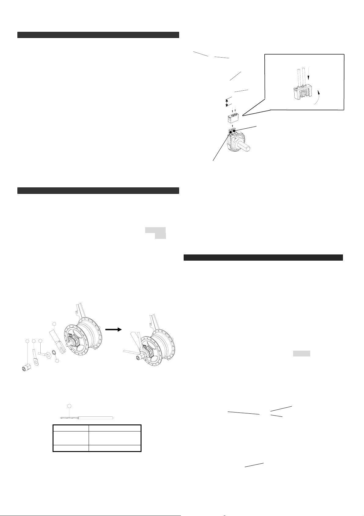
2.3 Anschluss der Kabel
1. Verdrehen Sie die Kabeldräte (6) bevor Sie sie anschließen.
2. Schließen Sie die Kabel so an, wie in der nachfolgenden Abbildung gezeigt.
3. Empfohlene Kabel:
4. Vertauschen Sie nicht versehentlich Rahmenkabel (7) und Beleuchtungskabel
(8). Die Beleuchtung funktioniert nur bei korrektemAnschluss.
5. Entfernen Sie beim Anschließen der Kabel den Lack von den
Anschlussklemmen (9)/(10) der Lampe.
6. Schließen Sie die Kabel so an, wie in der nachfolgenden Abbildung gezeigt.
Typ Litzenkabel
Draht Größe (AWG) 22
Ø ~ 0,8
Isolierung Ø 1,8 - 2,0mm
k
l !!! : Biegen Sie die Drähte und führen
Sie sie entlang der Rillen.
j
Einführen
i
Biegung
~ 15mm
Rahmenanschlussklemme
Lampenanschlussklemme
2.4 Überprüfen der Beleuchtung
1.Drehen Sie das Vorderrad und überprüfen Sie die Beleuchtung
△!Fahren Sie das Fahrrad niemals ohne geschlossene Anschlussabdeckung,
da sonst die Gefahr besteht, dass das Kabel in das Laufrad gelangt.
3. BREMSE
3.1 Züge mit geschlossenem Ende
1. Verbinden Sie den Zug mit dem Bremshebel am Lenker.
2. Montieren Sie den Zapfen der Stellschraube in den Schlitz des Bremsarms.
3. Hängen Sie den Sicherungsbolzen in den Bremshebel der Nabe ein.
3.2 Klemmschraube
1. Verbinden Sie den Zug mit dem Bremshebel am Lenker.
2. Montieren Sie den Zapfen der Stellschraube in den Schlitz des Bremsarms.
Ziehen Sie den Innenzug durch das Loch der Klemmschraubenmutter und
positionieren diese im Bremshebel der Nabe. Spannen Sie den Zug durch
weiteres Ziehen des Innenzuges durch die Klemmschraube.
3. Regulieren Sie die Einstellschraube(11), sodass ca. 5mm des Gewindes über
der Sicherungsmutter(12) zu sehen sind.
4. Halten Sie den Bremshebel auf der “Brems”-Position, sodass der Innenzug
gespannt ist. Halten Sie die “Mutter” der Klemmschraube an der Innenseite
des Bremsarms mit einem Schraubenschlüssel und ziehen Sie den
Schraubenteil an der Außenseite des Bremsarms fest (2-3Nm).
3.3 Bremseinstellung
1. Lockern Sie die Sicherungsmutter (12).
2. Drehen Sie die Einstellschraube (11) bis die Bremse anzieht.
3. Lockern Sie die Einstellschraube (11) bis das Rad gerade eben frei läuft
4. Ziehen Sie die Sicherungsmutter (12) fest.
△!Um die maximale Bremswirkung zu gewährleisten, vermeiden Sie starke
Biegungen und Knicke im Bremszug.
(11)
Bremsarm (12)
Bremshebel
3.4 Scheibenbremse für HDS20
Bitte folgen Sie der Anleitung des Bremsenherstellers.
Instructions for Dynohub
3810.0405.026 © July 2014 by Sun Race Sturmey-Archer Inc.
1. GENERAL INFORMATION
1.1 Scope of this leaflet
Congratulations on your purchase of a Sturmey-Archer dynohub. For the best
performance, please follow instructions in this leaflet. Please contact your
dealer if any problems are experienced with these products.
This leaflet refers to the following hub types :
Dynohub with 90mm drum brake◎: XL-FDD
Dynohub with 70mm drum brake◎: X-FDD
Dynohub: HDS10◎series (HDS12)
Dynohub for disc brake: HDS20◎series (HDS22)
1.2 Preparation
1. Check the degree of parallel of the front fork end. If the front end is severely
out of parallel, deformation of the hub axle may cause noise from an
obstruction inside the dynohub to be generated.
2. Install the dynohub to the front fork so that the side with the connection
terminal is on the right when facing toward the front of the bicycle. If the side
with the connection terminal is facing toward the left, the dynohub may not
turn properly while riding.
3. Check that the dynohub connection terminal is securely connected before
using the dynohub.
4. Use a 6V/2.4W bulb for the front light and a 6V/3.0W bulb for the front light
and taillight.
5. Do not disassemble the internal hub mechanism.
6. The dynohub will cause the turning of the wheel to become slightly heavier
because of the magnet inside the hub.
2. INSTALLATION
2.1 XL-FDD, X-FDD
1. Set the wheel-set done.
2. Select a suitable brake arm clip to clamp the brake arm loosely to the front
fork.
3. Fit hub into the front fork (1) with the wheel centralized. Fit toothed axle
washer (2), Mudguard stay (3), Basket stay (4), Dome-Nut (5), tighten the
dome nuts to a torque of 22-23Nm.
4. Tighten the brake arm clip firmly in this position to either 2 Nm torque.
△!If the cable connected to the ground terminal is not properly grounded,
check that the Toothed axle washer (2) perforates the paint surface of the
front fork. If the Toothed axle washer (2) is not perforating the paint
surface, the light will not illuminate properly, so scrape away a small
amount of paint from the front fork.
It is recommended that you connect the two wires to ensure that current
flows smoothly.
3
4
5
2
1
2.2 HDS10, HDS20
See section 2.1. Skip steps 2.1.2 and 2.1.4.
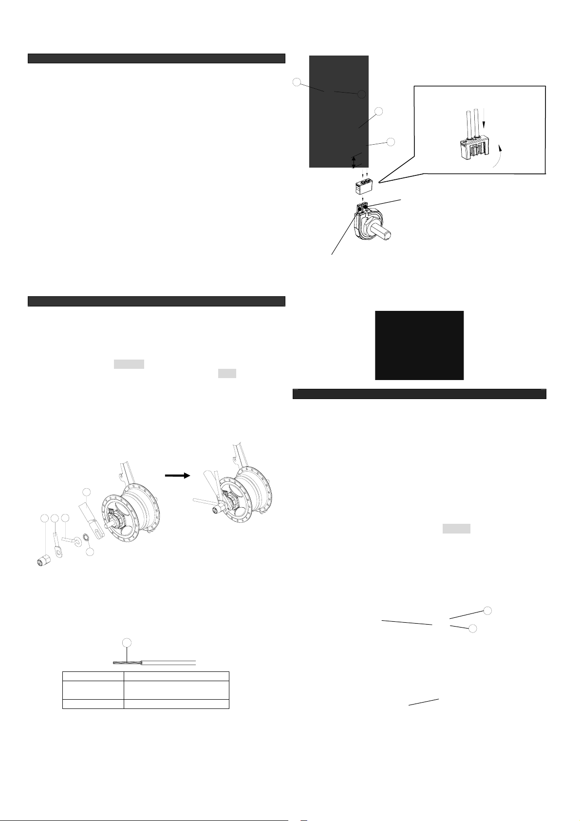
2.3 Connection of the cable
1. Twist the cable wires (6) before connecting them so that they stay together.
2. Connect the cable as shown in the illustration below.
3. Recommended wire specification
6
Type Stranded
Wire Size (AWG) 22
Diameter approx. 0.8
Insulation Diameter 1.8 - 2.0mm
4. Do not switch over the frame cable (7) and the light cable (8) by mistake. If
the cables are connected incorrectly, the light will not illuminate.
5. Scrape away the paint from the light’s frame connection terminal (9) and the
light connection terminal (10) when connecting the cables.
6. Connect the cables as shown in the illustration below.
7
8
9
Note :
Bend the cable wires and run
them along the grooves.
Insert
Bend
Approx.15mm
Frame connection terminal
Light connection terminal
10
2.4 Checking the light illumination
1.Rotate the front wheel and check the light illumination.
△! Do not ride the bicycle while the connector cover is removed, otherwise
the cable might get caught in the bicycle wheel.
3. BRAKE
3.1 Closed End Cables
1. Attach the cable to the handlebar brake lever.
2. Locate the brake adjusting spigot in the slot of the brake arm.
3. Fit the cable nipple into the hub brake lever assembly.
3.2 Pinch Bolt
1. Attach the cable to the handlebar brake lever.
2. Locate brake adjusting spigot into slot on the brake arm. Push the cable inner
wire through the hole in the pinch bolt nut and locate this into the cradle into
the brake lever. Pull the inner wire through the pinch bolt until taut.
3. Set adjuster (11) so that there is approximately 5mm of thread showing above
the locknut (12).
4. Holding the brake lever in the ‘brake on’ position with the inner cable taut,
hold the pinch bolt ‘nut’on the inside of the brake arm with a spanner and
tighten pinch bolt ‘screw’on the outside arm (2-3Nm).
3.3 Brake Adjustment
1. Slacken the brake adjuster locknut (12).
2. Turn the adjuster (11) until the brake is applied.
3. Slacken the adjuster until the wheel can just be turned freely.
4. Tighten the locknut (12).
△! To maintain maximum braking efficiency avoid sharp bends and kinks
in the cable.
Brake arm
Hub brake lever
11
12
3.4 Disc brake for HDS20
Please check and adjust according to brake manufacturers manual.
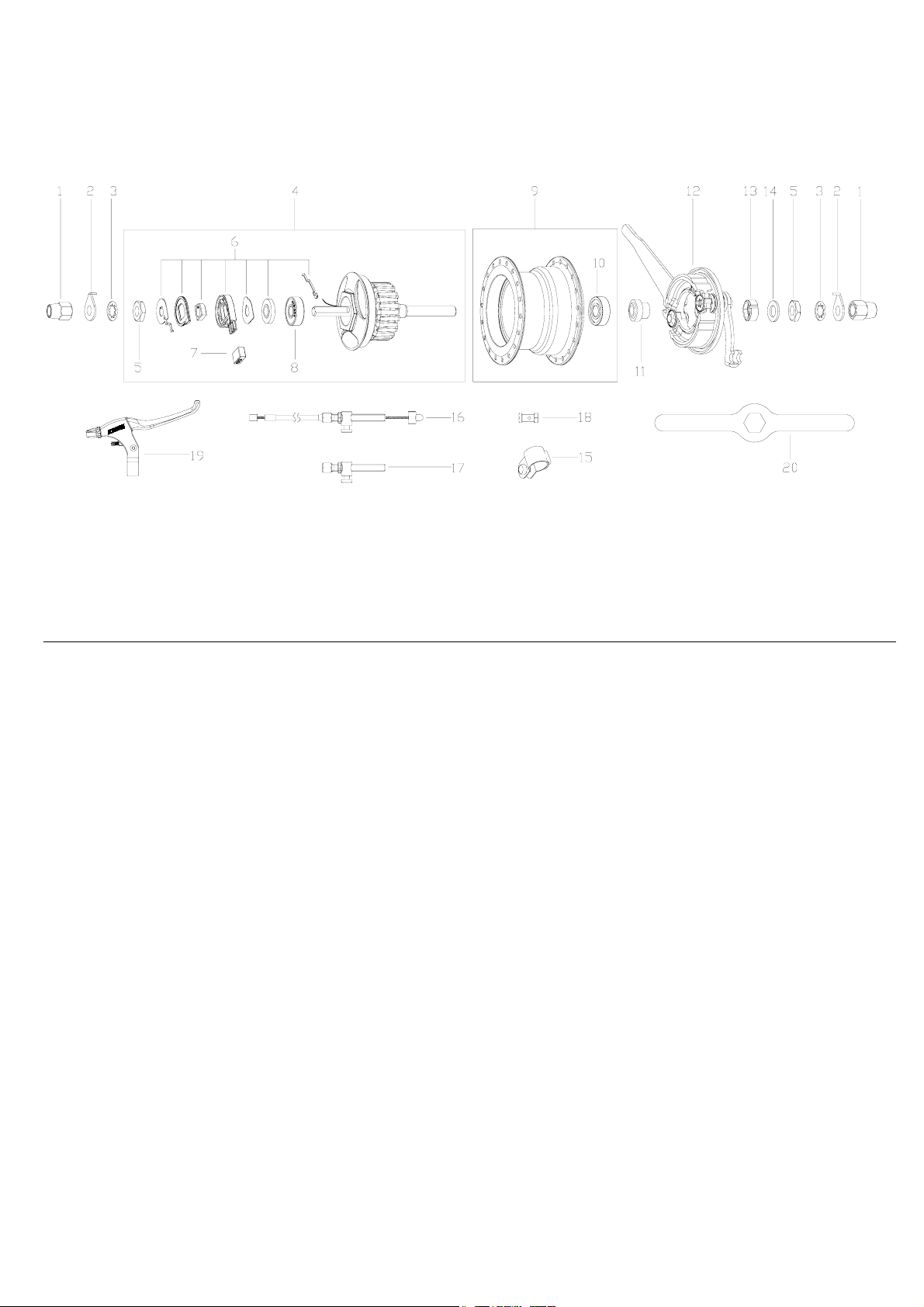
Part List – X-FDD Dynohubs
Item Sales Item Sales Item Sales
No. No. Description No. No. Description No. No. Description
1 HMN 386 Dome Nut M9 9 HSB 521 2.4W X-FDD Hub ShellAssy. 15 HSJ 702 Brake Arm Clip 17.5mm
2 HMW 528 Safety Washer w/Magnet and Bearing HSJ 703 Brake Arm Clip 22.2mm
3 HMW 527 Toothed Lock washer 3/8" HSB 522 3.0W X-FDD Hub Shell Assy. 16 HSK 730 Brake Cable Complete 900mm
4 HSX 146 2.4W Dynohub Internal w/Magnet and Bearing 17 HSB 422 Brake Adjuster Assy.
HSX 147 3.0W Dynohub Internal 10 HSS 035 Bearing 6000UU 18 HSK 715 Pinch Bolt
5 HMN 377 Locknut M9, t=4.7, hex 17 11 HSA 373 Brake Plate Bush 19 HSK 742 Brake Lever BLS80 RH
6 HSE 001 Connector Assy. 12 HSB 430 70mmAlloy Front Brake PlateAssy. HSK 743 Brake Lever BLS80 LH
7 HSE 002 Plug for Connector 13 HSA 372 Brake Plate Spacer 20 HTR 139 Spanner for Side Cap
8 HSS 036 Bearing 629UU 14 HMW 146 Washer 1/16”
This manual suits for next models
5
Table of contents
Languages:
Other Sturmey-Archer Bicycle Accessories manuals


Popular Bicycle Accessories manuals by other brands

Kettler
Kettler Flexbox 600 Assembly and operating instructions

motogadget
motogadget motoscope mini Operating and installation guide

WeeRide
WeeRide CoPilot Instructions for assembly and operation

Burley
Burley PICCOLO Owner's instruction and safety manual

Cateye
Cateye Rapid micro TL-LD620-R manual

FUXON
FUXON Starlight II instruction manual


