THM Clavicula M3 User manual

Clavicula M³
Road
MTB
Instruction book
THM Clavicula M³_3_en, 2013-02

Don't forget that your THM component is a lightweight carbon design.
Be aware of this when carrying out assemly and maintenance work and when
handling the component. Proceed with utmost care!


4
Clavicula M³
Contents
INTRODUCTION
Preface . . . . . . . . . . . . . . . . . . . . . . . . . . . . . . . . 5
SAFETY
Intended use . . . . . . . . . . . . . . . . . . . . . . . . . . . . 6
Fundamental safety precautions . . . . . . . . . . . . . 6
Assembly & maintenance . . . . . . . . . . . . . . . . . . 6
On the road . . . . . . . . . . . . . . . . . . . . . . . . . . . . 7
Transport & storage . . . . . . . . . . . . . . . . . . . . . . 7
SPECIFICATIONS
Scope of delivery . . . . . . . . . . . . . . . . . . . . . . . . 8
Bottom bracket . . . . . . . . . . . . . . . . . . . . . . . . . . 9
Size . . . . . . . . . . . . . . . . . . . . . . . . . . . . . . . . . . . 10
Tightening torques . . . . . . . . . . . . . . . . . . . . . . . 11
Application area . . . . . . . . . . . . . . . . . . . . . . . . . 11
ASSEMBLY
Installing the Clavicula . . . . . . . . . . . . . . . . . . . . 12
Preparing the frame . . . . . . . . . . . . . . . . . . . . . . 12
Spacers . . . . . . . . . . . . . . . . . . . . . . . . . . . . . . . 13
Installing the bottom bracket . . . . . . . . . . . . . . . 14
BSA/ITA . . . . . . . . . . . . . . . . . . . . . . . . . . . . . . 14
BB30/PressFit 30/BBright™ PressFit . . . . . . . . . 15
Press-fit/EVO386 . . . . . . . . . . . . . . . . . . . . . . . 16
BBright™ Direct Fit . . . . . . . . . . . . . . . . . . . . . 16
Installing the spider . . . . . . . . . . . . . . . . . . . . . . 16
Assembling the chainwheels . . . . . . . . . . . . . . . 18
Installing the cranks . . . . . . . . . . . . . . . . . . . . . . 18
Adjusting the bottom bracket . . . . . . . . . . . . . . . 20
Assembling the pedals . . . . . . . . . . . . . . . . . . . . 21
Finishing touches . . . . . . . . . . . . . . . . . . . . . . . . 21
MAINTENANCE
Important maintenance information . . . . . . . . . . 22
Disposal . . . . . . . . . . . . . . . . . . . . . . . . . . . . . . . 23
Before each trip . . . . . . . . . . . . . . . . . . . . . . . . . 24
Checking the bottom bracket clearance . . . . . . . 24
Regular maintenance . . . . . . . . . . . . . . . . . . . . . 25
Dismantling the bottom bracket . . . . . . . . . . . . . 26
LEGAL
Liability for defects . . . . . . . . . . . . . . . . . . . . . . . 28
Fair deal promise . . . . . . . . . . . . . . . . . . . . . . . . 28
Crash Replacement . . . . . . . . . . . . . . . . . . . . . . . 28

5
Clavicula M³
Introduction
Preface
This manual is an integral part of your THM component and it provides you with infor-
mation regarding the safe operation of your THM-Clavicula crank system.
Read this manual carefully prior to assembling your THM component. Always read and
observe all of the assembly and maintenance instructions in this manual, as well as those
provided in the manuals of other manufacturers whose products are used on your bicycle
(e.g. frame, chainwheels, pedals, etc.).
WARNING
Non-observance of the information contained in this manual could result in an accident
and death or serious injury.
You will encounter the following symbols and references in this manual:
The index finger instructs you to perform a particu-
lar action.
The arrow indicates the consequence of your
action.
WARNING
This safety message indicates a hazardous situation
which, if not avoided, could result in death or serious
injury.
CAUTION
This safety message indicates a hazardous situation
which, if not avoided, could result in minor or moder-
ate injury.
NOTICE
This message warns of a risk of material damage.
This refers to additional information or tips.
Retain this manual for other users of your THM components.
Make sure that all users read, understand and observe this manual.
If you ever sell or give away your THM components, this manual should be transferred
to the new owner.
We hope you get a lot of joy from your THM components!
Your THM-Carbones Team

6
Clavicula M³
Safety
Intended use
WARNING
Any use other than that intended can cause accidents resulting in death or serious injury.
THM-Clavicula crank systems have been exclusively designed
- for installation on standard racing cycles, time trial and mountain bikes.
- for the permitted area of application – see Application area, page 11.
Fundamental safety precautions
The following warnings for the THM-Clavicula component apply to all Clavicula models
(Clavicula Road, Clavicula MTB etc.), unless otherwise specified.
For the time being we limit the service life of your THM-Clavicula crank system to
100,000 km or 10 years. It is imperative you contact us before continuing to use your
THM-Clavicula crank system after one of these limits has expired!
Always remember that riding a bicycle involves potential danger for the rider and other
road users, as well as for the bicycle and its components. Even if protective equipment
and safety devices are used, accidents resulting in death or serious injury can still occur.
You should also rely on your common sense and avoid any unreasonable behaviour!
Assembly & maintenance
WARNING
Risk of accident caused by assembly and maintenance work which has not been con-
ducted in a professional manner.
-Do not overestimate your technical ability. All assembly and maintenance work should
be performed by a specialist workshop for bicycles. This is the only way to ensure that
work is conducted in a professional manner.
-Always observe all of the specified tightening torques for the screw connections.
-Only use suitable, undamaged, high-quality tools.
-Only ever use original THM components which are available from your specialist dealer
or directly from THM.
-Never make any modifications to your THM components.
-Check your crank system (incl. cranks, bottom bracket, chainwheels) to make sure it is
undamaged and functioning properly before every ride. Send us your THM-Clavicula
component before further use if damage is visible (cracks, fractures, deformations, etc.)
or if you are in any doubt about its functionality.
-Check your THM components before each journey to ensure the surfaces are completely
undamaged. Send us your THM components for inspection before further use if damage
is visible (deep scratches in the paintwork which extend into the carbon structure, large
abrasions, etc.), if you are in any doubt about their functionality or if the Clavicula let-
tering is abraded at one or more points (wear indicator).
-Always ensure your bicycle is maintained in a flawless condition. Care and maintenance
will prolong the service life of your bicycle and its components and also improve your
personal safety.

7
Clavicula M³
Safety
On the road
WARNING
Danger of accidents due to improper behaviour or improper equipment during riding.
-Always ride with foresight, attention and a readiness to brake.
-Adjust your speed to the prevailing conditions (traffic, weather, visibility, etc.).
-Do not use your THM components at ambient temperatures below -10°C (14°F).
-Do not exceed the maximum overall weight for which your THM components have
been approved – see Size, page 10.
-Do not perform jumps with your bicycle as this generates an enormous amount of force.
-Always comply with the traffic regulations that are in force in the country where you are
using your bicycle.
-When riding your bicycle you should always wear a high quality cycling helmet (e.g.
ANSI certified) that is in excellent condition. Your clothing should be close-fitting but
not restrictive.
-Only ride your bicycle if you are in good physical condition and your bicycle and all of
its components are in perfect working order.
-If you are involved in a heavy fall you should not continue riding your bicycle. If such
a case occurs, send us your THM components for inspection, even if no external damage
is visible! In your own interest you should treat all components on your bicycle which
are produced by other manufacturers in the same way.
When riding your mountain bike, also comply with the directives of the International
Mountain Bike Association (IMBA):
-Only use permitted routes.
-Avoid leaving tracks.
-Always keep your bicycle under control.
-Ride in a manner that is suitable for the terrain.
-Do not startle any animals.
-Always ride in an anticipatory manner.
-Be prepared for any eventuality.
For more information please visit www.imba.com .
Transport & storage
WARNING
Risk of accident caused by damaged bicycle components.
-Always transport your bicycle in an appropriate and careful manner.
-Do not store your THM components at an ambient temperature below -15°C (5°F) or
above 55°C (131°F).
Risk of accident.
-Do not allow children to play with your bicycle.

8
Clavicula M³
Specifications
Scope of delivery
(1) Adjusting screw
(2) Crank, left
(3) Spacer ring, 1× 2.5mm (Road)
(4) Spacer ring, 1× 9.7mm (MTB)
(9) Lockring for spider (MTB)
(10)Hollow screw for spider (Road),
5× M8×0.75 × 10mm
(11)Spider* (optional)
(12)Axle crank
Instruction book
Not included in delivery:
(5) Bottom bracket (optional)
–seeBottom bracket, page 9
(6) Bearing cup, left (marked by groove)
(7) Spacer, 2.5mm
(8) Bearing cup, right
(13)THM adjusting tool
(14)THM bottom bracket tool (optional)
(15)THM lockring tool (MTB)
These items must be ordered separately if necessary.
*without chainwheels and chainwheel bolts
23
6
5
8
12110 11
4
7
9
13
14 15
9
Clavicula M³
Specifications
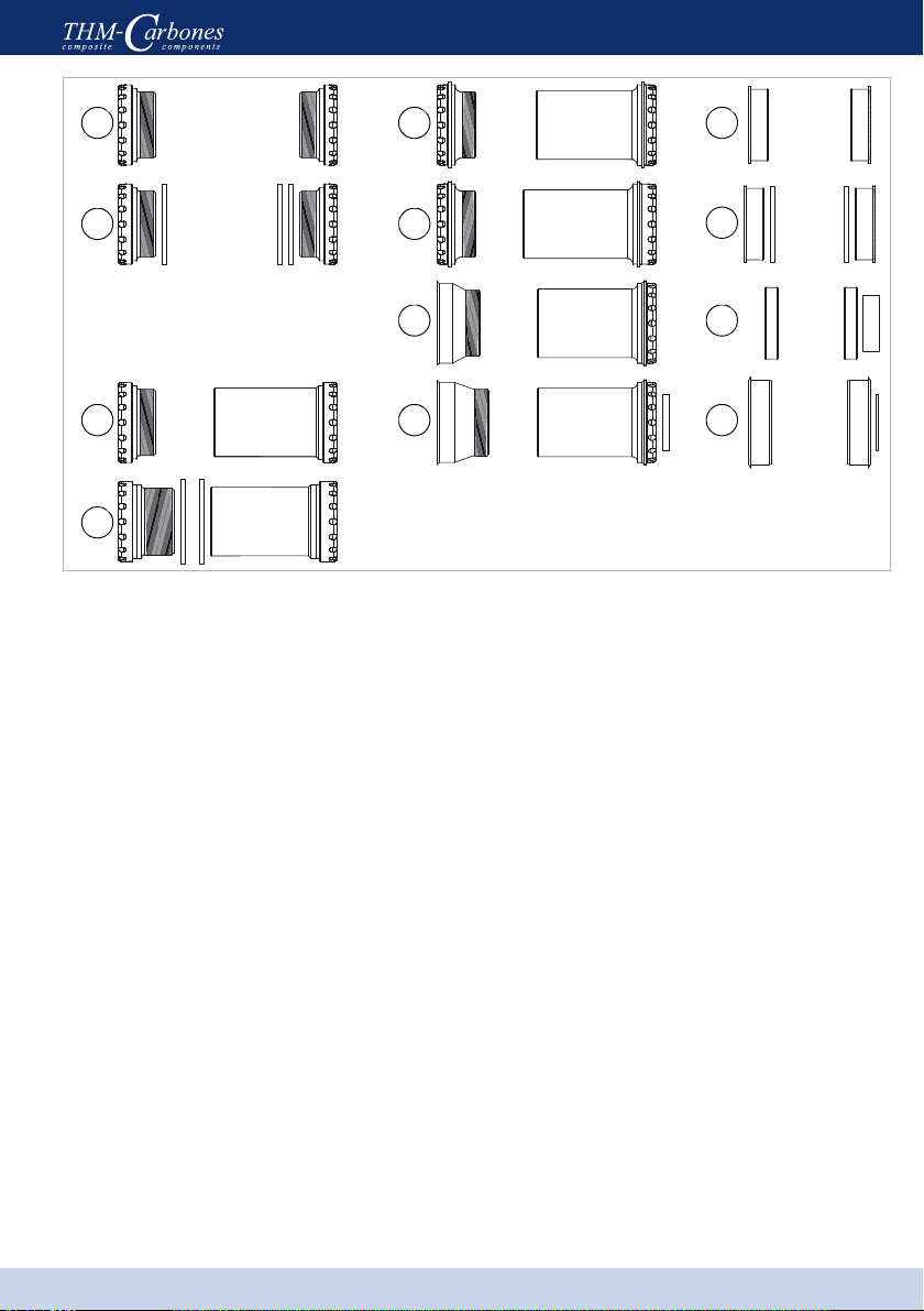
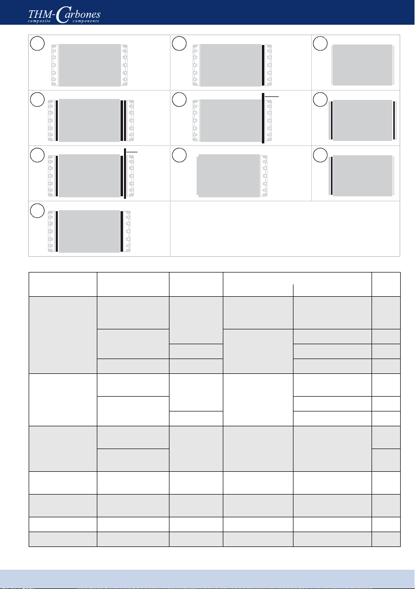
Bottom bracket
(a) Road (BSA/ITA): Bearing cup left/right
(b) MTB (BSA): Bearing cup left/right,
3× spacer ring (2.5mm)
(c) BB30 Road: Bearing cup left/right
(d) BB30 MTB: Bearing cup left/right,
2× spacer ring (2.5mm)
(e) PressFit 30 Road: Bearing cup left/right
(f) PressFit 30 MTB: Bearing cup left/right
(g) BBright™ PressFit Road:Bearing cup left/right
(h) BBright™ PressFit MTB:Bearing cup left/right,
1× spacer ring, right (4.0mm)
(i) Press-fit Road: Bearing cup left/right
(k) Press-fit MTB: Bearing cup left/right,
2× spacers (2.0mm)
(l) BBright™ Direct Fit Road: 2× bearings,
1× spacer ring, right (9.0mm)
(m) EVO386 Road (FSA®): Bearing cup left/right,
1× spacer ring, right (1.0mm)
a
g
i
l
e
b
d
fk
m
c h
10
Clavicula M³
Specifications
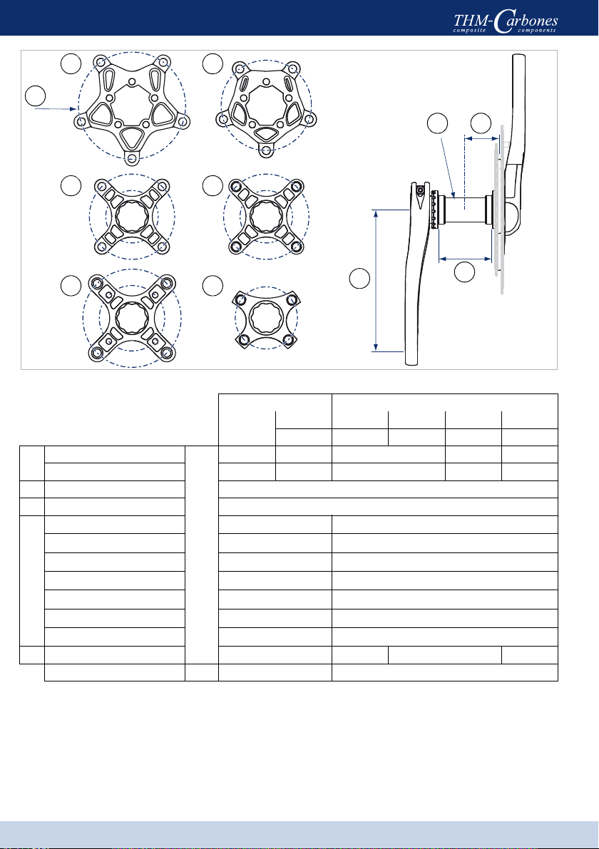
Size
*Technical specifications, dimensions and weights are to be understood with the corresponding tolerances
and can differ slightly from your THM components.
** BSA (1.37"×24 tpi) / ITA (36×24 tpi)
*** Total weight = rider + bicycle + luggage
A
D
B
EC
12
3
56
4
A
CE
BD
Road MTB
Compact 3–104/64 2–104/64 2–120/80 XX1–76
*(1)(2)(3)(4)(5)(6)
(A) Ø bolt circle
mm
130 110 104/64 120/80 76
Teeth, min. 39 34 32/21 37/25 26
(B) Crank length 170.0/172.5/175.0
(C) Ø axle 30
(D)
BSA (ITA)** 68.0 (70.0) ±0.5 68.0/73.0 ±0.5
BB30 68.0±0.5 (Ø 42.0) 68.0/73.0±0.5 (Ø 42.0)
PressFit 30 (SRAM®)68.0±0.5 (Ø 46.0) 73.0±0.5 (Ø 46.0)
BBright™ PressFit 79.0±0.5 (Ø 46.0) 84.0±0.5 (Ø 46.0)
Press-fit (Shimano®)86.5±0.5 (Ø 41.0) 89.5/92.0±0.5 (Ø 41.0)
BBright™ Direct Fit 79.0±0.2 (Ø 42.0) –
EVO386 (FSA®)86.5±0.5 (Ø 46.0) –
(E) Chain line (ITA) 43.5 (44.5) 50.0 49.5 47.0
Total weight, max.*** kg(lb) 110 (243) 120 (265)
11
Clavicula M³
Specifications
Tightening torques
WARNING
Risk of accident caused by a malfunctioning crank system due to loose screw connections.
-Check the required tightening torque of all screw connections after the first 100 km - re-
tighten the connections if necessary. Repeat this check every 2500km!
Application area
WARNING
Risk of accident caused by a malfunctioning crank system due to overload.
-Only ever use your Clavicula component within its permitted area of application.
X1 Racing cycle and light cross-country terrain
X2 Touring, road
X3 medium/heavy terrain
X4 Free ride, heavy terrain
X5 Downhill, extreme terrain
N·m(lbf·in) max.
Bearing cups 40 (354) greased
Adjusting screw 6 (53) dry
Crank clamping bolt 8 (71)
with thread lockHollow screw for spider 6 (53)
Lockring spider 30 (266)
Chainwheel bolts, aluminium 6 (53)
greasedChainwheel bolts, steel 12 (106)
Pedal threads 20 (177)
Clavicula M³ Road X1–X2
Clavicula M³ MTB X1–X3
12
Clavicula M³
Assembly
Installing the Clavicula
WARNING
If not properly performed, assembly and maintenance work can cause accidents resulting
in serious or fatal injury.
-Do not overestimate your technical ability. All assembly and maintenance work should
be performed by a specialist workshop for bicycles. This is the only way to ensure that
work is conducted in a professional manner.
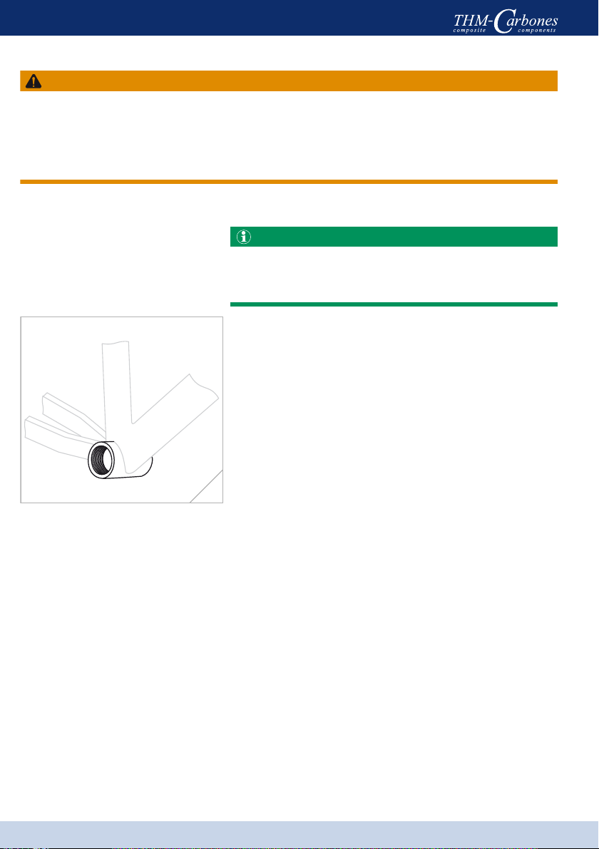
Preparing the frame
It is imperative you read and observe the safety and
assembly information provided by the manufacturer
of your frame.
Secure your bicycle in an appropriate assembly
stand.
If necessary remove the crankset and the old bottom
bracket.
If necessary, use cleaning solvent or other similar
agents to clean the bottom bracket housing of your
frame.
Make sure that the edges of the bottom bracket
housing are plane, parallel, milled to the correct
dimensions and free of burrs – see Size, page 10.
If necessary, rework the bottom bracket housing
using an appropriate milling tool (Cyclus, ParkTool
or other similar tool).
Make sure that the threads of the bottom bracket
housing are clean, free from paint residues and
adequately tapped into the housing. If necessary,
rework the threads with an appropriate cutting tool
(Cyclus, ParkTool or other similar tool).
(fig. 1)
1
13
Clavicula M³
Assembly
Spacers
E-TYPE,
Chain-
guide, …
E-TYPE,
Chain-
guide, …
A
B
C
D
E
F
G
H
I
K
Bottom bracket
housing Bottom bracket Front derail-
leur type
Spacers Fig.
Anticlockwise Clockwise
68.0mm (70.0mm)
Road BSA (ITA);
BB30 Road; PressFit
30 Road Clip-on/
braze-on
0 0 (A)
MTB BSA 1× 2.5mm
2× 2.5mm (B)
E-TYPE 1× 2.5mm + E-TYPE (C)
BB30 MTB Clamp 1× 2.5mm (D)
73.0 mm
BB30 MTB; PressFit
30 MTB Clamp 0
0(A)
MTB BSA 1× 2.5mm (E)
E-TYPE 0 + E-TYPE (F)
79.0 mm
BBright™ PressFit
Road Clip-on/
braze-on 0 0
(G)
BBright™ Direct Fit
Road –
84.0 mm BBright™ PressFit
MTB Clamp 00
(G)
86.5 mm Press-fit
Road;Evo386 Road
Clip-on/
braze-on 0 0 (H)
89.5 mm Press-fit MTB sym. Clamp 1× 2.0mm 1× 2.0mm (I)
92.0 mm Press-fit MTB asym. Clamp 1× 2.0mm 0(K)

14
Clavicula M³
Assembly
Installing the bottom bracket
Do not use the Clavicula Road in combination with an E-TYPE front derailleur!
The THM socket wrench(1)(fig. 3), which can be used as a torque wrench, can be ob-
tained from us or from your specialised dealer.
Measure the width of the bottom bracket housing of
your bicycle frame.
Identify the type of front derailleur used on your
bicycle.
Use the table to determine the correct number of
spacers for both sides of the bottom bracket –
see Spacers, page 13.
Make sure that the securing bolt of the derailleur
cable guide does not protrude into the bottom
bracket housing by more than 1mm.
Apply grease to the threads and contact surfaces of
the bearing cups.
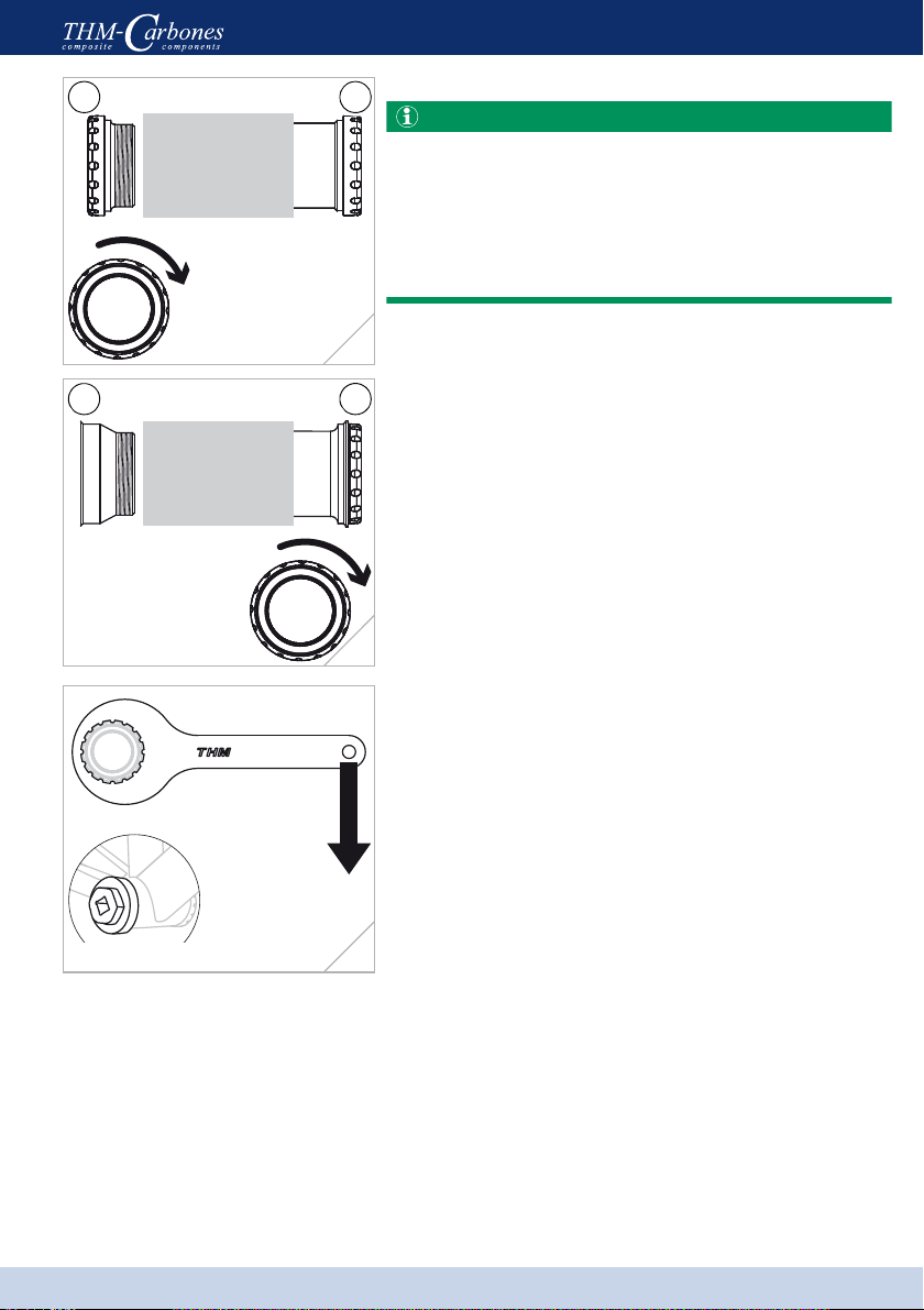
BSA/ITA
Fit the correct number of spacers to the right-hand
bearing cup (R).
Screw the right-hand bearing cup (R) – initially by
hand – into the right-hand side of the bottom bracket
housing using an anti-clockwise (BSA) or clockwise
(ITA) motion.
Fit the correct number of spacers to the left-hand
bearing cup (L) (marked by groove).
Screw the left-hand bearing cup (L) – initially by
hand – into the left-hand side of the bottom bracket
housing using a clockwise motion (BSA & ITA).
(fig. 2)
Tighten both bearing cups using a tightening torque
of 40N·m (354lbf·in).
This torque corresponds to a manual force of
approx. 20kg (44lb) at the end of the THM bottom
bracket tool. (fig. 3)
L R
2
20 kg
(44 lb)
40 N·m (354 lbf·in)
1
3
15
Clavicula M³
Assembly
BB30/PressFit 30/BBright™ PressFit
When dealing with BB30, PressFit 30 and BBright™
PressFit bottom brackets, the bearing cup with internal
thread (2) or (4) is always located to the right, while
the bearing cup with external thread (3) or (5) is
always located to the left.
–seeBottom bracket, page 9.
Fit the correct number of spacers to the bearing
cup (2).
Insert the bearing cup (2) or (4) by hand as far as
possible into the right-hand side of the bottom
bracket housing.
Fit the correct number of spacers to the bearing
cup (3).
Screw the bearing cup (3) or (5) by hand as far as
possible into the right-hand bearing cup using a
clockwise rotation.
Make sure that both bearing cups are located cen-
trally in front of the bottom bracket housing.
(fig. 4, 5)
Tighten the bearing cup (3) or (4) using a tightening
torque of 40N·m (354lbf·in).
This torque corresponds to a manual force of
approx. 20kg (44lb) at the end of the THM bottom
bracket tool.
(fig. 6)
3 2
4
5 4
5
20 kg
(44 lb)
40 N·m (354 lbf·in)
6
16
Clavicula M³
Assembly
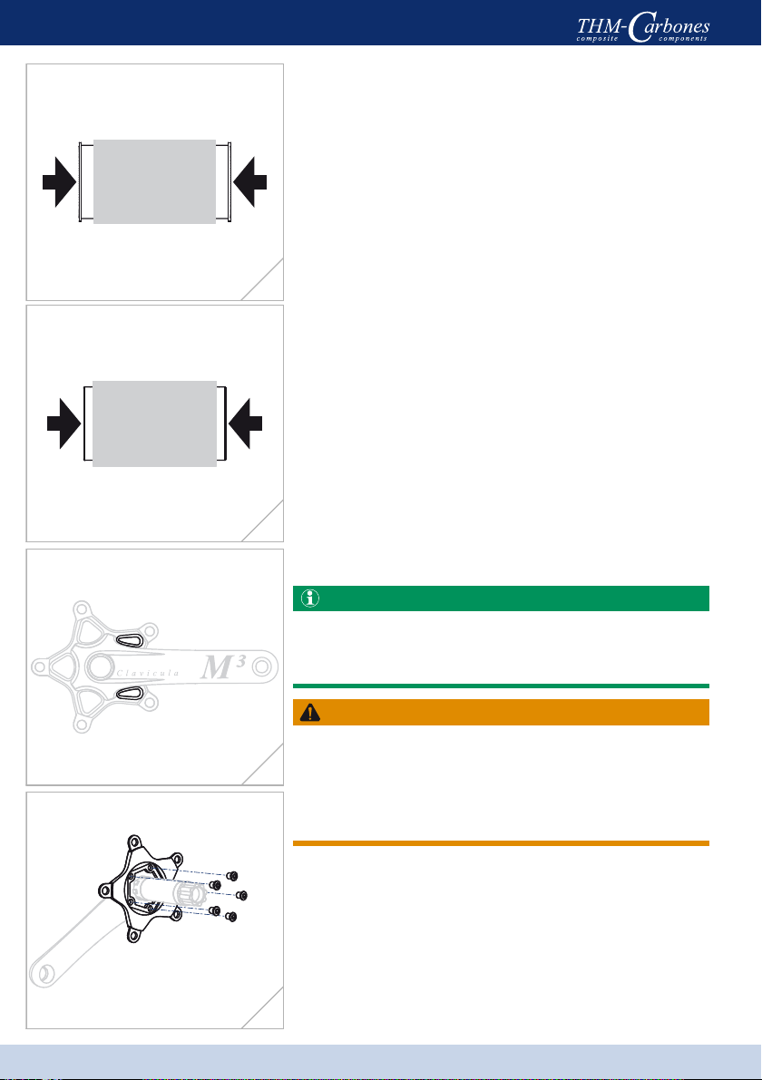
Press-fit/EVO386
Fit the correct number of spacers to the bearing
cups – see Spacers, page 13.
Press both bearing cups simultaneously into the
bottom bracket housing as far as possible by using a
suitable pressing tool (e.g. Park Tool®).
(fig. 7)
BBright™ Direct Fit
Press both bearings simultaneously into the bottom
bracket housing as far as the housing stop by using
a suitable pressing tool (e.g. Park Tool®).
(fig. 8)
Installing the spider
Road
The spider is positioned correctly when the two small
contoured sections on the outer side are located next
to the arm of the axle crank. (fig. 9)
WARNING
Risk of accident caused by a malfunctioning spider
due to the use of hollow screws that are too long or too
short.
-Only ever use original THM hollow screws when
attaching the spider.
Make sure that the hollow screw threads are provid-
ed with fresh, medium-strength thread lock.
Always tighten the hollow screws in a crosswise
manner using a tightening torque of 6N·m
(53lbf·in).(fig. 10)
7
8
9
10

17
Clavicula M³
Assembly
MTB
The spider is positioned correctly when the mounts for
the chainwheel bolts are located symmetrically to the
arm of the axle crank.
When using the XX1 spider both of the mounts of the
chainwheel bolts must point in the direction of the
pedal eye. (fig. 11)
WARNING
Risk of accident caused by a malfunctioning spider
due to an unsuitable lockring.
-Only ever use the original THM lockring when
attaching the spider.
Make sure the thread of the lockring is provided
with fresh, medium-strength thread lock.
Use the THM lockring tool to tighten the lockring
with a tightening torque of 30N·m (266lbf·in).
(fig. 12)
SRM PowerMeter
If you have an SRM PowerMeter that you would like
to use, please contact SRM directly to inquire whether
it is compatible with your Clavicula M³.
Always observe the installation instructions provided
by SRM. Tighten the mounting screws (Road) or
lockring (MTB) of the SRM PowerMeter by using the
specified tightening torque; when doing this make
sure you do not exceed a tightening torque of max.
6N·m (53lbf·in) (screws, Road (fig. 13)) or max.
30N·m (266lbf·in) (lockring, MTB (fig. 14)) under any
circumstances.
XX1
11
12
13
14
18
Clavicula M³
Assembly
Assembling the chainwheels
NOTICE
Danger of damage to the chainwheel mount or axle crank.
-The number of chainwheel teeth must never be below the minimum number required –
see Size, page 10.
-Always mount 2 chainwheels on the outer chainwheel mount for the corresponding spi-
ders (Road, Road Compact, MTB 3-104/64) (fig. 15).
-Always observe the tightening torques specified by the manufacturer of the chain ring
bolts; however, do not exceed a max. tightening torque of 12N·m (106lbf·in) under any
circumstances.
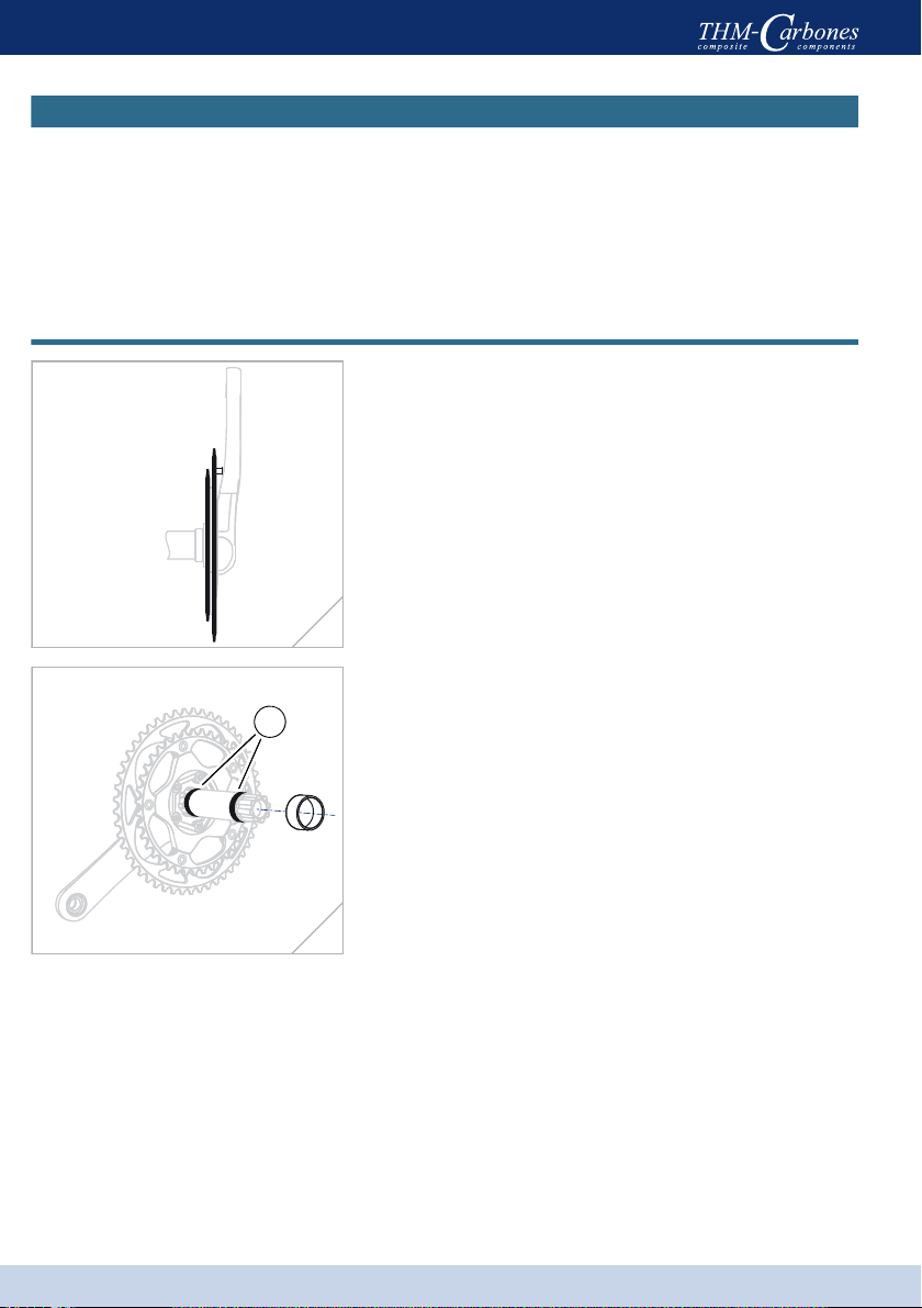
Installing the cranks
Insert the corresponding spacer ring onto the axle -
only when using the following bottom brackets:
BBright™ Direct Fit Road: 9.0mm.
BBright™ PressFit MTB: 4.0mm.
EVO386 Road: 1.0mm.
Lightly grease the bearing seat(1) of the axle.
(fig. 16)
15
1
16

19
Clavicula M³
Assembly
Insert the axle crank through the bottom bracket up
to its stop. (fig. 17)
Thoroughly degrease the axle and crank multi-tooth
segment.
Insert the spacer ring onto the axle.
Road: 2.5mm
MTB: 9.7mm
(fig. 18)
Fit the left-hand crank to the multi-tooth segment of
the axle.
Make sure the left and right-hand crank are seated
correctly!
Press the cranks together by hand up to the limit
stop.
Both cranks abut against the inner rings of the
bearings. (fig. 19)
Check the clearance between the cranks and the
chainstays of the frame.
Minimum crank to chainstay clearance: 3mm
17
Road MTB
18
19
20
Clavicula M³
Assembly
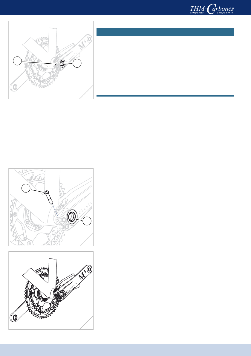
Adjusting the bottom bracket
NOTICE
Accelerated bearing wear if the bottom bracket is set
too rigidly due to excessive pre-tensioning of the ad-
justing screw.
-Only adjust the bottom bracket if the clamping
screw(1) has been loosened!
As a rule, the required tightening torque of the adjust-
ing screw(2) for a correctly adjusted bottom bracket
is approximately 0.3–1N·m (3–9lbf·in).
Screw the adjusting screw into the axis – when
doing this use the THM adjusting tool, the end of
the THM bottom bracket tool or, if necessary,
a suitable coin (such as a 1 Euro piece).
Tighten the adjusting screw carefully and slowly
until the bottom bracket does not exhibit any play,
but can still be turned easily by hand.
Adjustment of the bottom bracket is now complete.
(fig. 20)
Remove the clamping screw(1).
Apply a medium-strength thread lock (Loctite or
other similar substance) to the thread of the clamp-
ing screw.
Replace the clamping screw.
Tighten the clamping screw using a tightening
torque of 8N·m (71lbf·in).
Tighten the adjusting screw(2) using a tightening
torque of 6N·m (53lbf·in) to prevent it from becom-
ing lost during travel. (fig. 21)
Installation of your Clavicula component is now
complete.
(fig. 22)
12
20
1
2
21
22
Table of contents
Other THM Bicycle Accessories manuals


