thomann t.bone free solo User manual

free solo
Active Antenna Splitter
User Manual

Thomann GmbH
Hans-Thomann-Straße 1
96138 Burgebrach
Germany
Telephone: +49 (0) 9546 9223-0
Internet: www.thomann.de
31.08.2022, ID: 314056 (V4)

Table of contents
1 General notes............................................................................................................................................... 5
2 Safety instructions..................................................................................................................................... 6
3 Features and scope of delivery........................................................................................................... 8
4 Installation and starting up.................................................................................................................. 9
5 Connections and controls................................................................................................................... 12
6 Technical specications....................................................................................................................... 14
7 Protecting the environment.............................................................................................................. 16
Table of contents
free solo 3
Active Antenna Splitter

4free solo
Active Antenna Splitter

1 General notes
This user manual contains important information on safe operation of the device. Read and
follow all safety notes and all instructions. Save this manual for future reference. Make sure
that it is available to all persons using this device. If you sell the device, include the manual for
the next owner.
Our products are subject to a process of continuous development. We therefore reserve the
right to make changes without notice.
This section provides an overview of the symbols and signal words used in this user manual.
Signal word Meaning
DANGER! This combination of symbol and signal word indicates an
immediate dangerous situation that will result in death or
serious injury if it is not avoided.
NOTICE! This combination of symbol and signal word indicates a pos‐
sible dangerous situation that can result in material and
environmental damage if it is not avoided.
Warning signs Type of danger
Warning – danger zone.
Symbols and signal words
General notes
free solo 5
Active Antenna Splitter

2 Safety instructions
This device is used in wireless transmission systems to distribute and amplify the incoming
antenna signals. Use the device only as described in this user manual. Any other use or use
under other operating conditions is considered to be improper and may result in personal
injury or property damage. No liability will be assumed for damages resulting from improper
use.
This device may be used only by persons with sucient physical, sensorial, and intellectual
abilities and having corresponding knowledge and experience. Other persons may use this
device only if they are supervised or instructed by a person who is responsible for their safety.
Safety
DANGER!
Danger for children
Ensure that plastic bags, packaging, etc. are disposed of properly and are not within reach of babies and young children. Choking
hazard! Ensure that children do not detach any small parts (e.g. knobs or the like) from the unit. They could swallow the pieces and
choke! Never let children unattended use electrical devices.
Intended use
Safety instructions
6free solo
Active Antenna Splitter

NOTICE!
Operating conditions
This device has been designed for indoor use only. To prevent damage, never expose the device to any liquid or moisture. Avoid
direct sunlight, heavy dirt, and strong vibrations. Only operate the device within the ambient conditions specied in the chapter
‘Technical specications’ of this user manual. Avoid heavy temperature uctuations and do not switch the device on immediately
after it was exposed to temperature uctuations (for example after transport at low outside temperatures). Dust and dirt inside can
damage the unit. When operated in harmful ambient conditions (dust, smoke, nicotine, fog, etc.), the unit should be maintained by
qualied service personnel at regular intervals to prevent overheating and other malfunction.
NOTICE!
External power supply
The device is powered by an external power supply. Before connecting the external power supply, ensure that the input voltage (AC
outlet) matches the voltage rating of the device and that the AC outlet is protected by a residual current circuit breaker. Failure to do
so could result in damage to the device and possibly the user. Unplug the external power supply before electrical storms occur and
when the device is unused for long periods of time to reduce the risk of electric shock or re.
Safety instructions
free solo 7
Active Antenna Splitter

3 Features and scope of delivery
This appliance is used when multiple radio links are to be operated with a single antenna pair.
The following features characterize the device:
nAmplifying the high frequency signal of a pair of antennas and distribution to 4 × 2
antenna outputs in the frequency ranges of 470 MHz to 608 MHz, 614 MHz to 694 MHz,
823 MHz to 832 MHz and 863 MHz to 865 MHz.
nCentral 12 V power supply for up to four units
n19" rack mountable
Included accessories: 12 V power adapter, 2 UHF omni-directional antennas, 10 BNC cables.
Features and scope of delivery
8free solo
Active Antenna Splitter

4 Installation and starting up
Unpack and check carefully there is no transportation damage before using the unit. Keep the
equipment packaging. To fully protect the product against vibration, dust and moisture during
transportation or storage use the original packaging or your own packaging material suitable
for transport or storage, respectively.
Create all connections while the device is o. Use the shortest possible high-quality cables for
all connections. Take care when running the cables to prevent tripping hazards.
The unit has been designed for rack mounting in a standard 19-inch rack; it occupies one rack
unit.
Before you start, make sure that the frequencies of the connected wireless systems are legiti‐
mate in the respective country and check whether the operation must be registered with the
responsible authority. For further information on that refer to the manual of the wireless sys‐
tems.
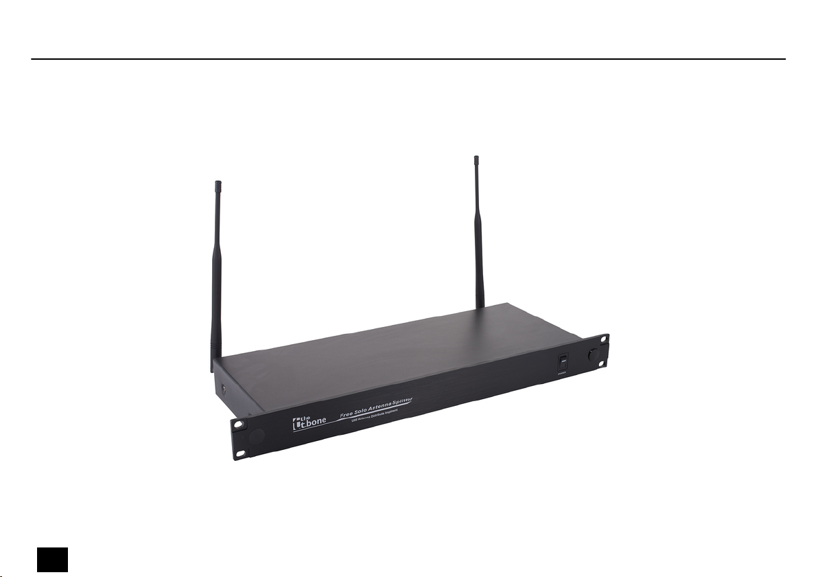
Attach the supplied antennas to appropriate positions, such as the PA rack. To improve the
transmission quality and to adapt to the spatial conditions, the antennas are rotatable and
swivelling. Position the antennas so that all used transmitters (e.g., wireless microphones,
body-pack transmitters) are within radio range. Install a BNC cable from both antennas to one
of the antenna inputs each of the device.
Rack mounting
Notes on radio transmission
Attaching and connecting
antennas.
Installation and starting up
free solo 9
Active Antenna Splitter

Connect one antenna output pair of the device each to the two antenna inputs of a wireless
system. To do so, use the supplied BNC cables.
NOTICE!
External power supply
The device is powered by an external power supply. Before connecting the
external power supply, ensure that the input voltage (AC outlet) matches the
voltage rating of the device and that the AC outlet is protected by a residual cur‐
rent circuit breaker. Failure to do so could result in damage to the device and pos‐
sibly the user.
Unplug the external power supply before electrical storms occur and when the
device is unused for long periods of time to reduce the risk of electric shock or
re.
Connect the 12 V outputs of the device to the 12 V power supply inputs of the wireless sys‐
tems. To do so, use the supplied power cords.
Connect the power adapter to the unit and then plug the power adapter into the power outlet.
Now switch on the device and the connected wireless systems.
Setting up the radio connection
Connecting the power supply
Taking system in operation
Installation and starting up
10 free solo
Active Antenna Splitter

The following illustration shows how to connect the device to the optionally available paddles
and to four wireless systems. Instead of the paddles, you can also connect the device to the
antennas included in the delivery.
Example
Installation and starting up
free solo 11
Active Antenna Splitter

5 Connections and controls
ö
1[POWER] | Main switch. Turns the device on and o.
Front panel
Connections and controls
12 free solo
Active Antenna Splitter

# % $
'( &
2, 3 [ANTENNA-A], [ANTENNA-B] | BNC chassis connectors for cable connection to the supplied UHF omni-directional
antennas.
4 Socket for connecting the supplied power adapter.
5, 6 [ANT-1] … [ANT-4] | BNC chassis connectors for cable connection to the connected wireless systems.
7[OUTPUT1] … [OUTPUT4] | Power supply connections for the connected wireless systems. The power supply for the
connected wireless systems is active even when the antenna splitter is o.
Rear panel
Connections and controls
free solo 13
Active Antenna Splitter

6 Technical specications
Input connections Power supply 1 × socket for connecting the plug-in power
supply
Antenna / booster 2 × BNC inputs (9V DC for active antennas /
booster)
Input impedance 50 Ω
Output connections Power supply of the connected wireless
systems
4 × DC out socket, 600 mA
Wireless systems 2 × BNC chassis socket
Output impedance 50 Ω
Frequency response 470 MHz … 608 MHz, 614 MHz … 694 MHz, 823 MHz … 832 MHz, 863 MHz … 865 MHz
Transmission power 15 dBm
Antenna gain 3 dB (+/–3 dB)
Power supply External power adapter, 100 - 240 V 50/60 Hz
Operating voltage 12 V…18 V / 3000 mA, centre positive
Installation 19", 1 RU
Technical specications
14 free solo
Active Antenna Splitter

Dimensions (W × H × D), without
antenna
410 mm × 45 mm × 160 mm
Weight 2 kg
Ambient conditions Temperature range 0 °C…40 °C
Relative humidity 20 %…80 % (non-condensing)
Component type Antenna splitter
Further information
Technical specications
free solo 15
Active Antenna Splitter

7 Protecting the environment
For the transport and protective packaging, environmentally friendly materials have been
chosen that can be supplied to normal recycling.
Ensure that plastic bags, packaging, etc. are properly disposed of.
Do not just dispose of these materials with your normal household waste, but make sure that
they are collected for recycling. Please follow the notes and markings on the packaging.
This product is subject to the European Waste Electrical and Electronic Equipment Directive
(WEEE) in its currently valid version. Do not dispose with your normal household waste.
Dispose of this device through an approved waste disposal rm or through your local waste
facility. When discarding the device, comply with the rules and regulations that apply in your
country. If in doubt, consult your local waste disposal facility.
Disposal of the packaging mate‐
rial
Disposal of your old device
Protecting the environment
16 free solo
Active Antenna Splitter

Notes
free solo 17
Active Antenna Splitter

Notes
18 free solo
Active Antenna Splitter


Musikhaus Thomann · Hans-Thomann-Straße 1 · 96138 Burgebrach · Germany · www.thomann.de
Other manuals for t.bone free solo
1
Table of contents
Other thomann Media Converter manuals
Popular Media Converter manuals by other brands

Interlogix
Interlogix IFS MC350-1T-2S user manual

Baumer
Baumer Hubner Berlin HMG 11 Mounting and operating instructions

Cobalt Digital Inc
Cobalt Digital Inc openGear 9035 owner's manual

Pacific Image Electronics
Pacific Image Electronics ImageBox MF quick reference

Baumer
Baumer HOG 10 G Installation and operating instructions

ANTAIRA
ANTAIRA FCU-6001-SFP+ user manual