Thomas Renegade TG-550H Manual

LIMITED WARRANTY
The Thomas Industries, Inc. Compressor is warrantied to you, the original purchaser,
for a period of one year from date of original retail purchase or 90 days, if used for
commercial or industrial use, to be free from defects in material or workmanship. If
during the specified warranty period you believe the purchased product of any part
thereof has such a defect, you must return the product or part during such period, with
proof of purchase and at your cost, to the nearest authorized service center (consult
the list of service centers enclosed with the product) for repair, or replacement of the
defective part. If you do not know the location of the nearest service center, contact
Thomas Industries at the address below for instructions. If the product or part is found
to have been defective in material or workmanship, it will be repaired or replaced (as
deemed necessary by the repair center), free of charge, and returned to the purchaser
at purchaser’s cost. If repair work must be done at the Thomas Industries factory,
transportation costs of the product or part to and from the factory must be paid by the
purchaser.
This warranty shall not apply to any compressor which in Thomas’ judgement has
been subject to misuse, negligence or accident, or which has been operated from a low
power supply. This warranty shall not apply to compressors that require oil for operation
which have been operated with oil levels below that specified by Thomas Industries.
THE MANUFACTURER LIMITS THE DURATION OF THE IMPLIED WARRANTY OF
MERCHANTABILITY TO THE LIMITED WARRANTY PERIOD SET FORTH ABOVE,
AND OTHERWISE DISCLAIMS ALL IMPLIED WARRANTIES WITH RESPECT TO
THE PRODUCT AND IT’S PARTS. Some states disallow certain limitations on implied
warranties. You should consult your state law if you have a question regarding this
limitation and disclaimer.
THE MANUFACTURER DISCLAIMS ANY AND ALL LIABILITY FOR INCIDENTAL,
CONSEQUENTIAL, SPECIAL OR INDIRECT DAMAGES ARISING OUT OF ANY
CLAIMED BREACH OF WARRANTY OR OTHERWISE. HOWEVER, SOME STATES
DO NOT ALLOW EXCLUSION OR LIMITATION OF SUCH DAMAGES, SO THIS
DISCLAIMER MAY NOT APPLY TO YOU.
The remedy provided in this Limited Warranty for a defective product is purchaser’s
sole and exclusive remedy, subject to your state law. Further, this Warranty gives you
specific legal rights, and you may also have other rights which vary from state to state.
If you believe warranty service is needed, contact your nearest authorized service
center. If one does not exist in your area, please contact the manufacturer:
Thomas Industries, Inc.
C/O Customer Service
1419 Illinois Avenue
Sheboygan, Wisconsin 53082
Phone: (920) 457-4891
Fax: (920) 451-6307
www.thomasairpac.com
OWNER’S MANUAL and OPERATING INSTRUCTIONS for
TG-550H
1419 ILLINOIS AVE., SHEBOYGAN, WI 53082 USA
Performance, portability, and reliability makes the RENEGADE TG-550
Series our finest, most convenient gas powered compressors. They are
ideal for use in applications requiring a heavy-duty compressed air source
in areas where an electrical connection is not available.
• 5.5 HP HONDA OHV GASOLINE ENGINE
• WOBL PISTON COMPRESSOR
• PERMA-LUBE™ COMPRESSOR DESIGN
• 7 GALLONS AIR STORAGE
• 12 CFM @ 100 PSI
Part No. 642501 Rev O 10/05 ©2005 Thomas Industries Sheboygan Inc., Printed in U.S.A.
All Rights Reserved
SPECIFICATIONS
Air Displacement....................................................................24CFM (680 LPM)
Air Delivery.............................12cfm @ 100 PSI..............340 LPM @ 690 kPa)
Safety Valve Setting.............................................................165 PSI (1140 kPa)
Engine Idle Speed..................................................................2200 ± 150 RPM
Engine Run Speed.................................................................3450 ± 150 RPM
Automatic Control............................................Continuous Run Unloader Valve
....................................................Unloads @ 135 PSI (930 kPa)
........................................................Loads @ 115 PSI (795 kPa)
Engine Oil-Recommended....................................See Engine Owner’s Manual
Air Tank Capacity, .............................................................................. 7 Gallons
Unit Weight ................................................................................100 lbs. (46 kg)
Unit Dimensions LxWxH (in).............43 X 18 X 23 (cm).............110 X 46 X 59
Compressor Type...........................Oilless Compressor, Perma-Lube™ Design
Pump-Up Time ........................................................................ Approx. 1.0 Min.
Recovery Time ..............................................................Approx. 8 ± 3 Seconds
Regulator Connection Size..................................................................1/4 - NPT
CFM = Cubic Feet Per Minute kPa = kilopascals PSI = Pounds Per Square Inch
RPM = Revolutions Per Minute LPM = Liters Per Minute

1. The compressor should be located in a dry, clean,and well ventilated area.
2. Inspect before use for signs of damage. Do not use if a deficiency is
found. Contact your nearest service center for replacement parts. Never
operate a damaged unit.
3. Do not tamper with safety valve as it has been factory set. Any ad-
justment of this valve could cause serious injury.
4. Compressed air must never be aimed at anyone because it can cause
serious injury. Keep children away. WEAR EYE PROTECTION.
5. All air compressors generate heat under normal operating conditions. To
avoid serious burns, never touch the air compressors during or immedi-
ately after operation.
6. Never run engine indoors or in enclosed, poorly ventilated areas. Engine
exhaust contains carbon monoxide, an odorless and deadly gas.
7. Before servicing, cleaning, or removal of any part, stop engine and relieve
air pressure.
8. This system produces 135 PSI. To avoid rupture and injury, do not operate
this compressor with components rated less than 135 PSI working pres-
sure.
9. Keep hands, feet, hair, and loose clothing away from any moving parts on
engine, and compressors.
10. Do not tamper with the engine speed or air/fuel mixture. These items
have been factory set.
If warranty service or repairs are needed, contact your nearest au-
thorized service center. If one does not exist contact the factory. Unau-
thorized repairs or teardown of the unit will void the factory warranty.
Read and understand the information in this owner’s
manual and the engine owner’s manual before operat-
2 19
This symbol points out important safety instructions which
if not followed could endanger the personal safety and/or
property of yourself and others.
NOTES

SETUP
NOTE: The engine is shipped without oil. Add oil before use. It is recom-
mended that you change the oil as described in your engine owner’s manual
maintenance schedule. Always check the oil level before starting engine.
(See engine owner’s manual for oil and fuel recommendations.)
STARTING ENGINE
1. Turn fuel valve to the “ON” position.
2. Flip the engine switch to the “ON” position.
3. Place foot on base, grasp starter handle, and start engine as you would
a lawn mower. Use choke if necessary.
STARTING ENGINE AGAINST PRESSURIZED TANKS
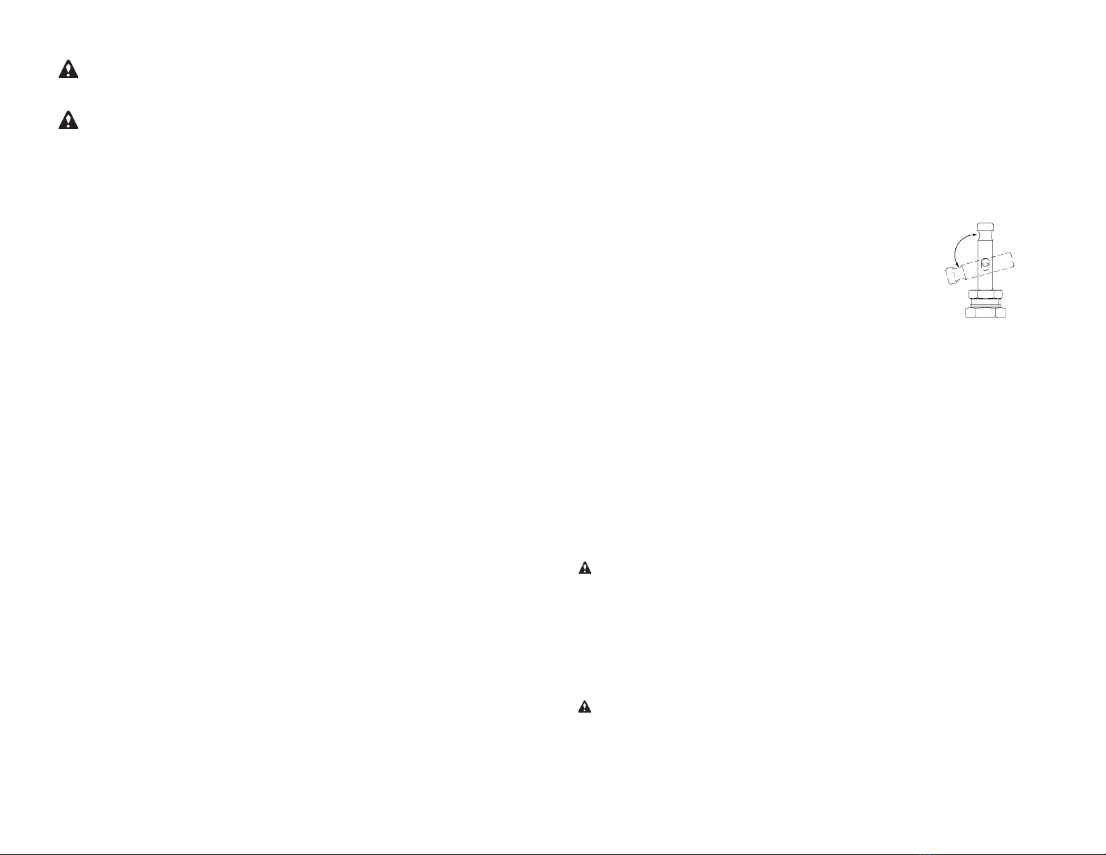
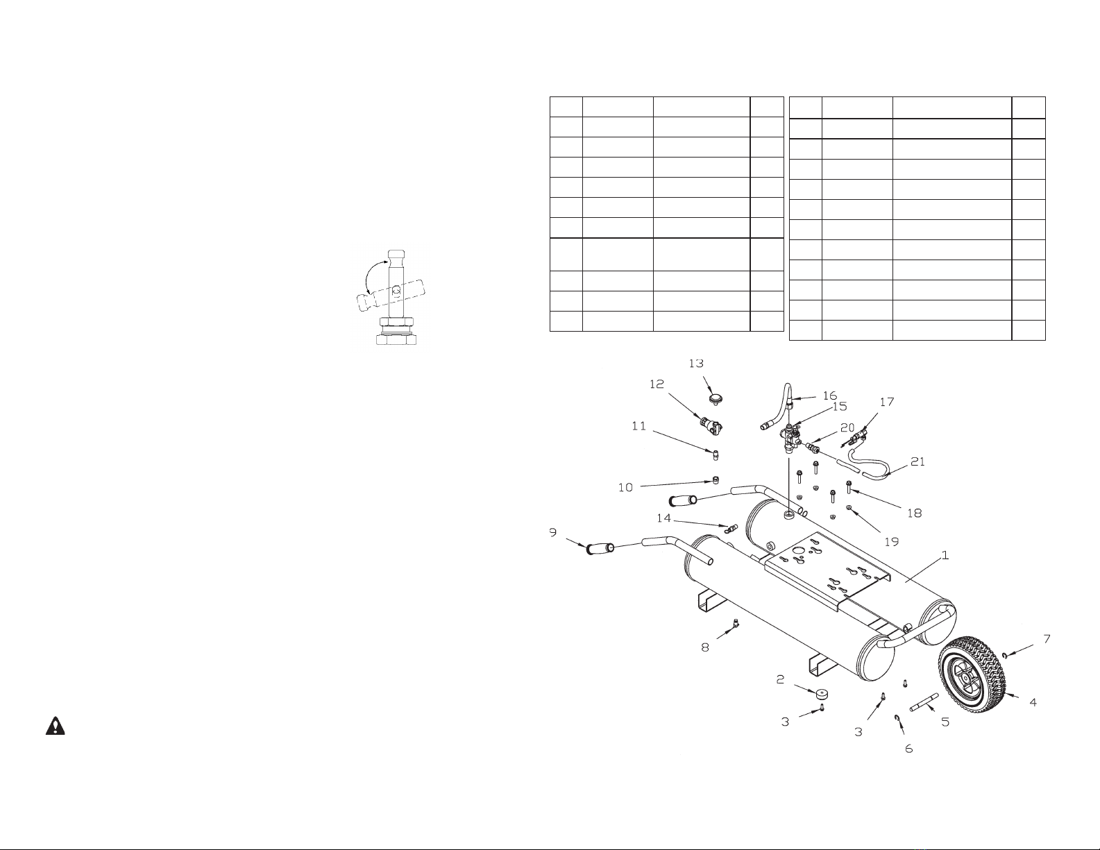
MANUAL UNLOADER VALVE
1. Move to “UNLOAD” position
2. Start engine
3. Return to “PRESSURIZE” position
When STARTING the engine with air pressure in the tanks (i.e. after refu-
eling, etc.), manually unload the compressors by moving the valve to the
“UNLOAD” position, starting the engine, and then moving the valve back to
the “Pressurize” position. This allows the compressors to turn freely (ex-
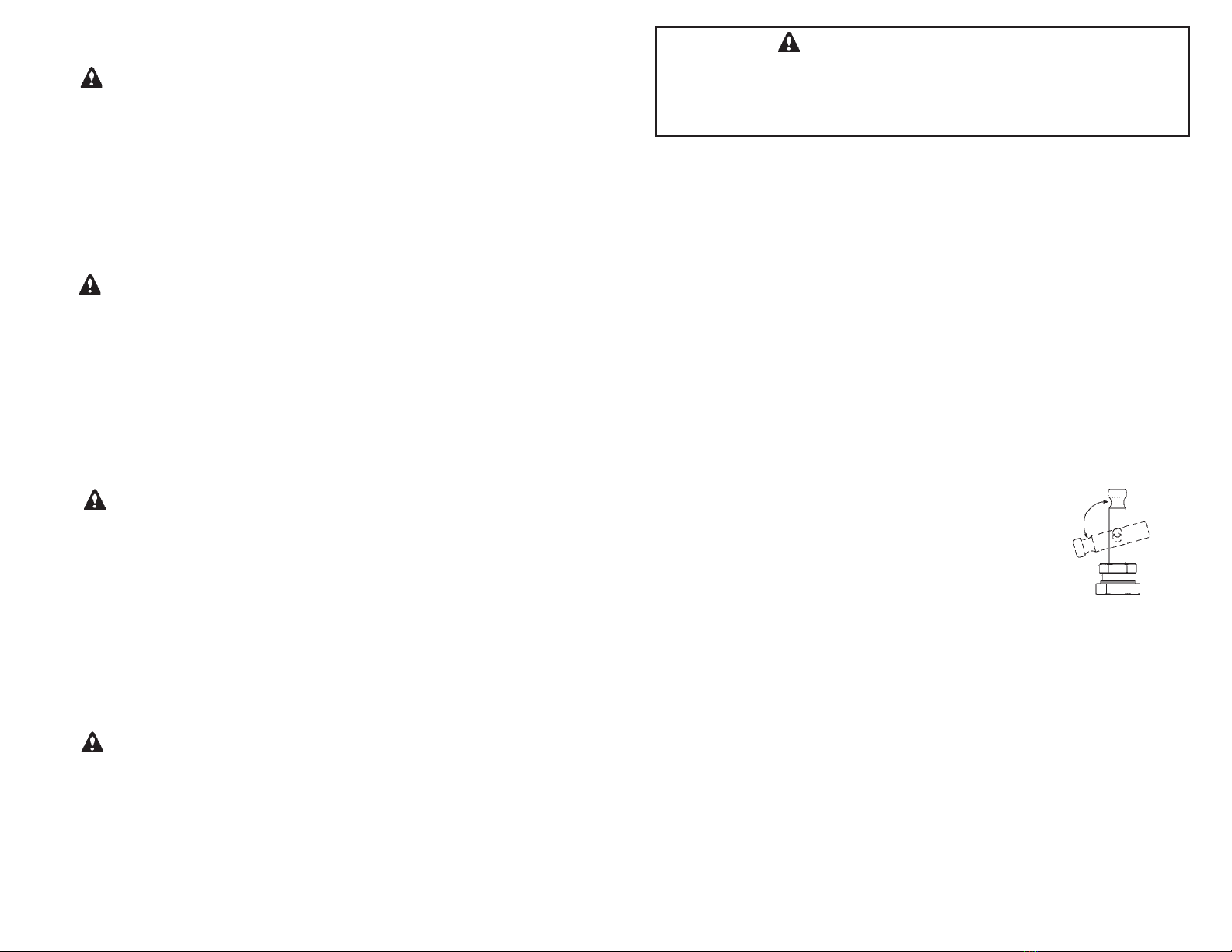
haust to atmosphere) without the back pressure of the tanks. To clean vent,
remove the nut containing screen and filter with a 11/16”hex wrench. Hold
under running tap water with nut toward faucet. Shake out excess water and
reinstall.
OPERATION
The engine will start with the control lever in the “FAST’ position and will
compress air until the tank pressure reaches 135 PSI. When the tank pres-
sure reaches 135 PSI, the unloader valve will automatically actuate the
throttle control causing the engine to run at idle speed, and vent the com-
pressed air to atmosphere. When the tank pressure drops to 115 PSI, the
unloader valve will reactuate the throttle control, causing the engine to run at
high speed, and redirect the compressed air to the tank.
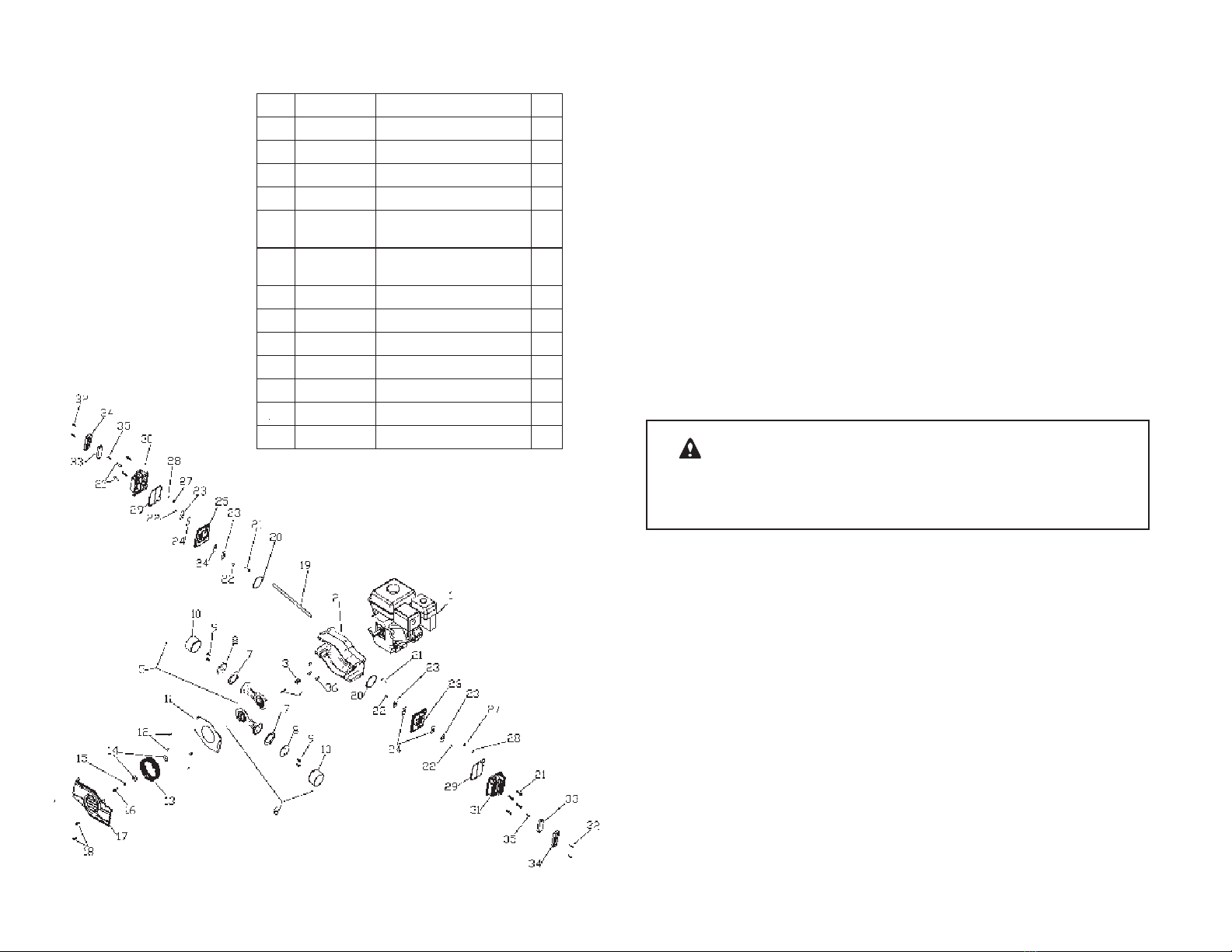
WARNING: Before using air tools or accessories, check manufacturer’s
maximum pressure rating. Maximum pressure rating must be above 135
PSIG.
STOPPING
1. Flip the engine switch to the “OFF’ position.
2. Release air from tank.
3. Drain water from both tanks.
4. Turn fuel valve to “OFF” position.
5. Drain excess gas if compressor is to be stored indoors. (see engine own-
ers manual).
WARNING: To avoid risk of tank failure during use, drain tank after each
use or every four (4) operating hours to prevent condensation build up and
corrosion inside tanks. To drain tank, slowly and carefully turn and open
drain fittings, tip unit towards drain, and allow water to drain out.
NOTE: When draining tank, watch for debris (rust particles). If there appears
to be debris in the water, contact your dealer for possible tank replacement.
UNLOAD
PRESSURIZE
3
PRECAUCION: Nunca limpie el filtro de aire con un solvente o líquido
inflamable. Se pueden acumular vapores explosives en el tanque de aire y
causar una explosión, lo queresulta en serias heridas o la muerte.
PRECAUCION: No opere el compresor de aire sin el filtro de aire.
MAQUINA
Consulte el manual del propietario de la máquina para los procedimientos
de mantenimiento apropiados.
NOTA: Desconecte el cable de la bujía antes de dar servicio a la máquina o
a los compresores.
GARANTIA DE LA MAQUINA Y REPARACIONES
Los ajustes de la máquina, reparaciones y servicio de garantía se deben
manejar por medio de sus centros de servicio autorizados del fabricante de
su máquina. Están enlistados en la sección amarilla de su directorio tele-
fónico bajo “máquinas, gasolina”.
ESPECIFICACIONES
Desplazamiento de Aire .................................................. 24 CFM (680 LPM)
Rendimiento de Aire ........... 12 CFM a 100 PSI........... (340 LPM a 690 kPa)
Ajuste de la Válvula de Seguridad .................................. 165 PSI (1140 kPa)
Velocidad de Marcha en Vacío de la Máquina .................... 2200 ± 150 RPM
Velocidad de Marcha de la Máquina ................................... 3450 ± 150 RPM
Control Automático ..................... Válvula descargadora de Marcha Continua
............................................. Descarga a 135 PSI (930 kPa)
................................................Carga a 115 PSI (795 kPa)
Aceite para Máquina-Recomendado .............................. Consulte el Manual
del Propietario de la Máquina
Capacidad delTanque deAire......................................................... 7 Galones
Peso de la Unidad .................................................................100 lbs. (46 kg)
Dimensiones de la Unidad LxAxA LxWxH (in)............................43 X 18 X 23
(cm)..........................110 X 46 X 59
Tipo de Compresor .......................................... Compresor sin Aceite Diseño
PermaLube™
Tiempo de bombeo.......................................................................... ... 60 Seg
Tiempo de Recuperación................................................................ 8 ± 5 Seg
Tamaño de la Conexión del Regulador ............................................. 1/4 NPT
CFM = Pies Cúbicos Por Minuto RPM = Revoluciones por Minuto
LPM = Litros Por Minuto kPa = kilopascales
PSI = Libras Por Pulgada Cuadrada
18

WARNING: Do not weld on the air tanks of this compressor. Welding on
the air compressor tank can severely impair tank strength and cause an
extremely hazardous condition. Welding on the tank in any manner will void
the warranty. If warranty service or repairs are needed contact your nearest
authorized service center. If one does not exist contact the factory. Unauthor-
ized service of the unit will void the factory warranty.
MAINTENANCE
AIR FILTER - COMPRESSORS
Inspect compressor air filters regularly. Clean filter with soap and water as
necessary. If filter becomes clogged or damaged, replace it.
WARNING: Never clean air filter with a flammable liquid or solvent. Explo-
sive vapors may accumulate in the air tank and cause an explosion, resulting
in serious injury or death.
CAUTION: Do not operate air compressor without air filter.
CONTROL VALVE
The control valve is preset at the factory to load at 115 psi and unload at 135
psi and should not require adjustment. If adjustment is necessary the unload
pressure is adjusted by slightly turning the pressure adjusting nut (9/16” Hex)
while holding the locking nut (5/8” Hex). Turn clockwise to increase, and coun-
terclockwise to decrease the unload pressure. Changing the differential (the
difference between the load and unload pressure) is accomplished by holding
the locknut (7/8” Hex) closest to the body of the valve (so it does not move)
then turning the (3/4” Hex) nut next to it very slightly clockwise to increase the
differential, and counterclockwise to decrease it.
ENGINE
Refer to engine owner’s manual for proper maintenance procedures.
NOTE: Disconnect spark plug wire before servicing engine or compressors.
ENGINE WARRANTY AND REPAIRS
Engine adjustments, repairs, and warranty service are to be handled through
your engine manufacturer’s authorized service centers. They are listed in your
telephone book yellow pages under “ENGINES, GASOLINE”.
4 17
APAGADO
1. Mueva el interrupter de la máquina a la posición de “APAGADO” (OFF, en
inglés).
2. Saque el aire del tanque.
3. Drene el agua de ambos tanques.
4. Gire la valvula de combustible a la posicion de “APAGADO” (OFF in
Ingles).
5. Drene el exceso de gasolina si el compresor se va a almacenar en un
lugar interior (vea el manual del propietario de la máquina).
PRECAUCION: Para evitar el riesgo de falla del tanque durante su uso,
drene el tanque después de cada vez que se use o cada cuatro (4) horas
de operación para evitar el acumulamiento de condensacion y la corrosión
dentro de los tanques.
Para drenar el tanque, abra las valvulas de drenaje despacio y con cui-
dado. Incline la unidad hacia la valvula y espere hasta que el agua salga del
tanque.
NOTA: Cuando drene el tanque, tenga cuidado con desechos (partículas de
óxido). Si parece que hay desechos en el agua, comuníquese con su distri-
buidor para la posibilidad de reemplazar el tanque.
PRECAUCION: No solde en los tanques de aire de este compresor. El
soldar en el tanque compresor de aire puede dañar severamente la resisten-
cia del tanque y causar una situación extremadamente peligrosa. El soldar
en el tanque de cualquier manera nulificará la garantía. Si necesita servi-
cio de garantîa o si necesita reparaciones, comuníquese con su centro de
servicio autorizado mas cercano. Si no existe alguno, comuníquese con la
fábrica. El desmantelamiento de launidad no autorizado nulificará la garantía
de fabrica.
MANTENIMIENTO
FILTRO DE AIRE - COMPRESORES
Inspeccione los filtros de aire del compresor regularmente. Limpie el filtro con agua y
jabón cuando sea necesario. Si el filtro se tapa o se daña, cámbielo.
VALVULA DE CONTROL
La valvula de control es fijada de fabrica para cargar el tanque a 115 psi y para
descargar a 135 psi, y no debe requerir ajuste. Si ajuste es necesario. la presion
de descarga es ajustada al girar ligeramente la tuerca de ajuste de presion (9/16”
hexagonal) mientras se sostiene la tuerca de seguridad (5/8” hexagonal). Gire en
el sentido de las manecillas del reloj para incrementar y en sentido opuesto para
disminuir presion de carga. El cambio del diferencial (la diferencia entre la presion de
carga y descarga) se logra sosteniendo la tuerca de seguridad (7/8” hexagonal) cerca
del cuerpo de la valvula (para que no se mueva), despues girando la tuerca (3/4”
hexagonal) muy despacio en sentido de las manecillas del reloj para disminuirlo.

5
Key Part No. Description Qty.
1 662975-540 Tank Ass’y 1
2 624654 Bumper 4
3 625406 Screw 1/4-14 6
4 647226 Wheel 1
5 629205 Axle 5” 1
6 623601 Retaining Ring 1
7 623614 Retaining Ring 1
8 624273 Drain Cock Ass’y 2
9 604229 Hand Grip 2
10 Not Used
TANK ILLUSTRATION AND PARTS LIST
16
PARA ARRANCAR LA MÁQUINA CONTRA
TANQUES PRESURIZADOS
VÁLVULA DE DESCARGA MANUAL
1. Mueva a la posición de “DESCARGAR” (UNLOAD, en inglés)
2. Arranque la máquina
3. Regrese a la posición de
“PRESURIZAR” (PRESSURIZE, en inglés)
Cuando ARRANQUE la máquina con aire a presión en los tanques (por
ejemplo, después de cargar combustible, etc), descargue los com-
presores manualmente moviendo la válvula a la posición de “DESCAR-
GAR”, arranque la máquina y luego
regrese la valvula a la posición de “PRESION” (PRESSURE, en inglés).
Esto permite que los compresores den vueltas libremente (con escape a
la atmósfera) sin la contrapresion de los tanques).
OPERACION
La máquina arrancará con la palanca de control en la posición de
“RAPIDO” (Fast, en inglés) y comprimirá el aire hasta que la presión del
tanque alcance 135 PSI. Cuando la presión del tanque alcanza 135 PSI,
la válvula de descarga automáticamente activará el control de la impul-
sión, lo que causará que la máquina corra a una velocidad en vacío y
ventile el aire comprimido a la atmósfera. Cuando la presión del tanque
disminuye a 115 PSI, la válvula de descarga reactivará el control de la
impulsión, lo que causará que la máquina corra a alta velocidad y dirija el
aire comprimido al tanque.
PRECAUCION: Antes de usar herramientas de aire o accesorios,
revise la clasificación de presión máxima del fabricante. La clasificación
de presión máxima deberá de estar por arriba de 135 PSIG.
PRESURIZAR
DESCARGAR
Key Part No. Description Qty.
11 624925 Fitting 2 x 1/4”-18 NPT 1
12 641133 Regulator 1
13 638262 Pressure Gauge 2
14 638975 Safety Valve 165 PSI 1
15 638835 Valve - Unloader 1
16 615937 Hose - Stainless Steel 1
17 638927 Throttle Control - 18” 1
18 625823 Screw 5/16-18 x 1.5” 4
19 626831 Nut 5/16-18 4
20 624767 Fitting 1
21 615881 Tube - Throttle 1

615
Key Part No. Description Qty.
1 643317 Engine-Honda 5.5HP 1
2 669115-540 Housing-Black 1
3 627247 Spring .75 ID X 1.0 L 1
4 626866 Key, Square - 3/16 x 1.8 1
5 666931 ConnRod, Ecc, Sleeve &
Brg. Assy. (Inner) 1
6 666932 ConnRod, Ecc, Sleeve &
Brg. Assy. (Outer) 1
7 626183 Piston Cup 2
8 626190 Retainer 2
9 625170 Screw 1/4-20 x .88 4
10 618193 Cylinder Sleeve 2
11 662805 Deflector Cover 1
12 625192 Screw 10-24 x .5 Pan Hd. 4
13 638891 Fan - Blower Wheel 5’’ 1
Si se requieren reparaciones o servicio de garantia, póngase en con-
tacto con el centro de servicio autorizado más cercano. Si no dispone
de un centro, póngase en contacto con la fábrica. Las reparaciones,
o el desmontaje de la unidad sin autorización anularán la garantía de
fábrica.
• MAQUINA DE GASOLINA DE 5.5 CABALLOS DE FUERZA
• 18 GALONES DE ALMACENAMIENTO DE AIRE (HBT)
• 7 GALONES DE ALMACENAMIENTO DE AIRE (H)
• 12 CFM A 100 PSI
• COMPRESOR DE PISTONES WOB-L®
• DISEÑO PERMA-LUBE™
El rendimiento, la transportabilidad y la seguridad hacen del REN-
EGADE TG-550 nuestro mejor y mas conveniente compresor operado
con gasolina. Es ideal para usarse en aplicaciones que requieran de
una fuente de aire comprimido de alto poder donde una conexión eléc-
trica no se encuentra disponible.
Este simbolo señala importantes instrucciones de seguridad las
cuales si no se siguen, pueden, poner en peli gro la seguridad personal
y/o las pertenencias de usted y otros. Lea y entienda la información en
este manual del propietario y el manual del propietario de la máquina
antes de ponerse en operación.
Lea y entienda la información en este manual del propietario y el
manual del propietario de la máquina antes de ponerse en operación.
PREPARACION
NOTA: La máquina ha sido enviada sin aceite. Agréguele aceite antes
de usarla. Se recomienda que cambie el aceite como se describe en
el plan de mantenimiento del manual del propietario de la máquina.
Siempre cheque el nivel del aceite antes de echar a andar la máquina.
(Vea el manual del propietario de la máquina sobre recomendaciones
para aceite y combustible.)
PARA ARRANCAR LA MÁQUINA
1. Ponga la válvula de combustible en ON (encendido).
2. Mueva el interruptor de la máquina a la posición de“ENCENDIDO”
(ON, en inglés).
3. Coloque el pie en la base, sujete el mango de arranque y arranque
la máquina como si arrancara una segadora de pasto.

714
FOR SERVICE AND PARTS
For service contact the dealer from whom you purchased the
compressor. To order parts, visit us on line at
www.thomasairpac.com or phone our customer service center at
1-800-558-7721.
COMPRESSOR ILLUSTRATION AND PARTS LIST
PRECAUCION: Antes de operar el compressor de aire, lea este
manual del propietario y asegurese de comprender la informacion aqui
contenida.
1.EI compresor debe ubicarse en una zona seca, limpia y bien venti-
lada.
2. Inspeccione el compressor antes de su uso. No se use si se encuen-
tra una deficiencia o senales de dano. Contacte a su centro de servicio
mas cercano para obtener partes de repuesto.
3. El ajuste de la valvula de alivio de seguridad ha sido fijado en la
fábrica. No lo altere. Los ajustes de esta valvula pueden provocar
lesiones graves.
4. El flujo de aire comprimido no debe dirigirse a ninguna persona
porque puede provocar lesiones graves. No permitaque se acerquen
los niños. UTILICE PROTECTORES PARA LOS OJOS.
5.Todos los compresores de aire generan calor, aun bajo condiciones
de operación normales. Para evitar quemaduras graves no toque el
cabezal ni los componentes del escape del compresor durante la oper-
ación o inmediatamente después de ella.
6. Nunca opere el motor en interiores o areas con poca ventilacion.
Los gases de escape del motor contienen monoxido de carbono, un
gas inodoro y letal.
7. Antes del servicio, la limpieza o el desmontaje de cualquier pieza,
ague la unidad y alivie la presion.
8. Este sistema puede producir hasta 9,5 kg/cm2 (135 psi). Para evitar
rupturas de componentes y lesiones, no opere la unidad con accesorios
cuya presion nominal de trabajo sea inferior a 9,5 kg/cm2 (135 psi).
9. Mantenga las manos, pies, cabello y ropa floja alejados de las piezas
en movimiento del compresor y de la máquina.
10. No altere la velocidad del motor o la mezcla de aire-combustible.
Esos parametros han sido fijados de fabrica.
REGLAS PARA UNA OPERACION SEGURA
Key Part No. Description Qty.
14 626274 Washer 2
15 626035 Lockwasher 1
16 625275 Screw 5/16 x .88 1
17 662412-450 Front Cover - Black 1
18 625172 Screw 1/4-20 x .75 4
19 615671 Tube 1
20 623075 O-Ring 2
21 623171 Screw 1/4-20 x 01.25 10
22 623278 Screw 10-32 x .38 4
23 617497 Restraint 4
24 662563 Valve 4
25 662822 Valve Plate-Acrylic Coat 1
26 662823 Valce Plate-Acrylic Coat 1
27 623096 O-Ring 2
28 623155 Retaining Ring 2
29 623082 O-Ring - Head Gasket 2
30 662501 Head - Burgandy 1
31 662619 Head - Burgandy 1
32 625646 Scrw 10/24 x .88 4
33 664142 Filter Element 2
34 664141 Cover - Filter 2
35 625198 Screw 10-24 x .88 2
36 625824 Screw 5/16-24 x .75 3

813
MOTERU
Se reporter au manuel du moteur pour les procédures correctes
d’entretien.
REMARQUE: Débranchez ie fil de la bougie avant de faire l’entretien du
moteur, de la courroie ou des compresseurs.
GARANTIE ET REPARATIONS DU MOTEUR
Les réglages, réparations et service de garantie du moteur doivent être
effectués par les centres de service agréés du fabricant du moteur. Vous en
trouverez la liste dans votre annuaire téléphonique à la rubique “Moteur à
essence”.
SPÉCIFICATIONS
Déplacement d’air............................................................ 24 CFM (680 LPM)
Débit d’air ..........................12 CFM à 100 PSI...............(340 LPMà 690 kPa)
Reglage de la valve de securite ..................................... 165 PSI (1140 kPa)
Vitesse de ralenti du moteur ..................................... 2200 ± ou - 150 RPM
Vitesse de marche du moteur..................................... 3450 ± ou - 150 RPM
Commando automatique Valve de déchargeur en marche continue
...............................Décharge à 135 PSI (930 kPa)
...................................Charge à 115 PSI (795 kPa)
Hulle de moteur recommandée ............................ Voir ie manuel du moteur
Volume des réservoirs d’air .............................................................. 7gallons
Poids de la machine ..............................................................100 lbs. (46 kg)
Dimensions Long. x larg. x haut. (pouces)................................ 43 x 18 x 23
(cm) .....................................110 x 46 x 59
Type de compresseur ............................Compresseur sans huileConception
PermaLube™
Temps de pompage .................................................... 60 ± ou-5 secondes
Temps de récupération ............... .................................8 ± ou - 3 sec-
ondes
Dimension de la connexion du régulateur ....................... 1/4 de pouce NPT
CFM = Pieds cubiques par minute
LPM = Litres par minute
PSI = Livres par pouce carré
kPa = kilopascals
RPM = Tours par minute
ATTENTION: Veuillez lire attentivement ce manuet d’utilisation avant de vous
servir de ce compresseur d’air.
1. Le compresseur doit être utilisé dans un endroit sec, pro et bien aéré.
2. Avant l’emploi, examiner le tuyau, la fiche et le fil électrique pour repére tous
signes de déterioration. Ne pas utiliser l’appareil en cas de défaut de fonc-
tionnement ou de matériel. Addressez-vous au service entretien le plus proche
pour obtenir des pieces de rechange. Ne jamai sutiliser un appareil défectueux.
3. Ne pas modifier la pression de la soupape de sûreté: elle a été reglée en
usine. Tout autre réglage pourrait entráiner un risque de blessure grave.
4. L’air comprimé ne doit jamais être pointé sur une personne, car il peut entráin-
er des blessures graves. Eloigner les enfants de l’endroit de travail. PORTER
DES LUNETTES DE PROTECTION.
5. Tous les compresseurs d’air produisent de la chaleur, même dans des condi-
tions de fonctionnement normales. Afin d’éviter les brûlures, ne jamais toucher le
compresseur d’air pendant ou tout de suite aprés utilisation.
6. AVANT D’UTILISER, DE NETTOYER OU DE RETIRER TOUT ACCESSOIRE,
DEBRANCHER L’APPAREIL ET REDUIRE LA PRESSION.
7. CE SYSTEME PEUT PRODUIRE 9,5 kg/cm2 (135 PSI). POUR EVITER
TOUTE RUPTURE POUVANT ENTRAINER DES BLESSURES, NE PAS
UTILISER CETTE POMPE AVEC DES ACCESSOIRES PREVUS POUR UNE
PRESSION INFERIEURE A 9,5 kg/cm2 (135 psi) (Y COMPRIS MAIS NON
LIMITE AUX PISTOLETS A PEINTURE.TUYAUX ET RACCORDS DESTUYAUX.
8. Ne faites jamais marcher le moteur à l’intérieur ou dans endroits mal aérés. Le
moteur laisse échapper de l’oxyde de carbone, un gaz mortel sans odeur.
9. Gardez mains, pieds, cheveux et vêtements flottants à distance des parties
mobiles du moteur et du compresseur.
10.Ne changez pas la vitesse du moteur et ne touchez pas aux controôes de
mélange d’air/carburant. Ceux-ci out été réglés en usine.
• MOTEUR À ESSENCE DE 5,5 CV
• RÉSERVOIR D’AIR DE (HBT)18 GAL./ (H) 7 GAL.
• 12 CFM @100 PSI
• CONCEPTION PERMA-LUBE™
Performance mobilité et fiabilité font de RENEGADE® TG-550 le meilleur et le
plus commode de nos compresseurs à moteur essence. Idéal dans les applica-
tions exigeant une source d’air comprime très puissante dans des lieux où n’y a
pas d’électricité.
PRECAUTIONS D’EMPLOI

9
12
Ce symbole . . . =
Ce symbole est là pour indiquer d’importantes instructions de sécurité qui peu-
vent mettre en danger votre sécurité et celle des autres ainsi que votre propriété
et/ou celle des autres si elles ne sont pas suives. Lire et comprendre les informa-
tions se trouvant dans ie manuel de l’utilisateur et dans ie manuel du moteur avant
de faire marcher cet appareil.
Lire et comprendre les informations se trouvant dans ie manuel de l’utilisateur et
dans ie manuel du moteur avant de faire marcher cet appareil.
AVANT LA MISE EN ROUTE
NOTE: Le moteur est expédié sans huile. Mettez de l’huile avant de l’utiliser.
II vous est recommandé de changer l’huile comme indiqué dans le calendrier
d’entretien de votre manuel du moteur. Toujours vérifier le niveau d’huile avant de
mettre en route le moteur. (Voir le manuel du moteur pour les recommandations en
matière d’huile et de carburant).
DÉMARRAGE DU MOTEUR
1. Ouvrez la valve de carburant (ON).
2. Mettre la clé de contact du moteur sur “ON” (marche).
3. Placer le pied sur la base de la machine, prendre la poignée
du démarreur et demarrer le moteur comme vous le (eriez
avec une tondeuse.
DÉMARRAGE DU MOTEUR CONTRE LES RÉSERVOIRS RESSURI-
SÉS
VALVE MANUELLE DU DECHARGEUR
1. Mettre sur “UNLOAD” (Décharger)
2. Mettre en route le moteur
3. Revenir sur “PRESSURIZE“ (Pressuriser)
“UNLOAD” = Décharger
“PRESSURIZE” = Pressuriser
Lorsque VOUS DÉMARREZ le moteur avec de la pression
d’air dans les réservoirs (par exemple, après avoir fait le plein,
etc. . . . ), déchargez manuellement les compresseurs en met-
tant la valve sur “UNLOAD” (Décharger), en démarrant le moteur et ensuite en
remettant la valve sur “PRESSURE” (Pression). Cela permet aux compresseurs de
tourner librement (évacuation à l’air libre) sans la pression des réservoirs.
FONCTIONNEMENT
Le moteur démarrera avec le levier de contrôle sur FAST (Rapide) et comprimera
l’air jusqu’à ce que la pression du réservoir atteigne 135 PSI. Lorsque la pression
du réservoir atteint 135 PSI, la valve du déchargeur activera automatiquement la
commande de l’accelerateur mettant le moteur au ralenti et éventera l’air compri-
mé dans l‘atmosphere. Lorsque la pression du réservoir tombe à 115 PSI, la valve
du déchargeur activera la commande d’accélératuer, ce qui fera tourner le moteur
à vitesse élevée et redirigera l’air comprimé dans le réservoir.
Décharger
Pressuriser
AVERTISSEMENT: Avant d’utiliser des outils ou des accessoires à air com-
primé, vérifier la pression maximum mentionnée par le fabricant. Cette pression
maximum doit être supérieure à 135 PSIG.
POUR ARRETER LE MOTEUR
1. Mettre la clé de contact sur “OFF” (Arrêt).
2. Relácher l’air du réservoir.
3. Vidanger l’eau des deux réservoirs.
4. La valve du combustible du tour à “FERMÉ” place.
5. Vidanger l’excés d’essence, si le compresseur doit être remisé à l’intérieur d’un
bâtiment (voir ie manuel du moteur).
AVERTISSEMENT: Pour éviter le risque de panne de réservoir pendant
l’usage, vidanger le réservoir après chaque utilisation ou toutes les quatre (4)
heures de marche pour empêcher l’apparition de condensation et de corrosion à
l’intérieur des réservoirs.
Pour vidanger un réservoir, tourner lentement et soigneusement les bouchons de
vidange. Incliner la machine du côté de la vidange et laissez l’eau sortir.
REMARQUE: Lorsque vous vindangez un réservoir, regardez si des débris
sortent de celui-ci. Si c’est le cas, contactez votre concessionnaire pour éventuel-
lement remplacer le réservoir.
AVERTISSEMENT: Ne pas faire de soudure sur les réservoirs à air de ce
compresseur. Le fait de souder-sur ce compresseur peut réduire sérieusement
la résistance du réservoir et provoquer une condition extrêmement dangereuse.
Toute soudure effectuée sur les réservoirs annulera la garantie. Si un entretien ou
des réparations sont nécessaires pendant la garantie, contactez votre concessi-
onnaire agréé le plus proche. S’il n’y en a pas, contactez l’usine. Tout modification
non-autorisée de la machine annule la garantie d’usine.
ENTRETIEN
FILTRE À AIR - COMPRESSEURS
Inspecter régulièrement les filtres à air du compresseur. Nettoyer le filtre avec du
savon et de l’eau selon les besoins. Si le filtre se bouche ou est endommagé, le
remplacer.
AVERTISSEMENT: Ne jamais nettoyer un filtre à air avec un liquide inflam-
mable ou du solvant. Des vapeurs explosives peuvent s’accumuler dans le réser-
voir d’air et causer une explosion, avec, pour conséquences, de graves blessures
ou la mort.
ATTENTION: Ne pas faire marcher le compresseur sans filtre à air.

10 11
Engine Questions: Contact the engine manufacturer’s authorized service center.
Compressor Questions: For service, contact the dealer from whom you purchased the compressor. To order parts, visit our website
“thomasairpac.com” or phone our customer service center at: 1-800-558-7721.
Control Valve Setting Instructions
The control valve is preset at the factory to load at 115 psi and unload at 135 psi and should not require adjustment.
If adjustment is necessary, the unload pressure is adjusted by slightly turning the pressure adjusting nut (9/16” Hex) while holding the
locking nut (5/8” Hex). Turn clockwise to increase and counterclockwise to decrease the unload pressure.
Changing the differential (the difference between the load and unload pressure) is accomplished by holding the locknut (7/8” Hex) clos-
est to the body of the valve, then turning the differential nut (3/4” Hex) very slightly. Turn clockwise to increase and counterclockwise to
decrease the differential.
TROUBLESHOOTING
SYMPTOM POSSIBLE CAUSE REMEDY
Engine Wont start Out of Gas Refuel
Oil level low Add oil
Switch is off Turn to ‘ON’
Fuel valve is off Turn to ON’
Engine flooded Turn off choke, and pull starter until excess fuel is removed
Bad spark plug Replace
No spark plug Check spark across plug gap
Engine air filter wet, clogged or dirty Inspect and replace if necessary, should be clean and dry
Defective low oil sensor switch Check by disconnecting the wires of the sensor. Seeauthorized
engine service center for repairs
Recoil starter pulls very hard Air pressure in the tanks Move hand unloader to ‘Unload’ positiion while starting
Compressor won’t build pres-
sure Air leak Use a solution of soapy water to find leak
Hand unloader ins in ‘Unload’ position Move to ‘Load’ position
Worn piston cup and/or sleeve Remove head and valveplate to inspect, replace if needed
Broken flapper valve Remove head and valveplate to inspect, replace if needed
Engine won’t return to high
speed Resistance in throttle control Clean and lubricate the cable casing and control cylinder
Resistance in throttle linkage Loosen friction nut on the throttle linkage of the engine
Safety valve blows open an-
dengine won’t return to idle Control valve set incorrectly With compressor running, adjust control valve byloosening the
9116” hex while holding the 5/8” jam hex.Loosen slowly - 1/8 turn
at a time
Compressor slow to recover Air leak Use a solution of soapy water to find leak
Engine run speed too low Turn run speed adjustment screw (CCW) - See engine manual
Control valve set incorrectly Refer to Control Valve section for instructions to set correctly
Throttle cable out of adjustment Adjust throttle cable by removing the attachment screw andturning
the attachment clip (clip is threaded)
Worn piston cup and/or sleeve Remove head and valveplate to inspect, replace if needed
Resistance in throttle control Clean and lubricate the cable casing and control cylinder
Resistance in throttle linkage Loosen friction nut on the throttle linkage of the engine
Compressor recovers fast Control valve set incorrectly Refer to Control Valve section for instructions to set correctly
Air tanks full of water Drain water out of tanks
Throttle cable out of adjustment Adjust throttle cable by removing the attachment screw andturning
the attachment clip (clip is threaded)
Excessive vibration Engine speed out of adjustment Adjust run speed to 3450 rpm +1- 150 rpm
Adjust idle speed to 2200 +1- 150 rpm
Resistance in throttle control Clean and lubricate the cable casing and control cylinder
Resistance in throttle linkage Loosen friction nut on the throttle linkage of the engine
Throttle cable out of adjustment Adjust throttle cable by removing the attachment screw andturning
the attachment clip (clip is threaded)
Loose engine bolts Tighten bolts that connect engine to baseplate of tank
Engine quits Oil level low Add oil
Too much oil in engine Place on level surface, chwck oil level, drain if necessary
Engine idle speed too low Turn idle speed adjustment screw (CW) to 2200 +1- rpm
Resistance in throttle control Clean and lubricate the cable casing and control cylinder
Resistance in throttle linkage Clean and lubricate the cable casing and control cylinder
Incorrect cut-in/cut-out pres-
sure Control valve set incorrectly Refer to Control Valve section for instructions to set correctly
Spark plugs wet/fouled Engine idle speed too low Turn idle speed adjustment screw (CW) to 2200 +/- rpm
Engine run with choke on Set choke to run position when engine is running
Table of contents
Languages:
Other Thomas Air Compressor manuals
Popular Air Compressor manuals by other brands

Craftsman
Craftsman 919.167630 owner's manual

Frick
Frick RWF Series Installation operation & maintenance

stayer
stayer MINI COM 12V operating instructions

Hyundai
Hyundai HY27550 user manual

EINHELL
EINHELL TC-AC 200/30/8 OF Original operating instructions

Clarke
Clarke RAIDER 15/550 Operation & maintenance instructions