THOMSON DFT-6900 User manual

DFT-6900 Battery Activator Instruction Manual
1
Table of Contents
Precaution ..........................................................................2
Chapter 1 Overview ..................................................................3
1.1 Applications..........................................................................................................................................................3
1.2 Functions ..............................................................................................................................................................3
1.3 Characteristics.......................................................................................................................................................3
1.4 Working Principle.................................................................................................................................................4
1.5 Technical Specifications .......................................................................................................................................4
1.6 Main Parts.............................................................................................................................................................5
1.7 Operation Instruction............................................................................................................................................5
1.8 Wiring...................................................................................................................................................................5
Chapter 2 Functions & operations ....................................................6
2.1 Discharge..............................................................................................................................................................6
2.2 Charge...................................................................................................................................................................7
2.3 Activator ...............................................................................................................................................................8
2.3.1 Activator Setting Interface......................................................................................................................8
2.3.2 Activating Process....................................................................................................................................8
2.4 Data Management.................................................................................................................................................8
2.4.1 Data Review...............................................................................................................................................8
2.4.2 Data Transfer..............................................................................................................................................9
2.4.3 Data Delete ..............................................................................................................................................10
2.4.4 Data Formatting.......................................................................................................................................10
2.5 System setting.....................................................................................................................................................10
2.5.1 Time Setting.............................................................................................................................................10
2.5.2 System Upgrade.......................................................................................................................................10
2.5.3 Language.................................................................................................................................................. 11
2.5.4 Version Details......................................................................................................................................... 11
Chapter 3 Daily Maintenance ........................................................12
Chapter 4 FAQ ......................................................................13

DFT-6900 Battery Activator Instruction Manual
2
Precaution
For your protection, please read this safety information completely before operating the DFT-6900. Carefully observe
all warnings, precautions and instructions.
WARNING: Servicing described in this manual is to be done only by qualified personnel. To avoid electrical shock,
do not service the instrument unless you are qualified to do so.
DANGER
Safety testing has been done on this instrument thoroughly before shipment. However,
mishandling during use could result in injury or other bad consequences, as well as
damage to the instrument. Make sure that you understand the instructions and
precautions in the manual before use. We disclaim any responsibility for accidents or
injuries not resulted directly from instrument defects.
Safety Symbols
Description of symbols used in this manual.
DANGER
Indicates correct operation to prevent an extreme hazard that could
result in serious injury or other bad consequences to users.
WARNING
Indicates correct operation to prevent a significant hazard that could
result in serious injury or other bad consequences to users.
CAUTION
Indicates correct operation to prevent possible injury to users or damage
to the instrument.
NOTE
Indicates advisory items related to performance or correct operation of
the instrument.
1 To avoid electrical shock or fire, read these precautions first before using the unit:
2Except as explained in this manual, do not attempt to service this equipment yourself.
3Do not operate the DFT-6900 around explosive gas or vapor.
4Use only insulated load cables, and test leads as supplied with the DFT-6900
5Before use, inspect the DFT-6900, load cables, test leads and accessories for mechanical damage and replace when
damaged. Look for cracks or missing plastic. Pay special attention to the insulation surrounding the connectors.
6Remove all clamps, test leads and accessories that are not in use.
7Do not apply input voltages above the rating of the instrument.
8Before use, check that the selected/indicated voltage ranges on the DFT-6900 matches the local line power voltage
and frequency.
9Proper installation is essential to the correct functioning of your analyzing software. If you have any questions
about installation, please contact us for assistance.
10 After testing battery, there is high temperature inside the main body of DFT-6900. Therefore, please keep the unit
powered on to evaporate the heat for at least 5 minutes. Do not shut down the unit right after testing. This is very
important ensure the good performance of all electronic parts inside the main body.
This manual describes the general installation and use of the test equipment. If your system has features or accessories
not addressed in this manual, please contact us.

DFT-6900 Battery Activator Instruction Manual
3
Chapter 1 Overview
1.1 Applications
DFT-6900 is a compact unit for daily maintenance of single cell, especially for old cells. It plays three roles: charge,
Discharge and activator, which will facilitate your maintenance for batteries. These three functions could be used
individually or comprehensively. When used comprehensively, lag-out battery will experience low-volt constant current
charging and discharging singly or in multi-circles (1~99). By activating the disabled active material on battery
electrode plate, it amends the battery malfunction caused by chemical failure and thus boosts the capacity of old battery.
Activation curve and certain parameters (e.g.: voltage and resistance) will display on screen as activation ends.
Battery activation is very significant for resources utilization and efficiency increasing. However, it is important to
know that not all weak batteries could be activated by DFT-6900. It can only amend the weak batteries whose bad
condition is caused by chemical malfunction instead of physical failure such as short-circuit of electrode plate.
1.2 Functions
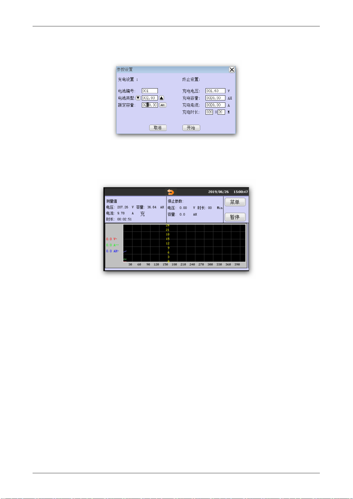
●Charge, discharge, activation and curve indication functions:
The Tester will record the battery voltage and current curve trends during charging, discharging and activation. The
curve can be displayed after test. The right side of the screen shows the charge (discharge) curve, and the left side
shows the charge (discharge) or activation parameters, including: voltage (current) indicating, charge (discharge)
current, charge (discharge) cutoff voltage, test duration.
●Data Review
During the charging (discharging) or activating operation, after test interrupted for some reason, you can choose
whether to view the data. While viewing the data, press the left or right button to view related data and curve
trends.
●Data Management
This feature allows the user to manage the battery's measured data, including data uploads and curve playback.
●System Upgrade
This feature allows users to perform online software upgrades.
1.3 Characteristics
Using the latest online programmable CPU, users can use the microcomputer to update the instrument
software to continuously improve the performance of the instrument.
Modular structure, reasonable design and reliable operation.
Comprehensive measurement and accurate display of battery voltage, current, charge (discharge) and
activation results and waveforms.
Powerful, it can charge (discharge) the battery separately, and charge and discharge continuously for several
times (not more than 99 times).
English menu operation, easy to learn and use.
The data stored in Tester can be transferred to computer and managed by the PC software.
The PC data management software can analyze the data of battery charge (discharge) and activation, and

DFT-6900 Battery Activator Instruction Manual
4
generate corresponding data reports.
1.4 Working Principle
The working principle of the Tester is to control the single-chip microcomputer by operating the keyboard, and LCD
displays the operation menu and test control results.
The Tester provide charge/Discharge and monitoring function, also user can save one set of curve for each battery
charge, separate discharge and battery activation, which greatly improves the user's use efficiency. The Tester USB
interface allows users to communicate with the computer via a U-disk. By transmitting the data to the PC, the battery
quality can be monitored for a long time. Through the analysis of the battery operating status data, various problems
which affect the battery quality can be found.
1.5 Technical Specifications
Technical Specifications
Measurement Mode
Resolution
Accuracy
Charge Current
1-100A (cell: 2V)
1-30A (cell: 12V)
1-30A(cell:6V)
0.1A
1A
Discharge Current
1-100A(cell:2V) 1-30A(cell:12V )
1-30A(cell:6V)
0.1A
1A
Charge Voltage
1.7-2.4V(2V)
5.4-7.2V(6V)
10.2-15V(12V)
0.1V
0.25%
Discharge Voltage
1.7-2.4V(2V)
5.4-7.2V(6V)
10.2-15V(12V)
0.1V
0.25%
Power Supply
AC 220V±10%
LCD Display
5 inch colorful touch screen
Operating Temperature
5℃~50℃
Operating Humidity
5%~90%RH
Dimension
40x30x20cm
Net Weight
10Kg
Communication Port
USB

DFT-6900 Battery Activator Instruction Manual
5
1.6 Main Parts
The main unit comes with two current clamps (one red and one black) and one voltage detection line. Connect the
three-pin terminal of the voltage detection line to the “voltage detection” terminal on the back panel of the main unit.
The terminals of the red current clamp are connected to the red terminal block on the back panel, and the terminals of
the black current clamp are connected to the black terminal block on the back panel. Note: It is strictly forbidden to
reverse connection!
1.7 Operation Instruction
Touch screen for all operation
1.8 Wiring
Activation, charge/discharge wiring: Connect the current/voltage clamps with the battery positive/negative
poles: Black clamp to negative pole, red clamp to the positive pole. (Note: the positive and negative poles are
strictly prohibited to be reversed connection). If the current clamp is reversed, it will cause serious damage to the
instrument. If the voltage clamp is reversed connection, the instrument cannot be operated normally, at the same
time, the instrument will prompt the user to convert the (voltage) clamps, but it will not cause damage to the
instrument.
Current clamp reversed connection not allowed to battery poles; otherwise the instrument
will be seriously damaged.

DFT-6900 Battery Activator Instruction Manual
6
Chapter 2 Functions & operations
Power On
Turn on the power switch on the back of the Tester, LCD displaying the model and version No. Wait a moment to
automatically enter the main interface. The main interface is as follows:
2.1 Discharge
Click “Discharge “to enter parameters setting
It is necessary to set six parameters: battery number, battery type, rated capacity, cutoff voltage, discharge current,
and discharge duration. Set the discharge parameters and press the [Start] key to enter the discharging status
indication interface. Press the [Back] icon to return to the main menu.
Discharging tested data displayed: the battery voltage, the discharge current, the discharged capacity, the
discharged time, and the stop parameters

DFT-6900 Battery Activator Instruction Manual
7
2.2 Charge
Click “Charge” to enter parameters setting interface.
It is necessary to set six parameters: battery number, battery type, rated capacity, cutoff voltage, charge current,
and charge duration. Set the discharge parameters and press the [Start] key to enter the charging status indication
interface. Press the [Back] icon to return to the main menu.
Charging tested data displayed: the battery voltage, the charge current, the charged capacity, the charged time, and
the stop parameters
Note:
1. The cut-off voltage set in the parameter setting is to prevent the battery from over
charging/discharging which leads to battery damaged. Cutoff value examples: 2V
battery—discharge cutoff voltage: 1.85V, charge cutoff voltage: 2.40V. 6V battery--discharge cutoff
voltage: 5.40V, charge cutoff voltage: 7.20V. 12V battery-- discharge cutoff voltage: 10.8V, charge
cut-off voltage: 14.50V
2. For small-capacity batteries, you should also pay attention to the setting of charge/discharge
current. It is recommended to charge/discharge at a rate of 0.1 C (i.e., the charge/discharge current
is 0.1 times the battery capacity value).

DFT-6900 Battery Activator Instruction Manual
8
2.3 Activator
Click “Activator” to enter parameters setting interface
2.3.1Activator Setting Interface
In the activation setting interface, the battery number, battery type, rated capacity, discharge voltage limit, charge
limit voltage, and number of cycles (the number of times is not more than 10) are displayed. As shown below:
Enter the battery activation interface. As with the charge/discharge function settings, the battery type must be
selected before the activation parameter setting is performed: 2V battery / 6V battery / 12V battery. The activation
settings interface is as follows:
After clicking the up and down direction keys to set the "Cycle No.", you can set the parameters of each
activation by clicking the page up and page down. The setting parameters: cutoff voltage, current, capacity and
duration.
2.3.2Activating Process
The activating process includes discharging & charging (please refer to “Discharge” & “Charge”): press the [Back]
key to interrupt the activation.
2.4 Data Management
Test results can be viewed, exported, deleted, and formatting in the Data Management menu. Data
management includes discharge measurement data, charge measurement data, and activation measurement data.
2.4.1 Data Review
In the main menu, enter “Data Management”, select the data type, select the data, and press the [View] key to

DFT-6900 Battery Activator Instruction Manual
9
display the measurement result.
View Data
Discharge Data
Activating Data
2.4.2 Data Transfer
In the data management menu, click the [U-disk], the data will be transferred. Please insert the U-disk first, and
the green "U" symbol will be displayed in the upper right corner of the menu.
Note: U-disk read and writes error
1. U-disk plugged in properly.
2. It is strongly recommended that users use the newly formatted (that is, empty) U-disk for reading and writing
operations, because the U-disk with lots of files will affect the correctness of reading and writing. If the U-disk is
wrong, please reformat the U-disk and try again.

DFT-6900 Battery Activator Instruction Manual
10
3. When performing the operation, please insert the U-disk first, and wait until the indicator light of the “U-disk”
is no longer flashing before other operations.
4. Do not plug or unplug the U-disk while the U-disk is reading or written.
5. After the U-disk is finished reading/writing, please wait until the “U-disk” indicator light is no longer flashing
before plugging and unplugging the U-disk.
6. If there is an error in the process of reading and writing the U-disk or no response for a long time, please use
FAT to format the U-disk and try again.
2.4.3 Data Delete
In the data management menu, select the data and click [Delete] option to delete the selected data.
2.4.4 Data Formatting
In the data management menu, click the [Format] option to delete all data.
2.5 System setting
In the main menu interface, click "System Settings" to enter the system management interface, which includes
language selection, time setting, update software. The interface is as follows:
2.5.1 Time Setting
All test data time is recorded & displayed by the instrument clock. Therefore, it is recommended to adjust the
clock to real local time before using the instrument. Adjust the clock path: “Main Interface” → “System Settings”
→ “Clock Settings”. The clock setting interface is as shown in the figure: After setting the time, click the “Save”
button to update to the required time.
2.5.2 System Upgrade
The instrument software could be updated by U-disk. First, put the upgraded software image file into the U-disk,
insert to Tester USB port, enter the “System Settings” menu page, and click the “Update Program” menu item.

DFT-6900 Battery Activator Instruction Manual
11
The figure shows below:
Click the [Update] button to enter the software update program. The meter automatically restarts and loads the
update file of the U-disk to Tester. After the software update is completed, the Tester enters the boot interface and
can perform normal operation
2.5.3 Language
Enter the "System Settings" menu page; click the "Language Settings" menu, the figure shows below:
2.5.4 Version Details
Click the “System Information” on the main menu page to view the instrument system software version, as shown
in the figure:
Click “OK” to exit

DFT-6900 Battery Activator Instruction Manual
12
Chapter 3 Daily Maintenance
3.1 Clean &Maintenance
3.1.1 Mani Unit Maintenance/Clean
Clean the main unit and its accessories with damp cloth and a mild soap. Do not use abrasives, solvents, or
alcohol, as they can deform or discolor the Tester and the accessories.
3.1.2 Clamps Maintenance/Clean
Clean the main unit and its accessories with damp cloth and a mild soap.
3.2 Storage
After using Tester, put the main unit and all its accessories into the carrying case, store the case in ventilating place
under proper temperature and humidity. Never expose the Tester and its accessories to water, high humidity, or
dampness.

DFT-6900 Battery Activator Instruction Manual
13
Chapter 4 FAQ
Do not start up
Check power supply wiring
No signals after the Tester is on
The Tester may not be properly connected. If so, make sure it is well connected.
Activator for N times charge/discharge alone
Since the duration of charge and discharge alone should not exceed 18 hours, if it is required to charge and
discharge for more than 18 hours, use N cycles to prolong the time. Example: If the charging required time is 28
hours, set the activation cycle: 2, the first charging time is 18 hours, the discharge duration is 0, the second
charging time is 10 hours, and the discharge duration is 0. The long time discharge method is the same as above,
and the charging time should be 0.
Battery No. Setting
There are 4 digits for battery number. In order to facilitate management, the first two digits are for battery group
number, the last two digits are for the battery number, and there are up to 99 Strings, and the maximum number of
batteries in the same group is 99.

DFT-6900 Battery Activator Instruction Manual
14
The U-disk cannot be detected after it is inserted to the PC
The U-disk may not be well inserted. If so, reinsert it correctly.
The U-disk may not be in FAT format. If so, format the U-disk.
And if other problems occurred, contact your dealer or our representatives.
Table of contents
Other THOMSON Camera Accessories manuals

THOMSON
THOMSON LDK 5310 User manual

THOMSON
THOMSON 510055 User manual

THOMSON
THOMSON LDK 5302/60 User manual

THOMSON
THOMSON LDK 4019 LDK 4019 User manual

THOMSON
THOMSON LDK 5411 User manual

THOMSON
THOMSON grass valley LDK 5305 User manual

THOMSON
THOMSON LDK 5301 User manual

THOMSON
THOMSON LDK 200 User manual

THOMSON
THOMSON LDK 4020 User manual

THOMSON
THOMSON LDK 4021 User manual