THOMSON LDK 5310 User manual

LDK 5310LDK 5310
LDK 5310LDK 5310
LDK 5310
5-inch SDTV Viewfinder
User’s Guide
3922 496 48541 St.01

Für diese Unterlage behalten wir uns
alle Rechte vor (Gemäß DIN 34).
Technische Änderungen im Zuge der
Weiterentwicklung vorbehalten.
Copyright
FCC Class A Statement
Declaration of Conformity
Copying of this document and giving
it to others, and the use or com-
munication of the contents thereof,
are forbidden without express au-
thority. Offenders are liable to the
payment of damages. All rights are
reserved in the event of the grant of
a patent or the registration of a utility
model or design. Liable to technical
alterations in the course of further
development.
Toute communication ou reproduc-
tion de ce document, toute ex-
ploitation ou communication de son
contenu sont interdites, sauf au-
torisation expresse. Tout man-
quement à cette règle est illicite et
expose son auteur au versement de
dommages et intérêts. Tous nos
droits sont réservés pour le cas de la
délivrance d'un modèle d'utilité. Sous
réserve de modification au cours de
l'évolution technique.
© Thomson Multimedia Broadcast Solutions 2002
We, Thomson Broadcast Solutions Nederland B.V., Kapittelweg 10, 4827 HG Breda, The Netherlands declare under
our sole responsibility that this product is in compliance with the following standards:
EN60065
EN55103-1
EN55103-2
following the provisions of:
a. the Safety Directives 73/23//EEC and 93/68/EEC
b. the EMC Directives 89/336/EEC and 93/68/EEC
: Safety
: EMC (Emission)
: EMC (Immunity)
This product generates, uses, and can radiate radio frequency energy and if not installed and used in accordance with
the instructions, may cause interference to radio communications.
It has been tested and found to comply with the limits for a class A computing device pursuant to Subpart J of part 15
of FCC rules, which are designed to provide reasonable protection against such interference when operated in a com-
mercial environment.
Operation of this product in a residential area is likely to cause interference in which case the user at his own expense
will be required to take whatever measures may be required to correct the interference.

02.35.4 User's Guide LDK 5310/00 - 5-inch SDTV Viewfinder 1-1
LDK 5310/00
5-inch SDTV Viewfinder
User's Guide
Contents
Safety Instructions ............................................ 1-2
About This Manual ............................................. 1-4
OperatingInstructions........................................ 1-5
Connections....................................................... 1-7
Specifications .................................................... 1-7
Electrical Drawings .......................................... 2-1
On Air Board ...................................................... 2-2
Video Pre Amp /IIC Interface Board .................. 2-4
SMPSDC-DC Converter Board ......................... 2-8
CRTBoard ....................................................... 2-12
DeflectionBoard .............................................. 2-14
Mechanical Exploded Views ............................ 3-1
Mech. 5-inch Viewfinder short............................ 3-2
VF-Bracket-ASSY ............................................. 3-3
5-inchViewfinder ............................................... 3-4
Parts Lists ........................................................ 4-1

1-2 User's Guide LDK 5310/00 - 5-inch SDTV Viewfinder 02.35.4
Safety Instructions
Safety Summary
This informaton is intended as a guide for trained and
qualified personnel who are aware of the dangers
involved in handling potentially hazardous electrical/
electronic equipment. It is not intended to contain a
completelist of allsafety precautionswhich should be
observedby personnelin usingthis orother electronic
equipment.
The installation, maintenance and service of this
equipment involves risks both to personnel and
equipment and must be performed only by qualified
personnel exercising due care.
Personnel engaged in the installation, operation,
maintenanceor servicing ofthis equipment areurged
tobecome familiar withFirst Aid theoryand practises.
During installation and operation of this equipment,
local building safety and fire protection standards
must be observed.
Beforeconnecting the equipmentto thepower supply
of the installation, the proper functioning of the
protective earth lead of the installation needs to be
verified.
Whenever it is likely that safe operation is impaired,
theapparatus mustbe made inoperativeand secured
against any unintended operation. The appropriate
servicing authority must then be informed. For
example,safety islikelyto beimpaired iftheapparatus
fails to perform the intended function or shows visible
damage.
Thisproduct hasbeen designedand testedaccording
to EN60065.
Cautions and Warnings
Whenperforming service, besure toread and comply
withthe warning and cautionnotices appearing in the
manuals. Warnings indicate danger that requires
correct procedures or practices to prevent death or
injury to personnel. Cautions indicate procedures or
practices that should be followed to prevent damage
or destruction to equipment or property.
WARNING
THE CURRENT AND VOLTAGES PRESENT IN THIS
EQUIPMENT ARE DANGEROUS. ALL PERSONNEL
MUST AT ALL TIMES FOLLOW THE SAFETY
REGULATIONS.
ALWAYS DISCONNECT POWER BEFORE REMOVING
COVERS OR PANELS.
ALWAYS DISCHARGE HIGH VOLTAGE POINTS
BEFORE SERVICING.
NEVER MAKE INTERNAL ADJUSTMENTS, PERFORM
MAINTENANCE OR SERVICE WHEN ALONE OR WHEN
FATIGUED.
IN CASE OF AN EMERGENCY ENSURE THAT THE
POWER IS DISCONNECTED.
ANY INTERRUPTION OF THE PROTECTION
CONDUCTOR INSIDE OR OUTSIDE THE APPARATUS,
OR DISCONNECTION OF THE PROTECTIVE EARTH
TERMINAL, IS LIKELY TO MAKE THE APPARATUS
DANGEROUS. INTENTIONAL INTERRUPTION IS
PROHIBITED.
FOR SAFETY REASONS THE CPU MUST BE MOUNTED
IN A 19-inch RACK WHICH HAS SAFETY COVERS
ACCORDING TO IEC65.
WHEN TWO CPUs ARE MOUNTED ABOVE EACH
OTHER THE MINIMUM DISTANCE BETWEEN THEM
MUST BE 50MM OR THE RACK MUST BE FORCE-AIR
COOLED.
USE ONLY FUSES OF THE TYPE AND RATING
SPECIFIED.
CAUTION
To prevent risk of overheating, ventilate the
product correctly.
Connect the product only to a power source with
the specified voltage rating.
Only connect a Triax cable from the LDK 6
camera family to an LDK 6 CPU. Never connect it
to any other base station.
Never connect the Triax cable from a camera to a
CPU of a different family; never connect the LDK
family to the TTV family.
Do not allow system ground currents to exceed
1.5A in the outer shield of the triax cable or 0.2A
in other cable shields.
It is strickly prohibited to short circuit the inner
and outer shields of a triax cable used to connect
a camera to a base station.

02.35.4 User's Guide LDK 5310/00 - 5-inch SDTV Viewfinder 1-3
Symbol Colour Explanation
Red Highvoltage terminalat which
a voltage, with respect to an
other terminal, exists or may
beadjusted to 1000V or more.
Yellow/Black Live part.
Yellow/Black Thismarkingindicates thatthe
operator must refer to an
explanation in the Instruction
Manual, or that a specific
component must be replaced
by the component specified in
the documentation for safety
reasons.
White/Black Protective earth (ground)
terminal.
Cathode ray tubes
Components marked on the circuit diagram are
criticalfor safetyandinclude thosespecified tocomply
withX-ray emission standardsfor unitsusing cathode
ray tubes and those specified for compliance with
various regulations regarding spurious radiation
emission.
When servicing units that use cathode ray tubes
(CRTs), the cathode ray tubes themselves, the high
voltage circuits and related circuits are specifically
chosen so that they comply with recognized codes
pertaining to X-ray emission.
Consequently, when servicing, replace the cathode
ray tubes and other parts with specified parts only. Do
notattempttomodifythesecircuitsasanyunauthorized
modification can increase the high voltage value and
cause X-ray emission from the cathode ray tube.
Handle the cathode ray tube only when wearing
shatterproof goggles and after discharging the high
voltage completely.
Earthing
The rear of a CPU has two separate screw terminals
for protective earth (PE) and video earth (VE).
These are normally connected by a metal strap. The
protectiveearth terminalis internally connectedto the
protective earth conductor of the power cable. If
required,thecentral earthconnectionwireof thestudio
can be connected to terminal PE.
In normal circumstances the connection between the
protective earth and the video earth should not be
broken.
The metal strap may be removed only if the studio (or
OB van) is equipped with separate protective and
video earth systems. Under these circumstances the
video earth terminal must be connected to the central
functional earth potential (video earth) of the studio.
This earth potential should have functional protective
and noiseless earth (FPE) qualities as stated in the
VDE regulation 0800/part2. A low impedance
interconnection of both earth conductors must be
provided at the central studio earthing point.
WARNING
THE UNIT MUST ALWAYS BE CONNECTED TO
PROTECTIVE EARTH.
Mains Lead Wiring for UK Users
Thewiresin themainsleadare colouredinaccordance
with the following code:
GREEN AND YELLOW - EARTH
BLUE - NEUTRAL
BROWN - LIVE
As the colours of the wires in the mains lead of this
apparatus may not correspond with the coloured
markingsidentifyingthe terminalsinyour plugproceed
as follows:
• The wire coloured GREEN AND YELLOW must be
connected to the terminal on the plug marked with
the letter E or by the safety earth symbol or
coloured GREEN or GREEN AND YELLOW.
• ThewirecolouredBROWN mustbeconnectedtothe
terminal marked with the letter L or coloured RED.
• The wire coloured BLUE must be connected to the
terminalmarkedwith theletterNor colouredBLACK.
Ensure that your equipment is connected correctly - if
you are in any doubt consult a qualified electrician.
VE
PE
Metal
strap

1-4 User's Guide LDK 5310/00 - 5-inch SDTV Viewfinder 02.35.4
About This Manual
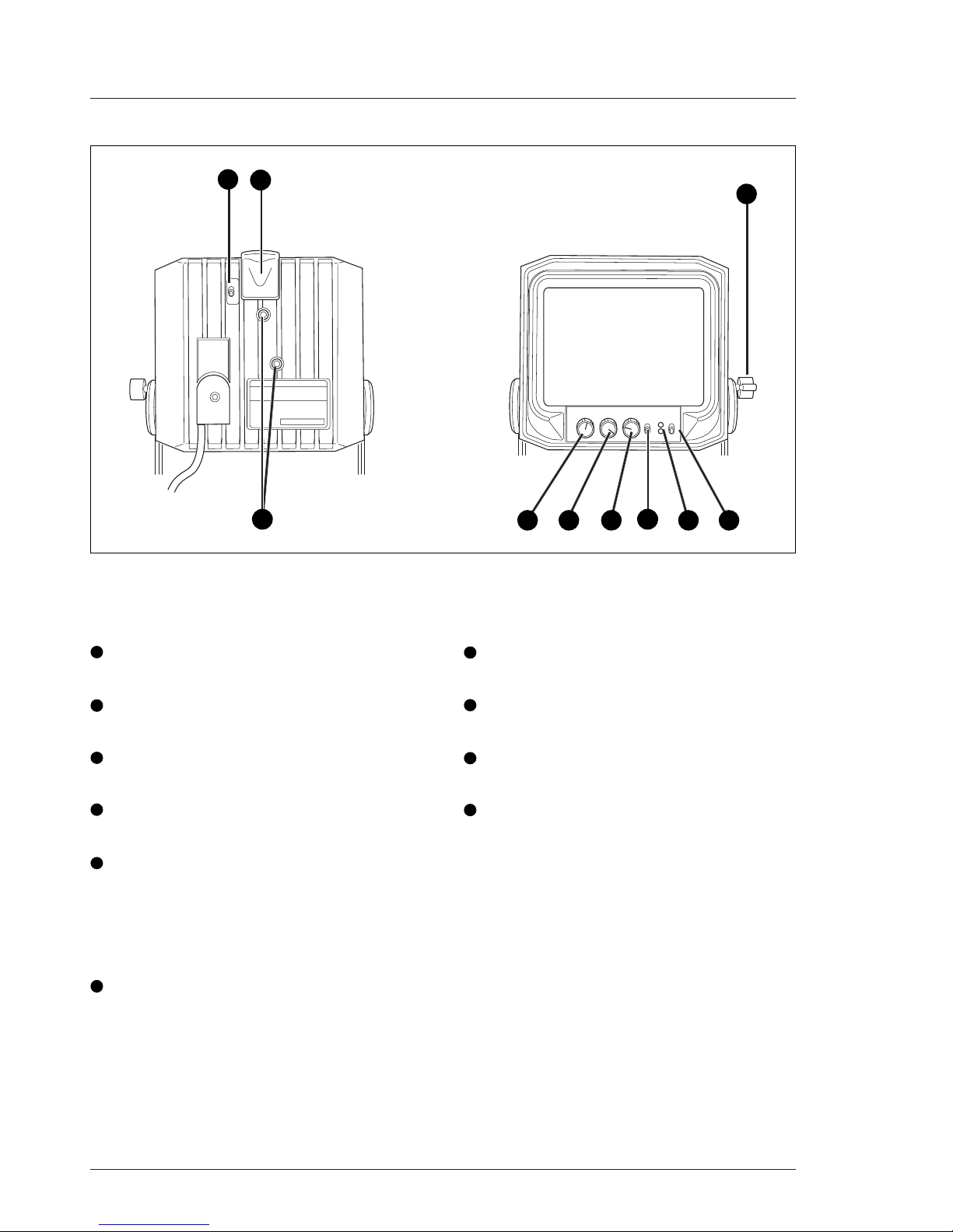
Purpose of this manual
The purpose of this manual is to present a global
description of how to operate the viewfinder. Consult
the Operator's manual of your camera as required
during and after the installation process.
This manual is an integral part of the service policy.
Itensures thatyouwill beable toinstall yourviewfinder
to meet the requirements of your environment. The
manual provides first line service information so that
suitably qualified service personnel can detect and
repair faults, normally by module replacement.
Becauseofthe complexityofsome ofthecomponents,
second line service can only be carried out at the
specially equipped service centres and information
concerningsecond linemaintenanceis notsupplied in
this manual.
Intended audience
The manual is intended as a guide to those with a
workingknowledgeofcamera systemsandinstallation
techniques.The first linedetection andrepair of faults
requiresageneralknowledgeoftestand measurement
techniques. The guide is so designed that it can be
used as wel to the viewfinder, as wel a simple
proceduralguide to those whowish to setup andstart
shooting immediately, and as a reference work to be
consulted as required during the long life of the
viewfinder.
Service policy
TheLDK5310 isa sophisticatedviewfinder containing
state-of-the-art electronic components which are
designed to provide long-life operation without the
need for maintenance. With this in mind, the service
policy of Thomson Multimedia Broadcast Solutions
endeavoursto ensurethat helpwill bequickly onhand
in the unlikely event of anything going wrong. The
guiding principles of the Thomson Multimedia
BroadcastSolutions firstlinemaintenance philosophy
are speed and cost effectiveness. First line
maintenance is dedicated to keeping your viewfinder
operational, despite a fault, by replacement boards
andthe replacementof minor mechanicalparts bythe
user.
CAUTION
Without additional protection the LDK5310 is
protected according to safety specification
EN60529 up to level IPX3 (spraying water).
Exposure to splashing or jetting water can
result in harmful effects.
Packing/Unpacking
Inspecttheshipping containerfor evidenceofdamage
immediately after receipt. If the shipping container or
cushioning material is damaged, it should be kept
untilthe contents ofthe shipment have beenchecked
for completeness and the units have been checked
mechanically and electrically.
The contents of the shipment should be checked
againstthe packinglist. Ifthecontents areincomplete,
if there is mechanical damage or defect, or if the units
do not perform correctly when unpacked, notify your
Thomson Multimedia Broadcast Solutions sales or
service centre within eight days. If the shipping
containershows signs of damageor stress, notify the
carrier as well.
If a unit is being returned to Thomson Multimedia
Broadcast Solutions for servicing, try to use the
containers and materials of the original packaging.
Attach a tag indicating the type of service required,
returnaddress, model number,full serial numberand
the return number which will be supplied by your
Thomson Multimedia Broadcast Solutions service
centre.
If the original packing can no longer be used, the
following general instructions should be used for
repacking with commercially available materials:
a. Wrap unit in heavy paper or plastic.
b. Use strong shipping container.
c. Usea layerof shock-absorbing materialaround all
sides of the unit to provide firm cushioning and
prevent movement inside container.
d. Seal shipping container securely.
e. MarkshippingcontainerFRAGILEto ensurecareful
handling.

02.35.4 User's Guide LDK 5310/00 - 5-inch SDTV Viewfinder 1-5
Operating Instructions
The5 inchviewfinder LDK5310/00 is intendedfor use
with LDK100 series cameras.
Attaching the 5" viewfinder to the camera
Caution
Before connecting, make sure that the camera is
switched off.
a. Slide the top mount into the slot on the camera,
until you hear it click into place.
b. Connect the viewfinder cable to the viewfinder
connector on the camera.
c. Fasten the cable with the two cable clamps on the
camera.
Torelease theviewfinderpush therelease leverinand
slide the viewfinder out of the slot.
Adjusting the 5" viewfinder position
You can rotate the viewfinder freely.
To tilt the viewfinder:
a. Loosen the tilt locking knob by turning it
counterclockwise.
b. Tilt the viewfinder to the desired position.
c. Securethe tilt lockingknob by turningit clockwise.

1-6 User's Guide LDK 5310/00 - 5-inch SDTV Viewfinder 02.35.4
ON
DIM
OFF
Brightness Contrast Peaking Optional Power
Onair
Iso
Mom
On
On
Off
Location of Controls and Functions
1Front on-air indicator switch
Switches the front on-air indicator on and off.
2Front on-air indicator
Lights to indicate that the camera is on air.
3Tilt locking knob
Locks the tilting mechanism of the viewfinder.
4Power switch
Switches the viewfinder on and off.
5On-airindicator
Lights to indicate that the camera is on air.
ISOindicator
Lights to indicate that the camera is selected
and ready to be switched on-air.
6Optionalswitch
This switch is mounted on the viewfinder to
allow future features to be incorporated.
7Peaking control
Adjusts the peaking (crisp) on and off.
8Contrast control
Adjusts the contrast of the viewfinder display.
9Brightness control
Adjuststhebrightness ofthe viewfinderdisplay.
10 Camera number attachment slots
Attach a camera number to these slots.
123
45
6
789
10

02.35.4 User's Guide LDK 5310/00 - 5-inch SDTV Viewfinder 1-7
Connections Specifications
Dimensions
Length x width x height: 255 x 126 x 135
(withoutsunhood)
Weight approx. 3.1 kg including tilt mechanism
Systems
625 lines, 50 Hz, CCIR/PAL
525 lines. 60 Hz, EIA/NTSC
automatic control of vertical picture amplitude,
automatic aspect ratio control 16:9 and 4:3,
PowerSupply
-50 Vdc to -100 Vdc
or
+10.5 to 17 Vdc (automatically selected if -80V
notavailable)
PowerConsumption
Max: 12 W at -80 Vdc
Max: 10 W at +10.5 to 17 Vdc
CRT
5" CRT High Resolution type
Linearityand geometry
Distorsion: 1% within a circle with a diameter of
picture height, rest 1.5%
Resolution(horizontal)
Min. 650 lines in centre of screen at 400 cd/m2
Frequencyresponse
5 MHz within -1 dB to +2 dB with resp. to
0.1 MHz
10 MHz - 3 dB
Peaking
0-12dB at approx. 3.5MHz
Black level stability
Change of black level 1.5% with respect to
white level
Environmentalconditions:
Operatingtemp.: -20 to +45 °C
Non-operatingtemp.: -25 to +70 °C
Operatinghumidity: 93%
ViewfinderConnector, frontview
Hirose 20-pin female, shielded cable
1
6
5
10
11 15
20
16
1. -80V
2. n.c.
3. GND
4. INTN-D
5. n.c.
6. n.c.
7. vf video ret
8. SDA-D
9. SCL-D
10. n.c.
11. GND
12. vf video
13. n.c.
14. n.c.
15. GND
16. +batt
17. +batt
18. n.c.
19. n.c.
20. shield
Note: shield cable to pin marked shield

1-8 User's Guide LDK 5310/00 - 5-inch SDTV Viewfinder 02.35.4

Electrical Drawings User's Guide LDK 5310/00 - 5-inch SDTV Viewfinder 2-1
Section 2
Electrical Drawings
On Air Board ...................................................... 2-2
Video Pre Amp /IIC Interface Board ................... 2-4
SMPSDC-DC ConverterBoard .......................... 2-8
Contents
CRTBoard ....................................................... 2-12
DeflectionBoard .............................................. 2-14

2-2 User's Guide LDK 5310/00 - 5-inch SDTV Viewfinder Electrical Drawings
On Air Board
Assembly
1 110-1
3922 450 04501
24-03-1999
PCB 701321-1

Electrical Drawings User's Guide LDK 5310/00 - 5-inch SDTV Viewfinder 2-3
On Air Board
Circuit diagram
1 130-1
3922 450 04501
24-03-1999
PCB 701321-1

2-4 User's Guide LDK 5310/00 - 5-inch SDTV Viewfinder Electrical Drawings
12-12-1997
2110-1
T van 't Hooft
3922 450 05121
VIDEO PRE AMP /IIC INTERFACE BOARD
Assembly drawing

Electrical Drawings User's Guide LDK 5310/00 - 5-inch SDTV Viewfinder 2-5

2-6 User's Guide LDK 5310/00 - 5-inch SDTV Viewfinder Electrical Drawings
12-12-1997
2130-1
T van 't Hooft
3922 450 05121
VIDEO PRE AMP /IIC INTERFACE BOARD
Circuit Diagram

Electrical Drawings User's Guide LDK 5310/00 - 5-inch SDTV Viewfinder 2-7
12-12-1997
2130-2
T van 't Hooft
3922 450 05121
VIDEO PRE AMP /IIC INTERFACE BOARD
Circuit Diagram

2-8 User's Guide LDK 5310/00 - 5-inch SDTV Viewfinder Electrical Drawings
17-11-1998
2110-1
T van 't Hooft
3922 450 05101
SMPS / DC-DC CONVERTER BOARD
Assembly drawing

Electrical Drawings User's Guide LDK 5310/00 - 5-inch SDTV Viewfinder 2-9
17-11-1998
2110-2
T van 't Hooft
3922 450 05101
SMPS / DC-DC CONVERTER BOARD
Assembly drawing

2-10 User's Guide LDK 5310/00 - 5-inch SDTV Viewfinder Electrical Drawings
17-11-1998
2130-1
T van 't Hooft
3922 450 05101
SMPS / DC-DC CONVERTER BOARD
Circuit diagram
SMPS
Table of contents
Other THOMSON Camera Accessories manuals

THOMSON
THOMSON LDK 4019 LDK 4019 User manual

THOMSON
THOMSON LDK 4020 User manual

THOMSON
THOMSON LDK 4021 User manual

THOMSON
THOMSON LDK 200 User manual

THOMSON
THOMSON LDK 100 User manual

THOMSON
THOMSON 510055 User manual

THOMSON
THOMSON LDK 5301 User manual

THOMSON
THOMSON 512501 User manual

THOMSON
THOMSON LDK 5411 User manual

THOMSON
THOMSON grass valley LDK 5305 User manual