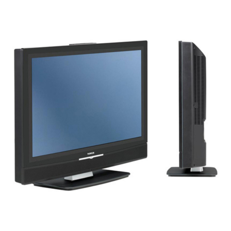
THOMSON CM 36512 VI User manual

THOMSON
0
_____
A sight
for
sore
eyes:
M
____________
_

Contents
pages
I-INTRODUCTION
•. ••. . ••. ••••••••. . •. . . . . . . . . . . .. .. . .. ••. •. . .. . .. . .. .. •. .. .. ••.. .. •. . .. . 4
11-
SAFETY PRECAUTIONS •. •••••••••••. .••••. . . . .. •. •. .•••. •. . . .. . . .. •.. •.••.. •. . .. . . . • ... 4
111-
LOCATION
OF
CONTROLS
••••.••••••..••••.•.....•..••••.......•......•.••..•....•••...
4
IV
-CONNECTING THE MONITOR TO THE COMPUTER. . .. •. . ••. .. .
..
. . . •. ••. •. •. •.. . .. .. . •.
..
. 5
V - RECOMMENDATION. . ••. . •••••. •.••. . •. •. •. . . ••. .. •. . .. . . . . . .. . .. . .•.••. .•. .. . . .. . ••.
..
7
VI-
ADJUSTMENTOF DISPLAY. . . ••. .. . . . . . . .. . . . . . . . .. . .. . . . •. . •. .. . .. . .. . . .. .. . . . .. .. . •.
.•
7
VII-SPECIFICATIONS
••..
•. •. . . . . •.. . ••••. . . . •••••. . •••.. •••. . . . .. . . •••. . .. . . ••.. ••. .. . ••.
..
8
VIII-
CONNECTOR. . . . . .. . . . •. . . . .
..
. . . .. . . . . . . . . . .. . .. . . .. . . . . .. . . . .. . . .. . . . ... .. . . .. . . . • .
..
8

FIGURE 1
FRONT
VIEW
BACK
VIEW L I I J
\\\\\\1111/11
Power Cord
-3-

I - INTRODUCTION
Congratulations on your purchase
of
theTHOMSON
CM
36512
VI
color monitorl Your THOMSON
CM
36512 VI color monitor
will provideyou withahighquality,reliabledisplaywhichwill add
to
yourcomputingcomfortforyears
to
come.Thisdisplaymonitor
is a precision engineered productc!esigned
for
use withthecom-
puter
system
which
delivers a
RGB
Plus intensity signal in
TTL level
or
a composite video
or
a separate chroma/Luma
video signal.
Like all modern precision instruments, this monitorrequires pro-
per installation and care. It has manyfacilities
to
offerand forthe
best understanding
of
these facilities please read the operating
instructions thoroughly before installing
or
using this monitor.
II -SAFETY PRECAUTIONS
The following safety instructions have been included
in
compli-
ancewith safetystandard regulations.
Please
read
themcarefully.
1 - Read
instructions
-All the safety and operating instruc-
tions should be
read
before the monitoris operated.
2 - Retain
instructions
-Thesafetyand operating instructions
should be retained for future reference.
3 - Heed
warnings
-All warnings
on
the monitor and
in
the
operating instructions should
be
adhered to.
4 -
Follow
instructions
-All operating and use instructions
should
be
followed.
5 -
Water
and
Moisture
-The monitorshould not
be
used near
water
or
exposed
to
excessive moisture
to
reduce therisk
of
electric shock
or
fire.
6 -
Ventilation
-The monitor should be situated
so
that its
location
or
positiondoesnotinterferewithitsproperventila-
tion. Neverblock
or
coverventilation openingswith cloth
or
othermaterial.Themonitorshouldnot
be
placed
in
abuilt-in
installation, such
as
acabinet
or
bookcase,thatmay impede
the
flow
of
airthrough the ventilation openings.
7 -
Heat
-The monitor s!:lould
be
situated away from heat
source such
as
radiators, heat registers, orotherelectronic/
electrical applianceswhich produceheat.Avoidexposureto
direct sunlight.
8 -
Power
Sources -The monitor should
be
connected to
an
AlCpowersupplyonly. Itshould never be connected
to
D/C
or
power
off
any
other
voltage
or
frequency than ;
10-
120V,
60
Hz.
9 - Grounding-The monitorshouldalways
be
plugged into
an
outlet that provides grounding (that is a 3-prong plug
outlet).
10
-
Power
Cord
Protection
-Power supply cords should
be
routed
so
thattheyare not likely
to
be
walkedon orpinched
by items placed upon
or
againstthem.
Pay
particularatten-
tion
to
cords at plugs, convenience receptacles, and the
point at which
it
exits from the appliance,
11
-Cleaning -Tht) monitorcabinetshould becleaned onlywith
asoftdrycloth.The
CRT
glass
can
be
cleaned bywipingwith
asoft drycloth that has
been
dampened with
wateror
glass
cleaner.
Do
NOTspray water
or
glass cleanerfluids directly
onto the
CRT.
12
-Non-Use
Periods-
Thepowercordofthe
monitor
shouldbe
un~lugged
fromtheoutletwhen leftunusedforalongperiod
of
time.
13
-
Object
and Liquid Entry -
Care
should
be
taken so that
objects do not fall and liquids are not spilled into the enclo-
sure through openings.
14
-DamageRequiring
SeN
ice
-The monitorshouId
be
servi-
ced by qualified personnel when:
A.
The powersupplycord orthe plug has
been
damaged,or,
B.
Objects havefallen,orliquid
has
been
spilled intothe
mo-
nitor, or,
C.
The monitor
has
been
exposed to rain orexcessive mois-
ture, or
D.
The monitordoes not appeartooperate normallyorexhi-
bits a marked change
in
performance, or,
E.
The monitor has
been
dropped, or the enclosure
damaged.
15
-
SeNicing
-
The
usershould notattemptto service
the
moni-
tor beyond that described
in
the operating instructions. All
otherservice should
be
referred toqualified service personnel.
III -LOCATION OF CONTROLS
(refer
to
Figure
1,
page 3)
1
-Power
Indicator
2
-Power
Switch
3
-Door
4
-Input
Signal/Text Switch
Position 1 - NTSC (Separate CHROMA/LUMA) mode
2
~
Display
RGBI
green screen color
3 - Display
RGBI
16
full color capability
4 - Video composite (NTSC) mode
5
-Horizontal
Picture
Shift
(CO)
6
-Vertical
Synchronization
(CD)
7
-Vertical
Picture
Amplitude
(m)
8
-Intensity/Color
Control
(.
(!)
)
9
-Tint
Control
10
-Brightness.
({)
)
. 11
-Contrast
«()
12
-Volume
(....::J)
-4-
13
-"Sound"
Input
Connector RCA Phonojack
14
:-9
pin
'0'
Sub. Miniature Connector
15
-UVideo
or
"Luma"
Input
Connector
RCA
Phonojack
16
-Focus
17
-"CHROMA"
input
connector
RCA
Phonojack

IV
-CONNECTING THE MONITOR
TO
THE COMPUTER
As mentioned earlier your monitor has the capability
to
be used
with
personal computers
that
feature .either a video composite
or
a separate Chroma/Luma
output
(NTSC)
or
RGBI
TTL
out-
put.Before
attempting
to
connect
the
monitorto
your
comput-
er
consult
your
computer,.user's manual and determine
the
means
of
output
your
computer
uses.
If
you
are unable
to
es-
tablish
what
output
your
computer
uses,
contact
your
comput-
er
dealer,
computer
manufaturer
or
call
THOMSON
Technical
Support
at
(213)
821-2995.
After
you have decided
which
output
your
computer
features,
refer
to
the
appropriate section. SectionA covers
the
connec-
tion
of
a
computer
using video composite
output
(NTSC) and
s~ction
B covers RGBI TTL
output
and section C covers video
separate Chroma/Luma
output
(NTSC).
A - Connecting
to
a
computer
using
video
composite
output
1 - Beforestarting
to
install yourcomputermonitoryou willneed
the following:
• a video cable with RCA phonojack connectors,
•
an
audio cable
with
RCA
phonojack connectors (optional.
The audiocable is necessaryonly
if
yourcomputerdoesnot
include aspeaker
but
relies
on
aspeaker insidethemonitor
to
generate sound.
NOTE:
If
the necessary cables have not been provided with your
computer,theyaregenerallyavailableat computerstores.
Be
pre-
pared"to tell thesalesperson the model number
of
yourcomputer
and
that
your monitor uses and
RC~~nch-tYDe
phonojack.
2 - Before starting
to
connectyour monitor
to
yourcomputer, be
surethatbothpieces
of
equipmentareturnedoff.The monitor
is
off
whenthepush-button
on
thefrontpanel isflush withthe
panel
vs
the recessed position. (Refer
to
"Location
of
Con-
trols" and Figure
1.)
3 - Refer
to
"Location
of
Controls"Figure1and identifytheVideo
Input
ConnectorRCA Phonojack (15). Plug one end
of
the
RCA
jack
on
your
video
cable
into
this
connector (15) on
the
back
of
your
monitor.
4 - Plug the
RCA
jack
on
theotherend
of
thevideocable intothe
video connector
on
the back
of
your computer. If you
are
unsure
of
the connection, refer
to
your computer user's
manual.
Do
NOTforce the
RCA
jackintotheconnector.
Ifthe
jackdoesnotseem
to
fit
properly,doublecheck
to
ensurethat
you are placing it on the right connector.
If
you are using the
right connector and
it
still doesn't fit; call THOMSON, a
THOMSON authorized dealer or representative
in
yourarea.
THOMSON
eM
38512
VI Video Connector
-5-
IBM
PC
Video Connector
\
.£11
at<
~;~I
lfl.=
~.
..11
\
ApplellC Video Connector
5 -
If
yourcomputergenerates sound signalsandyouwish
to
uti-
lize the
CM
36512
VI's
speak~r,locate
theSound InputCon-
nector RCA Phonojack (13) in Figure
·1.
Plug one end
of
your connector cable into the Sound Input
Connector
(13)
on the back
of
yourmonitorand theotherend
into the Audio Connector
on
the back
of
your-
computer.
6 - Now,
in
order
to
set your monitor
to
accept videocomposite
(NTSC)
inputs you must locatethe Input Signal/Text Switch
using the "Location
of
Controls" and Figure
1.
After locating
the Text Switch(4), slidethe switch
to
position
"4".
7 - Plug yourpowercord intoaproperlygroundedolltlet
(3
prong
outlet).
8 - Turn onyourcomputerandmonitor.YourCM36512
VI
is
now
ready
for
operation.Whenthemonitoristurned
on,
thepower
indicator
(1)
should be lit and the button in its recessed posi-
tion. When
it
is off,the buttonwill be flush withthe panel and
the power indicator unlit.
B - Connecting
to
a
computer
using
RGBI
TTL
output
1 - Before starting
to
install yourcomputermonitor
you
will need
the following:
• a screwdriver,
• ashielded data cable with male 9-pin connectorS at
each
end.
NOTE:
If
the data cable is not provided
with
your computer, one
may be purchased from your local THOMSON dealer. Request
item number
DC
D9M9M.
2 - Before starting
to
connectyour m.onitor
to
yourcomputer, be
surethatboth
pieces
of
equipmentareturnedoff.Themonitor
is
off
whenthepush-buttononthefrontpanel isflushwith
the
panel
vs
the recessed position. (Refer
to
"Location
of
Con-
trols" and Figure
1).

3 - Refer to "Location
of
Controls" Figure1and identifythe9-pin
"Dn
Subminiature Connector (1'1).
Data cable
To---
D'~======~
Personal
Computer
Power
cord
4 - Plug one end
of
the
datacable into
the
9-pin
Subminiature
Connector{14) on
the
back
of
yourmonitor.
Takethe
other
end
of
the
data cable and plug
it
into
the
9-pin
connector
on
the
back
of
your
computer. Do
not
force
the
cable
into
the
connector.
If
it
does
not
seem
to
fit
properly, double
check
to
ensure
that
you are inserting
it
in
the
right
con-
nector and
right
directions.
If
it
still
doesn't
fit,
call
THOMSON,
a
THOMSON
authorized dealer
or
represen-
tative
in your area.
5 - Tighten the screws on both ends
of
the 9-pin connector so
thatyour data cable is securelyconnected
to
the
back
of
your
computer and monitor.
6 - When using your monitor
in
the
RGBI
TTL modeyou are able
to
select according
to
your
prefere'nce, green
or
16
full
co-
lorcapability displayed on
your
screen.Green displaysare
particularly desirable
when
text
or
data applications are
being performed.
This
switch
may be moved between any
the
2 positions
during
operation
as
desired.
By
referred
to
"Location
of
Controls" identify
the
InputSignal/
Text Switch (4). After locating the Text Switch, slide the
switch
to
one
of
thefollowing positions
forthe
desiredeffect:
• Position 2 - Display green color,
• Position 3 - Display
16
full color capability.
7 - Plug yourpowercord intoaproperlygroundedoutlet (3 prong
outlet).
8 - Turn on your computer and monitor. Your
CM
36512 VI
is
readyforoperation.Whenthemonitor
is
on,thepowerindica-
tor
(1)
should
be
lit and thebutton will be in its recessed posi-
tion. When. off,the buttonwill be flush with the panel and the
power indicator unlit.
C - CONNECTING TO A COMPUTER USING
VIDEO SEPARATE
CHROMA/LUMA
(NTSC) OUTPUT
1 - B"efore starting
to
install
your
computer
monitor
you
need
the
following:-
• a DIN CABLE
with
a-Pin Din connector at one end and
three RCA connectors
at
the
other
end.
NOTE:
If
the
DIN CABLE is
not
provided
with
your
computer,
one
may
be purchased
from
your
local dealer.
2 - Before starting
to
connect
your
monitor
to
your
compu-
ter, besure
that
both
pieces
of
equipment
areturned
off.
The
monitor
is
off
when
the
push-button
on
the
front
panel is flush
with
the
panel vs
the
recessed position.
(Refer
to
"Location
of
Controls" and Figure 1). .
3 - Refer
to
"Location
of
ControlsnFigure 1 and
identify
the
"LUMA"
input
connector RCA phonojack
(15),
"CHROMA"
input
connector RCA
(17)
and sound
input
connector RCA (13). Connect
RCA
Pin Plugs
of
the
DIN
cable
to
the
back
of
the
monitor
as
follows:
-
Audio
Output
Plug(White)
to
"Sound"
input
connector
RCA Phonojack
(1
3).
-Chroma
Output
Plug (red)
to
"chroma
n
input
connec-
tor
RCA Phonojack (17).
-Luminance
Output
Plug (yellow)
to
"Luman
or
"Video"
input
connector RCA Phonojack
(1
5).
4 - Connect
the
DIN connector on
the
other
end
of
the
DIN
cable
into
the
Video
Socket on
the
back
of
your
com-
puter.
Do
not
force
the
cable
into
the
connector.
If
it
does
not
seem
to
fit
properly, double check
to
ensure
that
you are inserting
it
in
the
right
connector and
right
direction.
If
it
still doesn't
fit,
call Thomson, aThomson
authorized dealer
or
representative in
your
area.
'000000""2=
:;
0=0
,
i!i17-:D
..
~:nnnj
Video
Socket
5 -
Now,
in
order
to
set
your
monitor
to
acceptVideo Sepa-
rateChroma/Luma(NTSC) inputsyou
must
locate
the
in-
put
signal/Text
switch
using
the
"location
of
Controls"
and Figure 1.
After
locating
the
Text
Switch
(4). slide
the
switch
to
position
"1".
6 - Plug
your
power
cord
into
a properly grounded
outlet
3 prong outlet).
7 - Turn on
your
computer
and monitor.
Your
CM
36512
VI is
now
ready
for
operation.
When
the
monitor
is
turned on,
the
power
indicator
(1) should be
lit
and
the
button
in its recessed position.
When
it
is
off,
the
button
_ 6 _
will
beflush
with
the
panel and
the
power
indicator
unlit.

v- RECOMMENDATION
Upon turning on your monitor
if
it
is malfunctioning, check that:
-
it
is properly connected
to
the computer and poweroutlet,
-all controls are in the correct position.
If,you still find
for
example, no
light
on thescreen,
or
ahorizontal
bright
line in place
of
image, switch
off
immediatelyand call in a
qualified technician
to
maintain your monitor.
IMPORTANTRECOMMENDATIONS
Never remove the rear protective panel. Accidental contact
with
chassis componentscan beextremelydangerous.Asthereareno
user serviceable parts inside the unit,
do
not
attempt
your own
repairs. Neither THOMSON,
nor
its subsidiaries nor its agents,
can accept responsability
for
any damage caused
to
persons
or
property
that
result from unauthorized repairs
or
attempts
to
repair. This action will also result in
an
invalidation
of
warranty.
WARNING:
Thisequipmenthas been certified
to
comply
with
the
limits
for
aclass Bcomputingdevice. Pursuant
to
subpartJ
of
part
15
of
FCC
rules. Onlyperipherals (computerinput/outputdevices,
terminals, printers, etc.) certified
to
comply
with
theclass B limits
maybt!attached
to
thismonitor.Operation
with
noncertifiedperi-
pherals is likely
to
result in interference
to
radio and TVreception.
Thisequipmentgenerates and uses radiofrequencyenergyand
if
not
installed and used in strict accordance
with
the manufactu-
rer's instructions, maycause interference
to
radio and television
reception. It has been type tested and found
to
comply
with
the
limits
for
aclass Bcomputingdeviceinaccordance
with
thespeci-
fi!;:ations insubpartJ
of
part
15
of
FCC
rules, whicharedesigned
to
provide reasonable protection against such interference in aresi-
dential installation. However, there is no guarantee that interfe-
rence will
not
occur in a p.articular installation.
If
this equipment
doescause interference
to
radio
or
television reception
which
can
be determined by turning the equipment
off
and on, the user is
encouraged
to
try
to
correcttheinterferencebyone
or
more
ofthe
following measures:
-reorient the receiving·antenna,
-relocate the computer
with
respect
to
the receiver,
-move
the
computeraway
from
the receiver,
-plug thecomputerintoadifferentoutletso thatcomputerand
receiver are on different branch circuits.
VI -ADJUSTMENT
OF
DISPLAY
To reach thecontrols in thefront control panel. pushthecenter
of
thedoor(3)
to
open and expose
the
controls. Referto"Location
of
Controls" and Figure 1
forthe
location
of
individual adjustement
controls. .
10.,..
(}
Brightness -To adjust the brightness level
of
the
screen, turn the control clockwise
to
increase the
brightness level. Turn counterclockwise
to
decrease.
NOTE:
Too much brightness may be straining
to
the eyes and
decrease
the
lifespan
of
thepicture tubescreen. When switching
on themonitor,you will needafewseconds
to
getthe
bestquality
picture
11.-
()
Contrast-Turn
to
adjustto
obtainthepropercontrast
between the darkand bright portions
of
the data dis-
play.Thiscontrol is used
to
change thedarkness
ofthe
backgroundcolorasopposed
tothe
data being displa-
yed
on
the screen.
12.
-""""
Volume -
To
adjustthe volume level, turn the control
clockwise
for
increased volumeand counterclockwise
for
a decrease in volume.
The following list
of
controls have been setby the manufacturer.
Thesecontrolsshould notneed
to
beadjusted but ifthere
is
anoti-
ceableproblemtheadjustmentshould bemadewith asma
II
plas-
tic
screwdriver.
5.-
(0
Horizontal Picture Shift -Turn control either clock-
wise
or
counterclockwise
to
center the image in the
displayarea.
6.-
m Vertical Synchronization -Turn the control either
clockwise or counterclockwise
to
stop the display
from jumping.This control is used onlywhen the dis-
playisconsistentlyjumping
or
jittery,notwhenthereis
anoccasional jump.
7.-
CC
Vertical Picture Amplitude -Turn the control either
clockwise orcounterclockwisetocausethedisplay
to
appear taller
or
shorter. Unlike Horizontal Picture
Shift,this control doesnotmove thedisplaybutstret-
ches
or
shrinks the display.
S.-
~
Intensity/Color
Control-
Turnthecontrol eitherclock-
wise
or
counterclockwise
to
improve intensity
and
color
of
the display. Unlikethebrightnes!? control this
control is used when the intensity and color
are
noti-
ceablydifferent
in
differentareas
of
thedisplay
(i.e.
the
left
of
the screen
is
brighterthan the right).
9.-
Tint Control -Turn
thJ
control either clockwise
or
counterclockwise
to
adjust the tint
of
the screen.
NOTE:
Only
used
when
in video composite and separate
(Chroma/Luma) modes.
16.-
-7-
Focus
Control-
The focus control is set bythe manu-
facturer.ltissuggested
thatthis
controlonly
be
adjus-
ted bya qualified
techni"Cian.
VII -TECHNICAL SPECIFICATIONS
Picture Tube
Video Bandwidth
Input Signals
:
14'"
(36cm). Tinted black stripe 0.51 mm
:
4.5
MHz
(NTSC);
12
MHz
(RGBI
TIL)
:
RGB
direct drive system
Intensity
TIL
level, positive
Video Signal
TIL
level, positive
Vertical Sync
TIL
level, positive
Horizontal Sync
TIL
level, positive
NOTE:
All
TIL
level inputs are separate.
Video input
Input type
Input
level
Input
impedance
Connector type
1) Luminance signal input
: Composite video signal (CVBS)
:
1.0
Vp-p
(sync negative
0.3
V)
:
75
g
:
RCA
pin jack
Input
type : Composite video signal (VS)
Input
level : 1.0
Vp-p
(sync negative
0.3
V)
Input
impedance :
75
g
Connector type :
RCA
pin jack
2)
Chrominancesignal input
Input
type : NTSC chroma signal
Input
level :
1.0
Vp-p
Input
impedance :
75
g
Connector type ' :
RCA
pin jack
Audio input
Input
level
I
nput
impedance
Connector type
:
1.0
Vp-p
:
10
kg
:
RCA
pin jack
Characters :
RGBI
TIL
-
80
characters x
25
lines
(2000
characters)
Resolutions
Line Frequency
Raster Frequency
Sound
Output
Input Power
Power Consumption
Unit Net
Weight
NTSC -
40
characters x
25
lines
(1
000
characters)
:
560
x
240
pixels
: 15.7 KHz
:
50/60
Hz
:
0.85W
(max.)
:
90
V -
140
V A/C,
50/60
Hz
:
60W
:
22
Ibs.
(10
kgs)
'Technical specifications subject to change without notice.
-8-
NOTE: IBM is a registered trademark
of
International
Business Machines Corporation.
Apple is
the
registered trademark
of
Appl,e Com-
puter, Inc.
Commodore is a registered trademarl< and C
128
is a
trademark
of
Commodore Electronics Limited.
VIII -9-PIN SUBMINIATURE CONNECTOR
00000
5 4 3 2 1
o 0 0 0
987
6
Pin
Number
Pin
Designat~on
1 Chassis Ground
2 Chassis Ground
3
Red
In
4
Green
In
5 Blue
In
6 Intensity
In
7 Reserved
8 Horizontal Sync.
9 Vertical Sync.


THOMSON
USA
THOMSON CONSUMER PRODUCTS
CORPORATION
].:su
Was
hin),{lon
SI., Suite
:}/~
J
Mann
;\
dd
!<c
y.
CA
YOZ9Z
Phone (l l:\) Hli·
l9%
'Ielcx: :l7£Ol:n
T
ho
m
so
n
i
~
a
tr
a
demark
orThomJon
SA.
Code 966 TX
12
74 -
0885
-eM
365
12
VI
A sight
for
sore
eyes:
M
_________
_
FRANCE
THOMSON
(;RANIlPUBLIC
7,1rul'
du
S
unllclin
7SYH
O
!'
;I
ris
C~
'dl'x
Z
it
Fralll
'{'
I'hone: 1
.:1
6410
:.!
H
'Ii:k:x: luHHO
BIII'B
SINGAPORE
EUROPEAN STANDARD ELECTRONICS
1/
..
\ "<llIang
Way
N0
7·()IIJ9
Singap
ore
I:U·'
I'holle:
'is·
7-t7Y;!:!:1
'
Ii
.'kx:
l:19tl1-1
spCcinca
li
o ns s
ubject
to
ch
ange
w
ith
ou
t
nOlice
.
(1
1
985
Tholli
so
n
Co
nU
,m
cr
P
ro
du
cl5
Corpo
ration
.
Table of contents
Other THOMSON Monitor manuals

THOMSON
THOMSON 32LM051B6 User manual

THOMSON
THOMSON 512265 User manual

THOMSON
THOMSON D40GW10YX1 User manual

THOMSON
THOMSON 21 MG 130 G Instruction manual

THOMSON
THOMSON 42WB03SW - annexe 1 User manual

THOMSON
THOMSON Scenium 46LB330B5 User manual

THOMSON
THOMSON 32E77NH20 User manual

THOMSON
THOMSON 42WM03STW-0707 User manual

THOMSON
THOMSON 512264 User manual