THOMSON Chipper Check II User manual

Chipper Check II
User Manual


Contents
What is Chipper Check II (CCII)?......................................................4
Chipper Check (CC) vs. Chipper Check II (CCII) .............................4
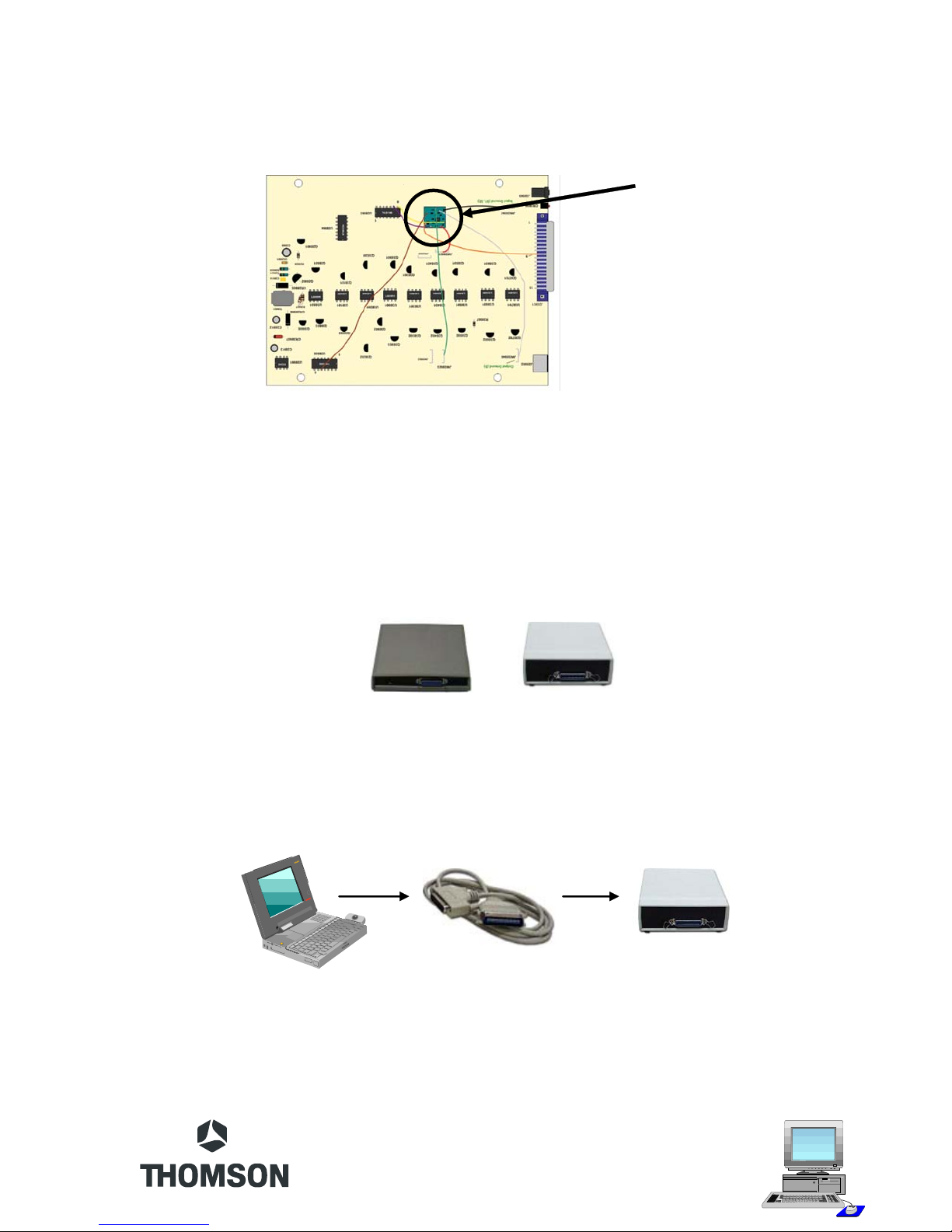
Chipper Check II Interface ................................................................5
Connecting the Interface Box to the PC............................................7
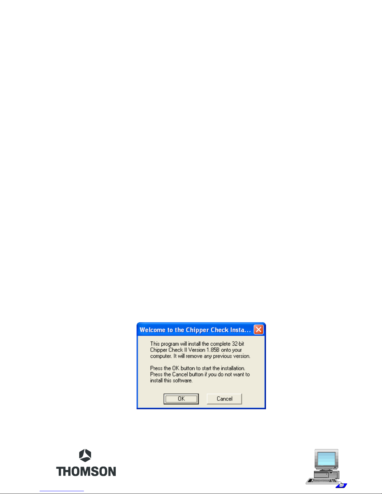
CCII Install Software..........................................................................7
CCII Software Start-UP....................................................................10
Entering the Service Mode ..............................................................13
CTC175, 176, 177, 186 & 187 Setup Procedure...........................14
CTC178, 179, 188 & 189 Setup Procedures .................................16
Procedure: ..................................................................................16
Dead Set .....................................................................................18
CTC195, 197 & 203 Setup Procedures..........................................19
Procedure: ..................................................................................19
Dead Set .....................................................................................20
Setup MM101, MM102, CTC210, CTC211, and LCOS Chassis....20
Procedure: ..................................................................................21
PTV Convergence Setup............................................................21
Dead Set .....................................................................................21
Setup DTV306, DTV307 Chassis ...................................................22
Service Mode (Manually).............................................................22
TECI1 Switch Position ................................................................23
ATC221 and ITC222 Setup Procedure...........................................23
Procedure: ..................................................................................24
Dead Set .....................................................................................24
DLP, ATC311, 321, 322, and 323 Setup.........................................25
Establishing a connection: ..........................................................25
Dead Set .....................................................................................28
Interface Box Diagnostic Tests........................................................29
Frequently Asked Questions ...........................................................34
Contact Phone Numbers .................................................................36

4
What is Chipper Check II (CCII)?
ChipperCheckIIisanadvanced interfaceboxthat providescommunicationbetween theTV
setbeingservicedandapersonalcomputer. TheinterfaceconvertstheI2Cbuscommunication
oftheTV toserialcommunication usedbythe PC. WiththeChipperChecksoftware,thePC
isabletocontrol certain functionsoftheTVand perform some alignments.
OtherfunctionsofCCIIaresoftware upgrade, read error codes,anddownload/restorethe
EEPROM(chassisalignmentdata).
ChipperCheckIIhardware consists of severalitems. Thehardwareitemsare:
•ChipperCheckII interface box
•InterfaceCables(serialand parallel cables)
•TECI1Adapter Board and Cables
•(2) LegacyAdapter Boards
•ITC222Cable
YoucanfindadditionalinformationaboutChipperCheckIIat:http://www.thomsonnetwork.com.
Chipper Check (CC) vs. Chipper Check II (CCII)
The original interface box worked as designed for chassis of it’s time but as technology
progressed,therewas a needtochangethe interface andalongcameCCII. The difference
betweenCC andCCIIisthetri-level logicofCCIIoverthebi-levellogicofCC. BygoingtoTri-
level,CCIIandamodifiedCC would be able to interface withthemoreadvancedchassis.

5
The modification was simple, just add the daughter board to the original CC interfaces and
theCCbecometri-level logic compatible. AmodifiedCCcircuitboardwill look similar tothe
onebelow:
The new interface CCII and a modified CC incorporates the tri-level logic circuit and are
backwardscompatible.
Chipper Check II Interface
Therearetwotypes of interfaceboxes,themodified CF002 andCF003. Atri-levelinterface
istheonlyone that iscompatiblewithcurrent chassis.
ThePurposeofthe interface boxistoallowa PC tobeconnectedtothe TV setviaadapters
andcables.
Tomake theconnectionto thePC,aparallelprinter cableisused. This cableconnectstothe
parallelportonthe PC andtheCentrexendconnects to theinterfacebox.
Daughter Board

6
1
2
3
4
5
6
7
1
2
3
4
5
6
7
1
2
3
4
5
6
1
2
3
4
5
6
7
1
2
3
1
2
3
4
5
6
7
1
2
3
4
5
6
7
A
B
C
D
E
F
ThePS2cableisconnectedbetweentheinterface box and adapter board.
There are 3 adapter boards; two legacy adapters and one TECI1. The TECI1 board has
many plugs and a switch. These plugs are for connecting different cables for the different
chassis. Theswitchis forconvergencecommunicationson PTVproducts. Becauseoftheir
separatebuslines,theconvergencecommunications requires a connection separate from
themainI2C bus. Thelargerthree pinconnectorisfor convergenceI2Cbuscommunication.
Inadditionto theTECI1adapter andcables,there arereplacementsforthelegacyadapters.
These replacement cables connect to the TECI1 adapter and provide connection to older
legacysets.

7
Connecting the Interface Box to the PC
Usingtheparallelcable,locatetheprinterportonthePCandconnectthe25-pinDinconnector
to it. The other end of the printer cable (Centrex connector) connects to the interface box.
Thisistheonly connectionbetweenthePCand theinterfacebox.
Next, connect the serial cable to the interface box and to the appropriate adapter. The
appropriateadapterdependsonwhatchassis isbeingserviced. Do notconnectthe adapter
or cable to the instrument being serviced until instructed to do so by the Chipper Check
software. Eachchassisis different onthesetupand connectionpoint. Informationonsetup
andhookupisfoundinthe Help files of the Chipper Checkprogram.
CCII Install Software
TheChipperCheck softwareisalwayschanging. Tomakesureyouhave thelatestversion,
goto www.thomsonnetwork.net. Under “OrderChipperCheck”,thelatestversionofsoftware
willbeshownandavailable for download. Ifyoualreadyhavethelatest, there is noneedto
downloadthisversion. If not,thendownload thelatestversion.
Oncedownloaded,double clickontheEXEfileandit willselfinstall. Very littleuserinterface
is required for installation. Just follow the on-screen prompts and when done, the PC will
need to be restarted. Restart is necessary because registry information is changed during
theinstalland in orderforthosechanges totakeeffectit requires thecomputerberestarted.
Oncethe PC is restarted, Chipper Check software is ready for use.
Thefirstscreento comeupistheWelcome screen. Thisscreenisthe“are sureyouwantto
install”screen. OptionsareOKor Cancel. OK will start theinstallationandCancelwillstop
theinstallation.
Ifyourupdating apreviousversion ofCCII,theinstall softwarewillautomaticallyremoveany
previousversionofChipperCheck.

8
Thenextuserinputrequiredscreen asksforthe “DestinationDirectory”. Thisis thedirectory
inwhichyouwanttheinstallprogramtostoretheChipperCheckfiles. Itisrecommendedyou
acceptthedefaultlocation but isnotnecessary.
Afterthedestinationisselectedtheinstallationprocessisstartedandtheprogressisdisplayed
forreferenceonly bythefollowinggraphic.
When all the files are copied to the destination folder, a screen is displayed indicating the
default port is LPT1. This is the communications port Chipper Check interface uses to
communicate with the PC. If you are already using LPT1 for a printer or other peripheral
device,youmustchangethe INIfiletoindicatewhichporttouse. The onlyoptionsare LPT1,
LPT2,orLPT3. SelectOKto accept the default LPT1 port.

9
Next is the program group selection. It is recommended you select the default location but
not necessary. This will allow you to customize where you launch Chipper Check program
from.
Thelastwindowdisplayedwillindicatethatchangeshavebeenmadetothecomputerregistry
andthePC willneedtobe rebooted beforethechangeswill takeeffect. Thisisimportant for
Chipper Check operation. Failing to reboot can result in Chipper Check failure. Once the
PCisrebooted,ChipperCheck will function correctly.

10
CCII Software Start-UP
To start the Chipper Check software, locate the start button on the task bar with the mouse
pointerandclick it. Thenpointto “Programsandlocatethe programgroup“Chipper Check”.
Onceinthe programgroupofChipper Check,locatetheCCII programiconand clickit. This
willlaunchthe ChipperChecksoftware.
Thefirsttime CCII softwareisrun,the ServicerInformationentryscreen is thefirstscreento
appear. Once filled in,thisscreenwillnotreappear. The Servicer Informationentryscreen
allowstheServicertopersonalize their versionofChipperCheck.
Optionsare:
•Fillinallinformationandclickonthe“OK”button. Thiswillpreventthisentry screen
frombeingdisplayedagain.
•Select“Cancel” buttontobypasswithoutenteringany information. Doingsowillallow
futurestartsofChipper Check todisplaythisentry screen.
•The“Help”button launchesapop-up windowdisplayinghelpinformation.
Dependingontheversionofsoftware,themainscreendisplayedaftertheServicerInformation
screenisthestartscreenofChipperCheck. Inthefollowingexample(Version 1.86), there
areseveraloptionsdependingonwhatchassisisbeingserviced.

11
More information about the software can be found in the Help files within Chipper Check
Software.
Onescreenfound in allChipperCheckversions isthe“CustomerInformation Screen”. This
screenallows thetechniciantoenteruniqueinformationtogeneratea fileofthestoredvalues
inthemainEEPROM oftheinstrumentbeingserviced. This file canlaterbeused to restore
a corrupt EEPROM for this customer. Since this information is unique to each instrument,
ModelandSerialnumbers are required to proceed past this screen.
Thereare threeoptionsforthistab. One ofthethreehasto becompletedbeforetheprogram
willallowothertabstobe selected. The options are:
1. Openfile
2. Savefile
3. EnterModel andSerialnumbers
If only generic model and serial numbers are used, the technician will not want to save this
information. Saving with generic information can cause the wrong file to be loaded thus
causingadditionalproblemsfor the technician/customer.
The store and open file are optional. By storing the information the technician is creating a
fileforfutureuse. TheopenfileallowsthetechniciantoutilizethesavedfilefeatureofChipper
Checkatalatterdate. Inotherwords,ifthe techniciansavedthe filethefirst timeinfor repair
and later the set needed the EEPROM replace, the alignment process would be almost

12
eliminatedbyrestoringthecustomerfile forthatset. The onlyrequirementwould belocating
thecorrectfile and restoringittothe customersset. TheModeland Serial numberfieldsare
thebestwaytodistinguish betweeninstruments. Becauseof this,themodel andserialfields
needtobefilledintoadvancein the program.

13
Entering the Service Mode
Duringnormaloperation,newerchassis(CTC195,197,203,210,211,MM101,102,DTV306,
307, and LCOS) are continuously monitoring the I2C bus for an acknowledgment from the
EEPROMthat residesintheChipperCheckinterfacebox. When thesenewerchassisdetect
thattheChipperCheckEEPROMhasbeenconnectedtotheI2Cbus,thechassisautomatically
gointotheService Mode. The chassismustsupplytheI2Cclockduringthis auto-detection,
whichunfortunately,runsapproximately 5timesfaster thantheChipperCheckinterfacebox.
Theinterfacebox suppliestheI2Cclock oncethechassis isintheService Mode. Thespeed
oftheI2Cclockfrom the chassis,combinedwiththe extra resistanceandcapacitanceof the
interfacecablesandtheinterface box,willoccasionally preventtheEEPROMauto-detection
fromworking. Whentheauto-detectiondoesnot work,usethe manualproceduredescribed
below. When the auto-detection doesnotwork,thechassiswill usually shut downandmay
havetobeunpluggedbefore it will power upagain.
Manuallyputtingtheinstrumentinto theservicemode:
Thisroutine applies to all chassis except DTV306 and DTV307.
1. WiththeinstrumentON, pressandhold theMenubutton.
2. Pressand releasethePowerbuttonthen press andreleasetheVolumeUPbutton.
3. Release the Menu button and the instrument should display the ROM version, a ‘P’
number(parameter),and a‘V’number (value).
4. Usingeithertheremotehandunitorthefrontpanelbuttons,pressandholdtheVolume
DOWNbuttonuntil the‘V’valuedisplays 200.
5. Nowpress theChannelUPbutton to entertheservicemode.
Aftertheinstrument isintheservice modetheinterface boxmaybeconnected. Ifconnected
totheinterfacebox andtheinstrumentisNOT intheservicemode,the instrumentmayshut
down. Ifthishappens,ACpowermustbe removed to restarttheset. Oncethe chassis isin
theservicemode and theinterfaceisconnected to thechassis,ChipperCheck software will
beabletocommunicatewith the set.

14
CTC175, 176, 177, 186 & 187 Setup Procedure
ConnectingtheChipperCheck interface box tothechassisrequiresthe following:
1. InterfaceBox
2. ParallelPrinterCable
3. InterfaceCable212118
4. Adapter Board 212121
TheonlyfunctionChipperCheckcan performonthese chassisisinitializing theEEPROMto
factorysettings.
1. Theset MUSTbeOFFandUNPLUGGED when initializing theEEPROM.
2. Youmust determineifthesethasaMotorola orSTmicroprocessor(U3101)U3101is
marked with either ST or Motorola. If the IC is a Motorola ground pin 1, if the IC is
marked ST ground pin 2. Retain this ground while the EEPROM is being initialized.
Oncereinitialized,remove the groundbeforereturningthe set tonormaloperation.
3. PriortoinitializingtheEEPROM,anexternal5volt supply and a 1K resistor must be
connectedperthe diagramonthenext page. DONOTapply theexternal5volts until
afterthechassisisselected intheChipper Checksoftware. If5voltsisappliedbefore
thechassisis selected aNOCOMMUNICATIONS errormayresult.

15
F
D
E
IC D
E
F
5V
EEPROM
Schematic Diagram
Thediagram belowshowshowtoconnecttheadaptertothechassis. Adapterboard212121,
7 jumper wires and an IC clip are used to connect the Chipper Check interface box to the
EEPROM. You may connect leads directly to the EEPROM or use an IC clip. The IC clip
shown in the diagram is a Pomona clip, Pomona part number 5108, available from most
partssuppliers.

16
CTC178, 179, 188 & 189 Setup Procedures
ConnectingtheChipperCheck interface box tothechassisrequiresthe following:
1. InterfaceBox
2. ParallelPrinterCable
3. InterfaceCable212118
4. Adapter Board 212117
Things to Consider:
Donotconnecttheinstrumenttotheinterfaceboxuntil theinstrumentisonand intheservice
mode.
Beforeputtingthe instrumentintotheservicemode,presetthe volumetoalow level. Donot
setthevolume toabsoluteminimumor ChipperCheckwillnot beabletocontrol thevolume.
Once the instrument is in the service mode, it is not possible to adjust the volume from the
frontpanelor remotecontrol.
When the instrument is in the service mode, the main microprocessor is in a “slave” mode
andwillnot respondtoany remotecommandsor frontpanelkeypresses. Inordertoexit the
servicemode,itisnecessary to removeAC power from theinstrument.
Iftheinstrumentwillnotturn onbutthe standbysuppliesare functioning,thenitispossibleto
readtheerrorcodesstoredinthemainEEPROMbyusingthe“DeadSet”procedure.
Procedure:
ConnectthePC,Interface box, andadapterboardtogetherusing the correct cables.

17
1. Placethe instrumentintheservice mode.
a. WiththeinstrumentON,pressandholdtheMenubutton,pressandreleasethe
powerbuttonthenpress and releasethevolume+ button. Release theMenu
button. Theinstrumentshould now displaytheROMversion andP:00V:00.
b. Usingtheremotehandunitorthefrontpanelbutton,pressandholdthevolume
(-)untilthe“V” valueis200.
c. NowpresstheChannel “up”buttontoenter the servicemode.
2. Connecttheadapterboardtothe interfaceplugJ3104(location20BB)onthechassis.
3. StartChipperCheckProgram and select the Detect Chassis button.
Ifcommunicationisnot established,thefollowingscreenwill be displayed.

18
1. RemoveAC power fromtheinstrumentbydisconnecting theAC power cord.
2. Clickonthe“Deadset”buttonin the main screen of theChipperChecksoftware.
3. Select the correct TV chassis for the instrument being tested and click on the OK
button. ThisbringsupChipperCheckVersion1.93.
4. Clickon theOKbuttonto open theCustomerFileInformation.
5. ClickontheOKbuttonto bring up the setupscreenwithaDeadSetbutton.
6. ClickontheDeadSetbutton to open up thechassisselectionbuttons.
7. Selectthe appropriatechassisbutton
8. Connecttheadaptertotheinstrument chassis
9. Plugin theTV.
10.ClickOKandChipperChecksoftware will read the error codes storedinthechassis
EPROManddisplay them.
Dead Set
Ifthesetwill notstartup,theEEPROMerrorcodeinformationcanstillbeobtainedbyChipper
Check. The EEPROM may also be tested for proper hardware operation, but keep in mind
thatevenifthe EEPROM is OK,thesoftwareinformationcontainedin it maybecorrupt.

19
CTC195, 197 & 203 Setup Procedures
ConnectingtheChipperCheck interface box tothechassisrequiresthe following:
1. InterfaceBox
2. ParallelPrinterCable
3. InterfaceCable212118
4. Adapter Board 212121
Things to Consider:
Beforeputtingtheinstrumentinto the service mode,presetthevolumetoa low level. Once
the instrument is in the service mode, it is not possible to adjust the volume from the front
panelorremote control.
Do not connect the instrument to the interface box until the instrument is on, in the Service
Mode,andthe Chipper Checkprogramisrunning withthefirstscreen of theprogramvisible
(theparallelport isinitializedjustprior tothefirstscreen beingdisplayed). Failuretocomply
withthisrequirementmaycausetheinstrumenttoshutdown.
Oncetheinstrument isplacedintothe service mode,themainmicroprocessor isplacedinto
the“slave”mode. It willnotrespond toanyremotecommands orfrontpanel keypresses. In
ordertoexittheservice mode, it is necessarytoremoveAC powerfromtheinstrument.
Iftheinstrumentwillnot turnon,itisstillpossibletoread errorcodesin themainEEPROMas
longasthestandbysuppliesarefunctioning. Goto the“DeadSet” sectionforthe procedure.
ftheinstrument willnotturnon but thestandbysuppliesare functioning,thenitis possibleto
readtheerrorcodesstoredinthemainEEPROMbyusingthe“DeadSet”procedure.
Procedure:
1. Put the CTC195, 197 or 203 into the Service Mode.
2. WiththecomputerOFF,connectyourcomputertotheinterfaceboxusingthestandard
parallelprintercable.
3. Apply power to the Chipper Check interface box CCF002.

20
4. Turnthecomputer onandstartthe ChipperChecksoftware. DONOTtrytodetectthe
chassis at this time!
5. Connecttheinterfacecabletothe212121adapterboard.
6. Connect the adapter board to J13120 (CTC195/197), or J13101 (CTC203) on the
chassis.
7. Connectthe interfacecabletothe interface box.
8. Pressthe “DetectChassis”button.
The CTC203 service connector (J13101) is at board locationAA-6 near the power switch.
The CTC195/197 (J13120) service connector is at board location KK-6.
Dead Set
1. RemoveAC power fromtheinstrumentbydisconnecting theAC power cord.
2. Clickonthe“Deadset”button in the mainscreen.
3. Select the correct TV chassis for the instrument being tested and click on the OK
button.
4. Followthe instructionsdisplayedbyChipper Check software.
Deadset proceduresmaydifferslightlybychassis. Itis importanttofollowtheinstructionsfor
thechassisbeingservicedto ensure propercommunication.
Setup MM101, MM102, CTC210, CTC211, and LCOS Chassis
ConnectingtheChipperCheck interface box tothechassisrequiresthe following:
1. InterfaceBox
2. ParallelPrinterCable
3. InterfaceCable212118
4. TECI1Adapter
Things to Consider:
Table of contents
Other THOMSON Pet Care Product manuals
Popular Pet Care Product manuals by other brands

Carlson Pet Products
Carlson Pet Products 6002 owner's manual

TITO
TITO CANE-M quick start guide

Qpets
Qpets AF 108 user manual

Automated Pet Care Products
Automated Pet Care Products litter-robot open air instruction manual

SportDOG
SportDOG SportTrainer 875 quick start guide

Flamingo
Flamingo Galaxy quick start guide

Trixie
Trixie REPTILAND Fogger XL Instructions for use

Dogtra
Dogtra 200C user manual

SportDOG
SportDOG TEK-V1.5LT operating guide

Double K Industries
Double K Industries Challengair 2000 Plus instruction manual

SHOR-LINE
SHOR-LINE Kat Klowder Assembly guide

Petsafe
Petsafe Electronic SmartDoor quick start guide