dibea KB004 User manual


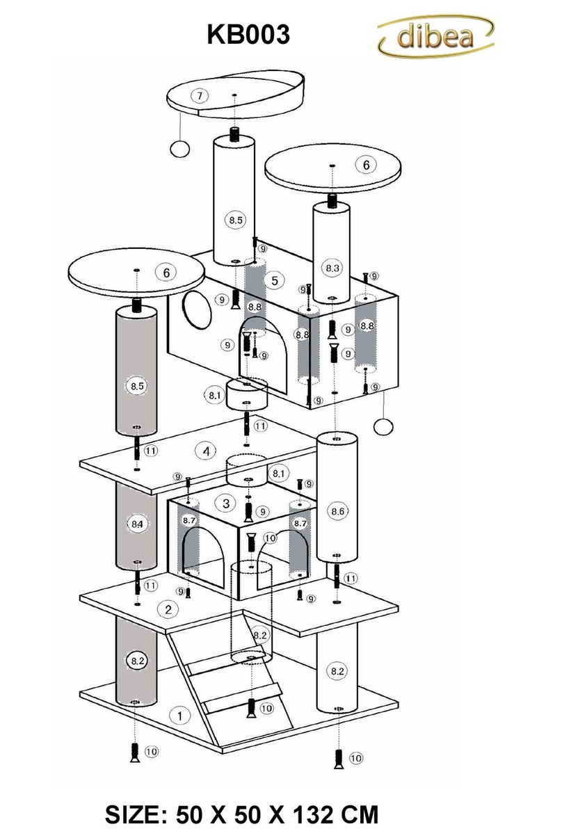
LIEFERUMFANG / PARTS LIST / ETENDUE DE LA LIVRAISON
Nummer
/ Part Number
/ Numéro
Beschreibung / Description / Description
Maße in mm
/ Measurement( mm) /
Dimensions en mm
Menge
/ Quantity
/ Quantité
P1 Bodenplatte / Bottom plate / Plaque de base 600 X 450 1
P2 Liegeplatte / Lying plate / Plate-forme 350 X 300 1
P3.1 Höhle / Cave / / Caverne
(Ten screw holes) 450 X 350 X 250 1
P3.2 Höhle / Cave / / Caverne
(Nine screw holes) 450 X 350 X 250 1
P4 Liegeplatte / Lying plate / Plate-forme 600 X 450 1
P5 Liegeplatte / Lying plate / Plate-forme 550 X 300 1
P6 Treppe / Stair / Escalier 425 X 60 4
P7 Deckenspanner / Telescopic assembling
/ Fixation au plafond Φ=100 1
P8 Röhre / Playing roll / Tube pour se cacher Φ = 220 L = 250 1
P9.1-P9.7 Kratzstangen / Post / Griffoirs Ф80~Ф55~Ф50 21
P10 Liegemulde / Round hammock / Hamac Φ = 300 2
P11 Gewindeschraube / Rounded head screw
/ Vis filetée M8 X 20 8
P12 Gewindeschraube / Rounded head screw
/ Vis filetée M8 X 25 1
P13 Gewindeschraube / Rounded head screw
/ Vis filetée M8 X 35 18
P14 Gewindeschraube / Rounded head screw
/ Vis filetée M8 X 50 9
P15 Unterlegscheibe / Washer / Rondelle M8 1
P16 Doppelgewinde / Thread rod / Double filetage M8 X 65 7
P17 Inbusschlüssel / Wrench / Clé Allen M8 1
P18 Metallwinkel / Metal Plates / Equerre métallique 30 X 30 4
P19 Abschlussscheibe / Round plate / Tranche Φ=300 1
P11 Gewindeschraube / Rounded Head Screw / Vis filetée
P12 Gewindeschraube / Rounded Head Screw / Vis filetée
P13 Gewindeschraube / Rounded Head Screw / Vis filetée
P14 Gewindeschraube / Rounded Head Screw / Vis filetée
P15 Unterlegscheibe / Washer / Rondelle

P16 Doppelgewinde / Thread rod / Double filetage
P17 Inbusschlüssel / Wrench / Clé Allen
P18 Metallwinkel / Metal Plates / Equerre métallique
P19 Abschlussscheibe / Round plate / tranche
4PCS 4PCS 2PCS 2PCS 6PCS 1PC 2PCS
AUFBAUANLEITUNG / ASSEMBLY INSTRUCTIONS /
INSTRUCTIONS DE MONTAGE
(DE) Bevor Sie beginnen, achten Sie beim Aufbau des Kratzbaums darauf, welche Kratzstämme
mit Stoff und Sisal und welche ausschließich mit Stoff überzogen sind. Letztere sind in den
Zeichnungen schwarz markiert.
(GB) Before you begin, please distinguigh the sticks that are covered with sisal and fabric from
those that are only covered with fabric. The latter ones are marked black in the sketch
(FR) Avant de commencer, lors du montage de l’arbre à chat, prêtez attention aux griffoirs revêtus
d’étoffe et de sisal et à ceux entièrement revêtus d’étoffe. Ces derniers sont marqués en noir dans
les dessins.
1)
(DE) Befestigen Sie mit Hilfe der Gewindeschrauben P13 2 Kratzstämme mit einer Länge von 350
mm (P9.5) auf der linken und mittleren Position und 1 Kratzstamm mit einer Länge von 468 mm
(P9.7) auf der rechten Position der Bodenplatte (P1).
Verbinden Sie nun mit Hilfe eines Doppelgewindes (P16) die Liegeplatte P2 mit einem Kratzstamm
mit einer Länge von 468 mm (P9.7). Befestigen Sie als nächstes einen weiteren Kratzstamm mit
einer Länge von 468 mm (P9.7) mit der Liegeplatte (P2) indem Sie diesen auf das Doppelgewinde
aufschrauben.
Schrauben Sie nun die Röhre (P8) mit einer Gewindeschraube (P12) und der Unterlegscheibe
(P15) an der Liegeplatte (P2) fest.

Aufbau der Höhle:
Benutzen Sie nun 2 Kratzstämme (P9.2) um die unter Höhle (P3.1) aufzurichten und befestigen
Sie diese mit Gewindeschrauben (P13) jeweils von unten und von oben. Die Höhle weist
(abgesehen von den Schraubgewinden für die Leiter) auf der Ober- und Unterseite jeweils 4
Löcher auf. Achten Sie beim Befestigen der Kratzstämme P9.2 darauf, dass Sie 1 Stamm vorne
links und 1 Stamm hinten rechts positionieren. Nur mit dieser Positionierung kann der Kratzbaum
weiter aufgebaut werden.
Befestigen Sie unter Verwendung von Gewindeschrauben (P13) die nun aufgebaute Höhle (P3.1)
auf den linken und mittleren Kratzstämmen (P9.5) der Bodenplatte (P1).
(GB) Attach 2 scratching posts measuring 350 mm (P9.5) to the left and middle position and 1
scratching post measuring 468 mm (P9.7) to the right position on the floor plate (P1) using
threaded screws (P13).
Now use a double-thread (P16) to connect the flat panel (P2) to a scratching post measuring 468
mm (P9.7). Then attach a second scratching post measuring 468 mm (P9.7) to the flat panel (P2)
by screwing it onto the double-thread.
Screw the pipe (P8) to the flat panel (P2)with a threaded screw (P12) and the washer (P15).
Assembling the cave:
Use 2 scratching posts (P9.2) to secure the lower part of the cave (P3.1) and attach these using
threaded screws (P13) both above and below. The cave has 4 holes on each of its upper and lower
surfaces in addition to the screw threads for the ladder. When attaching the scratching posts (P9.2),
ensure that you position 1 post at the front left and 1 post at the back right. The scratching tree can
only be properly assembled with this positioning.
Use threaded screws (P13) to secure the newly attached cave (P3.1) to the left and middle
scratching posts (P9.5) on the floor plate (P1).
(FR) A l’aide des vis filetées P13, fixez deux griffoirs d’une longueur de 350 mm (P9.5) sur la
position de gauche et centrale et un griffoir d’une longueur de 468 mm (P9.7) sur la position de
droite de la plaque de base (P1).
A présent, à l’aide d’une vis à double filet (P16), reliez la plate-forme P2 à un griffoir d’une
longueur de 468 mm (P9.7). Fixez ensuite un autre griffoir d’une longueur de 468 mm (P9.7) sur la
plate-forme en vissant celle-ci sur le double filetage.
A présent, vissez et serrez les tubes (P8) avec une vis filetée (P12) et la rondelle (P15) sur la
plate-forme.
Assemblage de la caverne :
Utilisez à présent deux griffoirs (P9.2) pour les placer sous la caverne (P3.1) et fixez celle-ci avec
des vis filetées (P13), en haut et en bas. La caverne présente (abstraction faite des filets de vis
pour l’échelle) quatre trous sur le dessus et quatre sur le fond. Lors de la fixation des griffoirs P9.2,
veillez à positionner un griffoir devant à gauche et un derrière à droite. C’est seulement dans cette
position que l’on peut continuer à assembler l’arbre à chat.
Fixez, au moyen de vis filetées (P13) la caverne désormais assemblée (P3.1) sur les griffoirs de
gauche et du milieu (P9.5) de la plaque de base (P1).
2.
(DE) Schrauben Sie 2 weitere Kratzstämme mit einer Länge von 350 mm (P9.5) mit Hilfe von 2
Gewindeschrauben (P13) aus dem Inneren der Höhle (P3.1) auf dieser fest.
Aufbau der Treppen:
Verschrauben Sie 2 Kratzstämme mit einer Länge von 160 mm (P9.1) unter Verwendung von
Gewindeschrauben (P14) beidseitig mit den Treppenseiten (P6). Befestigen Sie die beiden
Metallwinkel (P18) mit der Treppe (P6) und verwenden Sie dazu Gewindeschrauben (P11).
Danach verbinden Sie die Treppe (P6) mit der Höhle (P3.1) und verwenden dazu
Gewindeschrauben (P11).
(GB) Attach 2 additional scratching posts measuring 350 mm (P9.5) securely to the cave using 2
threaded screws (P13) from the inside of the cave (P3.1).
Assembling the stairs:
Screw 2 scratching posts measuring 160 mm (P9.1) with threaded screws (P14) to the sides of the
stairs (P6). Attach both metal brackets (P18) to the stairs (P6) and then use the threaded screws
(P11). Then connect the stairs (P6) with the cave (P3.1) using threaded screws (P11).
(FR) Vissez et serrez deux autres griffoirs d’une longueur de 350 mm (P9.5) à l’aide de deux vis à
filet (P13) depuis l’intérieur de la caverne (P3.1) sur celle-ci.
Assemblage des escaliers :
Vissez deux grattoirs d’une longueur de 160 mm (P9.1) au moyen de vis filetées (P14) des deux
côtés sur les côtés de l’escalier (P6). Fixez les deux équerres métalliques (P18) sur l’escalier (P6)
au moyen de vis filetées (P11). Puis reliez l’escalier (P6) à la caverne (P3.1) au moyen de vis
filetées (P11).

3.
(DE) Befestigen Sie die Liegeplatte (P4) mit Hilfe von 3 Doppelgewinden (P16) mit den
freistehenden Kratzstämen P9.7 und P9.5. Schrauben Sie nun 2 weitere Kratzstämme mit einer
Länge von 300 mm (P9.4) auf der rechten und mittleren Position und 1 Kratzstamm mit einer
Länge von 410 mm (P9.6) auf der linken Position auf die Doppelgewinde auf.
(GB) Attach the flat panel (P4) using 3 double-threads (P16) with the freestanding scratching posts
(P9.7 and P9.5). Now screw 2 additional scratching posts measuring 300 mm (P9.4) to the right
and middle position and 1 scratching post measuring 410 mm (P9.6) to the left position on the
double-thread.
(FR) Fixez la plate-forme (P4) à l’aide de trois vis à double filet (P16) aux griffoirs libres P9.7 et
P9.5. Puis vissez deux autres griffoirs d’une longueur de 300 mm (P9.4) en les positionnant à
droite et au milieu et un griffoir d'une longueur de 410 mm (P9.6) à gauche sur le double filetage.

4.
(DE) Befestigen Sie nun die Liegeplatte (P5) mit Hilfe von 2 Doppelgewinden (P16) auf den beiden
soeben festgeschraubten Kratzstämmen (P9.4). Die Liegeplatte (P5) wird dabei schräg positioniert.
Anschließend schrauben Sie 1 Kratzstamm mit einer Länge von 255 mm (P9.3) auf der rechten
Position und einen weiteren Kratzstamm mit einer Länge von 350 mm (P9.5) auf der mitleren
Position auf den Doppelgewinden (P16) der Liegeplatte (P5) fest. Befestigen Sie mit einer
Gewindeschraube (P14) und einer Abschlussscheibe (P15) nun die Liegemulde (P10) auf dem
rechten Kratzstamm P9.3. Schrauben Sie nun mit Hilfe eines Doppelgewindes (P16) eine weitere
Liegemulde (P10) auf dem linken Kratzstamm (P9.6) fest. Verbinden Sie anschließend einen
Kratzstamm mit einer Länge von 255 mm (P9.3) durch Aufschrauben auf das Doppelgewinde mit
der Liegemulde.
(GB) Then attach the flat panel (P5) using 2 double-threads (P16) to both of the scratching posts
(P9.4) you have just attached. The flat panel (P5) is positioned at a slant. Then affix 1 scratching
post measuring 255 mm (P9.3) to the right position and another scratching post measuring 350
mm (P9.5) to the middle position on the double-thread (P16) of the flat panel (P5). Use a threaded
screw (P14) and a closure disc (P15) to attach the bed (P10) to the right scratching post (P9.3).
Now screw another bed (P10) onto the left scratching post (P9.6) using a double-thread (P16).
Then connect one scratching post measuring 255 mm (P9.3) by screwing the double-thread onto
the bed.
(FR) Fixez maintenant la plate-forme (P5) à l’aide de deux vis à double filet (P16) sur les griffoirs
que vous venez de fixer (P9.4). La plate-forme (P5) est alors positionnée en biais. Puis vissez et
serrez un griffoir d’une longueur de 255 mm (P9.3) du côté droit et un griffoir supplémentaire d'une
longueur de 350 mm (P9.5) en position centrale sur les doubles filetages (P16) de la plate-forme
(P5). A présent, fixez avec une vis filetée (P14) et une rondelle d’obturation (P15) le hamac (P10)
sur le griffoir de droite P9.3. Puis vissez à l’aide d’un double filetage (P16) un autre hamac (P10)
sur le griffoir de gauche (P9.6). Reliez ensuite un griffoir d’une longueur de 255 mm (P9.3) en le
vissant sur le double filetage avec le hamac.

5.
(DE) Richten Sie die zweite Höhle (P3.2) mit der in Schritt 1 beschriebenen Vorgehensweise auf.
Die nun aufgebaute Höhle (P3.2) wird anschließend unter Verwendung von Gewindeschrauben
(P13) aus dem Inneren der Höhle mit den linken und mittleren Kratzstämmen (P9.3, P9.5)
verbunden.
(GB) Set up the second cave (P3.2) as in Step 1 above. Now use threaded screws (P13) on the
inside of the cave (P3.2) to attach it to the left and middle scratching posts (P9.3, P9.5).
(FR) Placez la deuxième caverne (P3.2) de la manière décrite à l’étape 1. La caverne désormais
montée (P3.2) est ensuite reliée au moyen de vis filetées (P13) depuis l’intérieur de la caverne aux
griffoirs de gauche et du milieu (P9.3, P9.5).

6.
(DE) Bauen Sie eine weitere Treppe (P6) mit der in Schritt 2 beschrieben Vorgehensweise auf und
befestigen Sie die anschließend unter Verwendung von Gewindeschrauben (P11) mit der Höhle
P3.2.
Ein an dieser Stelle häufig auftretendes Problem ist, dass die Leiter nach Befestigung an der Höhle
nicht wie auf der Abbildung zu sehen auf dem Liegebrett P5 zu stehen kommt. Dies ist ein Resultat
aus der falschen Positionierung der Kratzstangen im Inneren der Höhle. Durch das Vertauschen
der Löcher wird die Höhle nicht wie gewünscht Positioniert. Bitte lesen Sie an dieser Stelle
nochmal die in Schritt 1 beschriebene Vorgehensweise zum Aufbau der Höhlen.
(GB) Assemble another staircase (P6) as in Step 2 above and attach it to the cave (P3.2) using
threaded screws (P11).A frequent problem at this stage is that, once it is attached to the cave, the
ladder does not stand on the flat panel (P5) as shown in the picture. This is due to improper
positioning of the scratching post inside the cave. If the wrong holes are used, the cave is not
positioned properly. Please re-read the descriptions given in Step 1 above about assembling the
cave.
(FR) Montez un escalier supplémentaire (P6) de la manière décrite à l’étape 2, puis fixez-le au
moyen de vis filetées (P11) à la caverne (P3.2).
Un problème survenant fréquemment à ce moment est que, après avoir fixé l'échelle à la caverne,
elle ne se place pas sur la planchette P5 comme on le voit sur l'illustration. Cela signifie que les
barres-griffoirs à l'intérieur de la caverne sont mal positionnées. Du fait de l’échange des trous, la
caverne ne se positionne pas comme souhaité. Veuillez lire encore une fois ici la procédure décrite
à l’étape 1 pour monter les cavernes.

7.
(DE) Befestigen Sie nun einen Kratzstamm mit einer Länge von 350 mm (P9.5) mit Hilfe einer
Gewindeschraube (P13) aus dem Inneren der Höhle (P3.2) auf dieser fest. Zum Schluss verbinden
Sie den Deckenspanner (P7) durch Aufschrauben mit dem Kratzstamm (P9.5). Der
Deckenspanner sollte nun durch herausdrehen mit der Decke verbunden werden, um eine
optimale Stabilität des Produkts gewährleisten zu können.
(GB) Use a threaded screw (P13) on the inside of the cave (P3.1) to attach it securely to a
scratching post measuring 350 mm (P9.5). Finally, connect the ceiling connector (P7) by screwing
it onto the scratching post (P9.5). The ceiling connector should now be connected to the ceiling by
screwing it into position in order to ensure maximum stability of the product.
(FR) A présent, vissez et serrez un griffoir d’une longueur de 350 mm (P9.5) à l’aide d’une vis
filetée (P13) depuis l’intérieur de la caverne (P3.2) sur celle-ci. Pour terminer, reliez la fixation au
plafond (P7) en la vissant sur le griffoir (P9.5). La fixation au plafond devrait à présent être reliée
au plafond par rotation, pour pouvoir garantir une stabilité optimale du produit.

(DE) Bei ggf. auftretenden Problemen steht Ihnen unser Kundenservice gerne zur Seite. Gerne
können Sie uns dazu mit Hilfe der unten stehenden Kontaktdaten kontaktieren. Wir danken Ihnen
für Ihren Einkauf und wünschen Ihnen viel Freude an Ihrem Produkt.
(GB) If there are any problems, our customer service will be happy to help you out. You can reach
us with the contact details you see below.Thank you for purchasing our product. We hope you'll
enjoy it.
(FR) En cas de problèmes éventuels, notre service après-vente se fera un plaisir de vous assister.
N’hésitez pas à nous contacter aux coordonnées figurant ci-dessous. Nous vous remercions de
votre achat et vous souhaitons beaucoup de plaisir avec votre produit.
SICHERHEITSHINWEISE / SAFETY INFORMATIONS / CONSIGNES DE SÉCURITÉ DE
(GE) Dieses Produkt wurde für die Verwendung als Kratz- und Kletterbaum für Katzen hergestellt.
Jegliche davon abweichende Verwendung durch den Verbraucher geschieht auf eigene Gefahr.
Der Umbau des Produkts und die Veränderung der in der Aufbauanleitung dargestellten
Konstruktion geschieht auf eigene Gefahr.
Das Produkt muss an einem Platz mit stabilem Untergrund platziert werden.
(GB) This item was produced for the use as a scratching and climbing post for cats. Any other use
deviating from that purpose is seen as the customer's own risk.
Also, the alteration of the product other than shown in the assembly instructions is seen as the
customer's own risk.
The product is to be placed on even and stable ground.
(FR) Ce produit a été fabriqué pour être utilisé comme arbre à chat. Toute utilisation autre par le
consommateur a lieu à ses propres risques.
La transformation du produit et la modification de la construction représentée dans les instructions
de montage ont lieu à vos propres risques.
Le produit doit être positionné à un endroit où le sol est stable.
Adress: Fa. Dibea Siemenstraße 89 47574 Goch
Tel: +49 28 23 / 97 55 85 0
Email: service@dibea.de
Websit: www.dibea.de
Other dibea Pet Care Product manuals
Popular Pet Care Product manuals by other brands

Catnets
Catnets Lite Double 2.3m Portable Cat Enclosure manual

Martin Sellier
Martin Sellier DYNAVET MasterPlus Pro quick start guide

Petsafe
Petsafe IF-100 user manual

Petainer
Petainer PET916N quick start guide

TBI PRO Engineering
TBI PRO Engineering TBI Bark V7 Pro manual

Innotek
Innotek SD-2000 quick start guide

Prevue Hendryx
Prevue Hendryx 3453 quick start guide

Tesla
Tesla SMART LASER DOT CAT user manual

Prevue Hendryx
Prevue Hendryx FeatherStone Heights Victorian Assembly instructions

Pet Fit Designs
Pet Fit Designs Tall Tiger User manual & assembly instructions

High Tech Pet
High Tech Pet Power Pet installation instructions

Dogtra
Dogtra 2300NCP EXPANDABLE owner's manual