Thonk MA VCA User manual

!
!
September 8th 2014 www.thonk.co.uk 1
Manhattan Analog
VCA Module
Eurorack DIY Kit
Instructions
Version 1.0
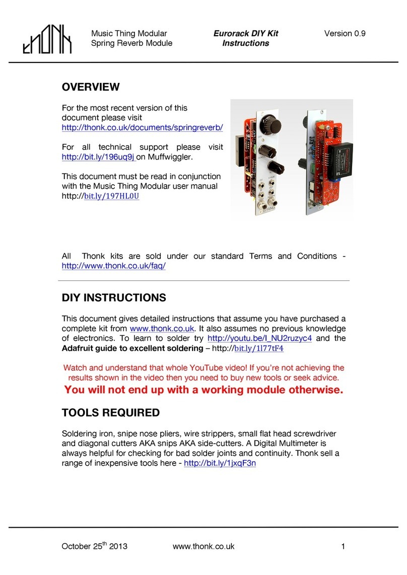
MA VCA OVERVIEW
For the most recent version of
this document please visit
http://thonk.co.uk/documents/MA/
For all technical support please
visit http://bit.ly/1tl78E0 on
Muffwiggler.
All Thonk kits are sold under our standard Terms and Conditions -
http://www.thonk.co.uk/faq/
DIY INSTRUCTIONS
This document gives detailed instructions that assume you have purchased a
complete kit from www.thonk.co.uk. It also assumes no previous knowledge
of electronics. To learn to solder try http://youtu.be/I_NU2ruzyc4 and the
Adafruit guide to excellent soldering – http://bit.ly/1l77tF4
Watch and understand that whole YouTube video! If you’re not achieving the
results shown in the video then you need to buy new tools or seek advice.
You will not end up with a working module otherwise.
TOOLS REQUIRED
Soldering iron, tweezers for SMD parts, snipe nose pliers, wire strippers,
small flat head screwdriver and diagonal cutters AKA snips AKA side-
cutters. A Digital Multimeter is always helpful for checking for bad solder
joints and continuity. Thonk sell a range of inexpensive tools here -
http://bit.ly/1jxqF3n

!
!
September 8th 2014 www.thonk.co.uk 2
Manhattan Analog
VCA Module
Eurorack DIY Kit
Instructions
Version 1.0
SOLDER JOINTS
Your solder joints should look like those shown as ‘OK’ below, they should
have that neat conical shape on BOTH sides of the PCB. If they don’t look
the same on both sides then stop! Work out why from the soldering guides
linked and don’t continue until you are getting those results.
This isn’t about perfectionism, you are very likely to end up with a destroyed,
damaged or defective unit if you’re not hitting that standard.
This photo is from the Adafruit guide to excellent soldering - bit.ly/1l77tF4
and is reproduced under an Attribution-Sharealike creative commons license
- http://creativecommons.org/licenses/by-sa/3.0/

!
!
September 8th 2014 www.thonk.co.uk 3
Manhattan Analog
VCA Module
Eurorack DIY Kit
Instructions
Version 1.0
VCA BUILD INSTRUCTIONS
1.
Start by emptying the whole of the VCA
bag into a bowl or container. This makes
it much easier to pick parts as you need
them and you’re a lot less likely to lose
anything.
2.
First you will solder the three 0.1uF SMT
capacitors.
When you remove the SMT parts from the
white plastic packaging I highly advise
doing so inside a bowl or smooth box with
some soft white tissue paper inside.
Carefully peel back the transparent plastic
with the parts angled down so they fall
into the receptacle. The tissue paper will
stop them bouncing and sliding. If the
receptacle is big enough to fit the PCB in
while you solder even better, then when
you move the part to the PCB for
soldering you remove the chance of losing
them.
Soldering the type of SMT parts included
with this kit is not hard if you have
tweezers. You have no tricky multi pin
SMT IC’s or anything of that nature to
deal with in this kit.
Good technique is important though. This
video is a great introduction to the
standard way of soldering SMT resistors
and caps by hand:
http://youtu.be/PU7wLcuqc-I

!
!
September 8th 2014 www.thonk.co.uk 4
Manhattan Analog
VCA Module
Eurorack DIY Kit
Instructions
Version 1.0
3.
Using the same technique as previously,
solder the ‘1K tcr’ SMT tempco resistor
into place. The green face marked ‘33’
should face upwards if possible but it isn’t
vital. Like any resistor it can be soldered
in either orientation.
4.
Next solder the two 100R resistors into
place as shown.
NOTE! In some of the kits the 100R
resistors are provided as two separate
bags with 1 piece in each.
NOTE! You should have nice shiny solder
cones on BOTH sides of the board. If you
have not then re-evaluate your soldering
technique and equipment and revisit the
YouTube video linked on page 1 and the
‘good joints’ image on page 2.
5.
Next solder the single 330R resistor into
place as shown.
NOTE! Keep a couple of resistor legs
spare as you will need one later!

!
!
September 8th 2014 www.thonk.co.uk 5
Manhattan Analog
VCA Module
Eurorack DIY Kit
Instructions
Version 1.0
6.
Next solder the four 1K resistors into
place as shown.
7.
Next solder the single 4.12K resistor into
place as shown.
8.
Next solder the single 10K resistor into
place as shown.
9.
Next solder the two 20K resistors into
place as shown.
10.
Next solder the seven 100K resistors into
place as shown.

!
!
September 8th 2014 www.thonk.co.uk 6
Manhattan Analog
VCA Module
Eurorack DIY Kit
Instructions
Version 1.0
11.
Next open the bag containing the 5
diodes, select the orange 5.1V Zener
Diode and solder it into place as shown.
NOTE! Orientation is vital. The Black ring
on the diode should be closest to the 5V1
text.
NOTE! Diodes can be damaged with a
long exposure to the heat of the iron.
Solder neatly and quickly, you should
achieve the nice shiny solder cones
mentioned previously on both sides of the
board without needing to apply heat for
longer than 3 seconds per joint.
BLACK RING TEXT
12.
Next take the two black and silver diodes
marked 1N4001 and solder into the
positions shown.
Do not mistake the two dark grey ferrite
beads for the 1N4001. You are soldering
the parts with writing on in this step.
NOTE! Orientation is vital. The silver ring
on the diode should match the boxed end
on the silkscreen.
NOTE! Diodes can be damaged with a
long exposure to the heat of the iron.
SILVER RING BOXED END

!
!
September 8th 2014 www.thonk.co.uk 7
Manhattan Analog
VCA Module
Eurorack DIY Kit
Instructions
Version 1.0
13.
Next solder the two Ferrite Beads into
position as shown.
14.
Next solder the single blue 22pF capacitor
into place as shown.
15.
Next solder the three 100n caps into place
as shown.
16.
Next solder the 14 pin and 8 pin IC DIL
sockets into place as shown. Make sure
the notches in the sockets match the
silkscreen, on this board they face each
other.

!
!
September 8th 2014 www.thonk.co.uk 8
Manhattan Analog
VCA Module
Eurorack DIY Kit
Instructions
Version 1.0
17.
Next you’re going to cut the 16 pin DIL
socket in the positions shown to create a
single line 8 pin socket as shown.
18.
Next solder your newly created 8 pin
single line socket into place. The other
half of the socket can be kept for future
projects.
19.
Solder the single 1n5 capacitor into place
as shown.
20.
Solder the two orange fuses into position
as shown.
CUT HERE

!
!
September 8th 2014 www.thonk.co.uk 9
Manhattan Analog
VCA Module
Eurorack DIY Kit
Instructions
Version 1.0
21.
Solder the two blue trimmers into position
as shown.
22.
Solder the single 4.7uF ‘SILMIC II’
electrolytic capacitor into position as
shown.
NOTE! DO NOT MISTAKENLY SOLDER ONE
OF THE TWO 47uF NICHICON ELECTRO
CAPS HERE!
NOTE! Orientation is vital. The longer lead
on the part should be positioned in the
square pad marked with the plus/positive
symbol.
+!

!
!
September 8th 2014 www.thonk.co.uk 10
Manhattan Analog
VCA Module
Eurorack DIY Kit
Instructions
Version 1.0
23.
Solder the two 47uF Nichicon electrolytic
capacitors into position as shown.
NOTE! Orientation is vital. The longer lead
on the part should be positioned in the
square pad marked with the plus/positive
symbol.
24.
Solder the larger remaining electrolytic
capacitor into position as shown.
NOTE! Orientation is vital. The longer lead
on the part should be positioned in the
square pad marked with the plus/positive
symbol.
25.
Solder the ten pin Eurorack power header
into position as shown.
+!

!
!
September 8th 2014 www.thonk.co.uk 11
Manhattan Analog
VCA Module
Eurorack DIY Kit
Instructions
Version 1.0
26.
Open the yellow ESD packet and solder
the 78L05 into position. The rounded side
of the component faces out towards the
edge of the board.
27.
Remove the nut and washer from each
pot and cut or break off the small anti-
rotation lug on each one.

!
!
September 8th 2014 www.thonk.co.uk 12
Manhattan Analog
VCA Module
Eurorack DIY Kit
Instructions
Version 1.0
28.
Next position the pots as shown but DO
NOT SOLDER yet. Hand-tighten the nuts
and washers onto the pots to secure the
panel into place.
Make sure all three pots are flat and
touching the PCB then solder all 9 joints.
You may just want to tag one terminal on
each pot with solder first so that the pots
are all definitely flush with the PCB. Then
finish the other 2 joints on each pot.
Remove the panel again and put the
washers and nuts somewhere safe.
B100K B100K C50K
CV2 CV1 OFFSET
29.
Next take the coloured ribbon wire
provided, break it down to a 5 stranded
piece, fan out one end, strip the insulation
and tin the conductors.
30.
Solder into place as shown so there is one
wire going into each of the 5 pads as
shown.
31.
You can now split the wires apart.

!
!
September 8th 2014 www.thonk.co.uk 13
Manhattan Analog
VCA Module
Eurorack DIY Kit
Instructions
Version 1.0
30.
Take the four cream coloured jacks and
bend the ground pins up as shown.
31.
Tighten the jacks into place on the CV1
and IN positions so the ground pins are
touching as shown.
32.
Take one of the resistor leads you saved
earlier, use pliers to bend into a ‘crook’
shape and thread through the two
touching jack ground pins. Solder so there
is a solid conection between the jacks and
the lead.
33.
Now solder the wire going from the
ground pad on the PCB (my wire here is
black yours may be a different colour!) to
the centre of the jack lead.
The Ground pad is the one closest to the
power socket.

!
!
September 8th 2014 www.thonk.co.uk 14
Manhattan Analog
VCA Module
Eurorack DIY Kit
Instructions
Version 1.0
34.
Next you need to fix the other two jacks to
the panel and solder both ground pins
together to the lead. It’s easiest to thread
the ground pins onto the hanging lead
BEFORE pushing the jack barrel through
the hole in the panel.
Now there is a connection between:
1. The ground pins on all 4 jacks
2. The bridging resistor lead
3. The wire to the ground pad on the
PCB
35.
Push the ground wire down between the
four jacks so it is out of the way and
secure.
Cut the CV1 wire down (in my diagram it’s
red, yours may be a different colour) so
that it’s extending about 1cm further than
the closet vertical pin on the CV1 jack.
Check the panel legend for reference!
36.
Strip then solder the CV1 wire (red in my
photo) to the nearest pin on the CV1 jack

!
!
September 8th 2014 www.thonk.co.uk 15
Manhattan Analog
VCA Module
Eurorack DIY Kit
Instructions
Version 1.0
37.
Now repeat the process with the wire
leading to the CV2 pad on the PCB (in my
photo it is orange).
Trim the CV2 wire so it protrudes 1cm
from the nearest vertical pin on the CV2
jack and solder.
38.
Now solder the wire from the OUT pad on
the PCB to the vertical pin furthest from
the PCB on the OUT jack.
In my photo this wire is yellow.
39.
Finally solder the wire from the IN pad on
the PCB to the vertical pin furthest from
the PCB on the IN jack.
In my photo this wire is brown.

!
!
September 8th 2014 www.thonk.co.uk 16
Manhattan Analog
VCA Module
Eurorack DIY Kit
Instructions
Version 1.0
40.
Take the remaining three ICs from
the black foam in the ESD packet
and position as shown. Make sure
the notches in the TL074 and
LME49710 are facing inwards as
shown and matching with the
notches on the IC sockets.
Note that on the single row header
you cut down to size, there is a
box marked on the PCB, at the
point closest to the blue trimmer.
Align the notch on the
THAT2180B chip.
The pins on the THAT2180B are
quite long so take care to not
bend them when pushing into the
socket. A little effort is required at
first but once it starts moving it
will slip in easily.
TL074 LME49710
THE NOTCH IN THE EXPENSIVE CHIP!
Incorrect orientation will destroy the ICs
41.
Finally connect the power cable
as shown, so the red stripe is at
the point on the board marked –V,
closest to the frontpanel.
Next we’ll connect the power,
switch on and user a Multimeter to
trim the module.

!
!
September 8th 2014 www.thonk.co.uk 17
Manhattan Analog
VCA Module
Eurorack DIY Kit
Instructions
Version 1.0
42.
Here are the Manhattan Analog instructions for trimming the module.
1. Probe the pad on the PCB marked 'TP' ("Test
Point")
2. Set offset to max CW (full volume) *or* insert
a +5.00V CV source into one of the inputs
3. Use the trimpot labelled 'zero' to set the
voltage @ 'TP' to 0V
4. Set offset to max CCW (off)
5. Use the other trimpot to set voltage @ 'TP' to
305.00mV, give or take ~3mV (~1%).
It should then open fully to unity gain with a +5V CV signal. The zener
diode limits the offset + incoming CV sum to ~5.14V, so if you mash it
up to the diode's break point you'll get a little bit of positive gain
with it trimmed to unity at +5.00V.
If you like distortion I encourage you to tweak the trimpots to taste
as you can really overdrive it by setting the zero-point (step 3) to a
positive value. (*this is from memory so forgive me if I got something
backwards...) The THAT chip sounds really meaty when you overdrive the
shit out of it. It's not a bad distortion module if patched/set up that
way. cool
Alternative CV response is possible - you can set it up to accept 8V or
10V signals by changing the zener diode to an appropriate value and
trimming as above. I did a few @ 8V as prototypes when I ran out of
5.1V zeners.
Table of contents
Other Thonk Control Unit manuals
Popular Control Unit manuals by other brands
VISTEON
VISTEON AUXILIARY IDLE operating instructions
Befaco
Befaco Trolley Bus V1 Assembly guide

Trenz Electronic
Trenz Electronic TE0726 manual
Honeywell
Honeywell AM-1 Series installation instructions
GEM
GEM 601 Installation, operating and maintenance instructions
hager
hager ZZ45WAN2PP Mounting instructions
