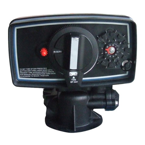
Canature BNT95 Series User manual

TableofContents
Introduction………………………………………………………………………………………………...1
Main Functions…………………………………………………………………………………………….1
Specifications……………………………………………………………...………………………………2
Programming………………………………………………………………………………………………3
1.Button Definition…………………………………...…………………………………………..3
2.Setting Methods………………………………………………………………………………….3
3.Inquiry Function………………………………………………………………………………….3
4.System Initialization……………………………………………………………………………..4
5.Menu Diagram at Different Regeneration Modes……………………………………………5
6.Default Settings………………………………………………………………………………….7
Manual Regeneration…………………………………………………………………………………….7
Water Hardness Adjustment (Optional for Softener Valve)……………………………………..……7
Optional Parts……………………………………………………………………………………………..8
1. Inlet/Outlet Screw Standards……………………………………………………………………..8
2. Inlet/Outlet Screw Adaptor (Optional)……………………………………………………………8
3. Inlet/Outlet Connections Types…………………………………………………………..……….9
4. Drain Line Flow Controls (DLFC) and Injector…………………………………………………10
5. Bypass Assembly…………………………………………………………………..……………..11
Valve Powerhead Assembly…………………………………………………………………………..12
Valve Body Assembly……………………………………………………………………………………14
Bypass Assembly…………………………………………………………………………………….….17
General Valve Installation……………………………………………………………………………….19
Trouble Shooting……………………………………………………………………………………...…20

BNT95SeriesValveOperationManual
-1-
Introduction
This valve is controlled with simple, user-friendly electronics displayed on a large LCD
screen. The main page displays the current time, last regeneration date and regeneration mode.
In addition, the main page also shows key valve information including: volume remaining, flow
rate (meter mode); regeneration days remaining (timer mode).
BNT95 Series Outline
BNT95 Button Pad
MainFunctions
●Valve Operation Mode:
1. SOFTENER: Standard water softener operation.
2. FILTER: Automatic backwashing filters such as Multi-Media Depth or Carbon
Filter.
●Regeneration Mode:
1. Calendar Clock 2. METER IMMEDIATE 3. METER DELAYED
4. Meter Override
●Holiday Mode:
Holiday Mode is available to keep media fresh during the holiday.
●Display Format:

BNT95SeriesValveOperationManual
-2-
Metric format and US format are available to meet the different customers’ requirements.
●Multi-Language Function:
Chinese, English and Spanish are available to meet the different country.
●Smart Controller:
Regeneration Capacity,Regeneration Days and Refill Time can be calculated.
●Auto-locking:
All buttons will be locked after 3 minutes during the stand-by status. Press and hold
“MENU” button for 3 seconds to unlock.
Specifications
●Hydrostatic Test Pressure ………....350 psi (24.15 bar)
●Working Pressure…………………...20~125 psi (1.38~8.62 bar)
●Working Temperature……………….1℃~39℃
●Riser Pipe Diameter Required……..1.05″OD (with 2.5″Valve Base)
2″OD (with 4″Valve Base)
●Electrical Adapter……………………Input: AC110V/AC240V,50Hz/60Hz; Output: AC12V
●Pressure Tank Thread………..……..2.5″NPSM or 4″NPSM
●Inlet/Outlet Connector……………....1.5″
BNT95 (with 4″Valve Base) Dimensional Drawing (unit: inch, mm in brackets)
BNT95 (with 2.5″Valve Base) Dimensional Drawing (unit: inch, mm in brackets)

BNT95SeriesValveOperationManual
-3-
Programming
1.Button Definition:
“MENU”button:
●Enter or exit the system menu.
●Press and hold the button for 3 seconds to unlock the screen.
“SET/REGEN.”button:
●Press this button to select a program or to save the settings.
●Press and hold the button for 3 seconds to initiate a manual regeneration at standby
status.
“/+” and “ /-” button:
●Press the button to increase or decrease the value of the settings.
●Press the button to enter the previous or the next menu.
2.Setting Methods:
●Press the“MENU”button to enter and exit the menu.
●Press the “ /+” or “ /-” button to select a parameter.
●Press the“SET/REGEN.”button, the parameter starts flashing.
●Press the “ /+” or “ /-” button to change the value.
●Press the “SET/REGEN.” button to save the setting.
●Press the “ /+” or “ /-” button to select other parameters.
●Follow the above steps to change other parameters.
●Press the“MENU”button to exit settings.
You can only change the flashing parameters
Program will be back to standby status if any button was not operated in 3 minutes. Without
being operated in 3 minutes, the buttons will be locked.
3.Standby Display:
When power is first supplied, the valve may take up to two minutes to initialize. During this
time, the valve will show:
Do not touch any buttons at this time. When the valve reaches the service position, it will
display:

BNT95SeriesValveOperationManual
-4-
Calendar Clock Mode Meter Mode (Meter Immediate, Meter Delay,
MeterOverride)
Screen shows Current Time, Last Regeneration day, Regeneration Mode, the Remaining
Days of next regeneration, the Capacity Remaining of next regeneration and current Flow Rate.
Numbers of blue bar represent the Remaining Days at Calendar Clock mode.
Numbers of blue bar represent the Capacity Remaining, the Flow Rate at Meter Mode.
Screen will be locked if any button without being operated at the standby display.
4.System Initialization:
When power is first supplied, the valve may take about two minutes to initialize, and the valve
will show:

BNT95SeriesValveOperationManual
-5-
Any button will be overridden at this time. When the valve reaches the service position, it will
return to standby display.
5.Manual Regeneration:
Press and hold the “SET/REGEN.” button for 3 seconds to initiate a manual regeneration, and
screen will display:
When the valve reaches “Backwash” position, screen will display:
When Backwash Remaining time reaches zero or any button is operated, valve will be
advanced to next cycle position: Brine, and screen will display:

BNT95SeriesValveOperationManual
-6-
When the valve reaches “Brine” position, screen will display:
When Brine Remaining time reaches zero or any button is operated, valve will be advanced to
the rest of cycle position: Rinse and Refill, just like the above cycles.
Filter Valve only have two cycles: Backwash and Rinse
6.Main Program:
Press “MENU” button at standby status, it will display the main page:
Press the “ /+” or “ /-” button to move the cursor to the desired setting item. Press the
“SET/REGEN.” button to enter the setting item.
·Current date and current time setting
Current date and current time can be set in “Time” setting item. Setting method:
Press the “ /+” or “ /-” button to move the cursor to the desired parameter.
Press the “SET/REGEN.” button to let the parameter flashing.
Press the “ /+” or “ /-” button to change the value.
Press the “SET/REGEN.” button to confirm and save the setting, parameter stop flashing.
Press the “ /+” or “ /-” button to move the cursor to other desired parameters.
Follow the above steps to change other parameters.

BNT95SeriesValveOperationManual
-7-
Press the“MENU”button to “Time” setting item.
You can only change the flashing parameters.
·Region setting
Unit format can be selected in “Region” setting item. Setting method:
Press the “ /+” or “ /-” button to move the cursor to the desired parameter.
Press the “SET/REGEN.” button to confirm and save the setting, and display returns to
main page.
·Language setting
Language can be selected in “Language” setting item.
Setting method is as the “Region” item setting.

BNT95SeriesValveOperationManual
-8-
·Holiday Mode setting
Holiday Mode can be selected in “Holiday Mode” setting item. You should input the end
of date of holiday to let the valve clean the media during your holiday.
Once you turn on the “Holiday Mode”, the valve’s regeneration only has two cycles:
Backwash and Rinse. “Advanced Settings”is as the follows:
Regeneration Days, Backwash duration and Rinse duration can be set to control
regeneration cycles of holiday.
·Advanced Settings

BNT95SeriesValveOperationManual
-9-
Automatic Calculate mode and Manual Settings mode can be selected in the “Advanced
Settings” item. The key regeneration parameters (Capacity, Refill Time, etc.) can be
calculated in the “Automatic Calculate” mode.
Automatic Calculate mode’s page under different regeneration mode is as follows:
CalendarClock MeterImmediate
MeterDelayed MeterOverride
Manual Settings mode’s page under different regeneration mode is as follows:

BNT95SeriesValveOperationManual
-10-
CalendarClock MeterImmediate
MeterDelayed MeterOverride
‥Regen. Mode
Four Regeneration modes can be selected to meet different installation environment.
Calendar Clock: the unit will initiate regeneration at the next pre-set regeneration time
based on the interval of days between regeneration days.
Meter Immediate: the unit will initiate regeneration immediately after the volume
remaining reaches zero.
Meter Delayed: this is the most common setting. When the volume remaining reaches
zero, the system will initiate regeneration at the next preset regeneration time.
Meter Override: when the volume remaining reaches zero, the system will initiate
regeneration at the next pre-set regeneration time. If the days between regeneration are
reached before the volume remaining reaches zero, the system will override the meter

BNT95SeriesValveOperationManual
-11-
setting and initiate regeneration.
‥Regen. Time
This setting controls the time of day when regeneration will start.
‥Regen. Days
This value is the interval (days) between regenerations. It is used to determine how
many days between regenerations
‥Water Usage
This setting is used to calculate the interval days between regenerations. Monthly
Water Usage is the water usage of average of months

BNT95SeriesValveOperationManual
-12-
‥Water Capacity
This value is the total capacity between regenerations. It is used to determine how
many gallons can be used between regenerations
‥Data Entry
This setting is used to calculate the key regeneration parameters (Capacity, Refill
Time, etc.). These data should be input correctly, wrong data will cause the unit doesn’t
work properly.
‥Regen. Cycle
Backwash time controls the length of time for the unit to clean the bed by reversing the
flow of water upwards through the bed and out to the drain.
Brine time controls the length of time for the unit to draw regeneration (brine for
softeners) from the brine tank and slowly rinse the media tank from the top to the bottom.
Rinse time controls the length of time to give the tank a final rinse from the top to the
bottom in order to remove any last traces of the regeneration from the tank.
Refill time controls the length of time which the brine valve will open to refill the brine
tank with water in order to produce the regeneration solution for the next regeneration.
The water accurately measured through the valves brine line flow control to make a
precise quantity of regeneration solution.
Filter Valve only have two cycles: Backwash and Rinse

BNT95SeriesValveOperationManual
-13-
Refill time is calculated under Automatic Calculate mode
‥Restore Defaults
This setting allows the current settings to be erased and changed back to the default
settings.
·System Information
Press the “ /+” or “ /-” button to inquire some information of valve by entering “System
Information” item.

BNT95SeriesValveOperationManual
-14-
In “Total Regenerations” and “Peak Flow Rate” page, press and hold “SET/REGEN.”
button for 3 seconds can reset the value to zero.

BNT95SeriesValveOperationManual
-15-
RemovingControllerAssembly
Manually removing the Controller Assembly:
• Press and hold Manual Button
• With 8 hex key, insert Cam Hole, turn the Cam anti-clockwise to the marked position
• Remove the Connector
• Remove the Locking Bar
• Pull outward the Controller Assembly
Automatic removing the Controller Assembly:
• Unlock the screen
• Press and hold “ /-” button, the valve will advance the Cam to the marked position
• Remove the Connector
• Remove the Locking Bar
• Pull outward the Controller Assembly

BNT95SeriesValveOperationManual
-16-
Replacing Drain Line Flow Control and Brine Line Flow Control
To replace the Drain Line Flow Control (DLFC):
• Remove the Clip
• Pull the Drainlet outward
• Pull the DLFC Holder outward from the Drainlet
• Replace the DLFC
To replace the Brain Line Flow Control (BLFC):
• Remove the Clip
• Pull the Brinelet outward
• Pull the BLFC Holder outward from the Brinelet
• Replace the BLFC

BNT95SeriesValveOperationManual
-17-
Replacing Injectors
To replace the Injectors:
• Remove the Connector
• Remove the Screw
• Slightly pull the Injector Body and Injector Cover outward
• Slightly pull out the Screen
• Replace the Nozzle
• Slightly pull out the Air Disperser
• Replace the Throat
Injectors, DLFC and BLFC’s Suggest Configuration with Tanks
Softener Filter
10 1 1 01 03
12 2 1 02 1
14 5 1 03 2
16 6 2 1 3
18 6 2 2 4
21 7 3 3 5
24 7 3 4 6
Tank Size
(inch) BLFC DLFC
Injector

BNT95SeriesValveOperationManual
-18-
Valve Powerhead Assembly
Bnt95 Powerhead Assembly Parts List
Item No. Part No. Part Description Quantity
A01 05040038 Bnt95 Cable Jaket(without hole) 2
A02 26010028 O-Ring-Ø28×2.65 1
A03 05040086 O-Ring-Ø8×2 2
A04 05040005 Bnt95 Housing 1
A05 05040008 Bnt95 Driving Cam 1
A06 05040032 O-Ring-Ø4×1.5 1
A07 05040009 Bnt95 Driven Cam 1
A08 05010078 Magnet-Ø4x3 1
A09 05040095 Bnt95 Brine Valve Connector 1
A10 05056085 Screw-ST2.9×10(Large Wafer) 7
A11 05040052 Bnt95 Sensor Pcb 1
A12 05010047 Friction Point 6
A13 05040007 Bnt95 Mounting Plate 1
A14 05056084 Screw-ST3.5×13 10
A15 05056129 O-Ring-Ø23×3 1
A16 05040054 Bnt95 Meter Cable 1
05040039 Bnt95 Meter Cover 1
05040037 Bnt95 Cable Jaket(with hole) 1
05040086 O-Ring-Ø8×2 1
A17 05040053 Bnt95 Power Cable 1
05040037 Bnt95 Cable Jaket(with hole) 1
05040086 O-Ring-Ø8×2 1
A18 05040087 O-Ring-Ø5.5×1.5 4

BNT95SeriesValveOperationManual
-19-
A19 05040044 Bnt95 Motor Pin 1
A20 05040047 Bnt95 Motor (AC12V,2RPM) 1
A21 05040046 Bnt95 Gear Spring 1
A22 05040040 Bnt95 Gear 1
A23 05040033 Bnt95 Piston Rod Bush 1
A24 05040041 Bnt95 Manual Button 1
A25 05040085 O-Ring-Ø10×2.5 1
A26 05040051 Bnt95 Main PCB 1
A27 05056529 Bnt465 Button 4
A28 05040043 Bnt95 Housing Seal 1
A29 05040036 Bnt95 Clear Cover 1
A30 05040006 Bnt95 Cover 1
A31 05040092 Bnt95 Label (Filter) 1
05040093 Bnt95 Label (Softener) 1
A32 05040026 Bnt95 Brine Valve Piston Rod 1
Table of contents
Other Canature Control Unit manuals
Popular Control Unit manuals by other brands

Kemper
Kemper MULTI-FIX-PLUS 150 6G Installation and operating instructions

Honeywell
Honeywell ST7700 quick start guide

WAGO
WAGO 750-429/040-001 manual

Jaycar
Jaycar Maycar Electronic Dice Kit quick guide

Great River Technology
Great River Technology ARINC 818 HS SAM Gen II quick start guide

Videx
Videx 4842 Installation instruction

JP Fluid Control
JP Fluid Control BW Series manual

pumpa
pumpa PPC22-2P Translation of the original instruction manual

ON Semiconductor
ON Semiconductor LV8702VSLDGEVK quick start guide

Trane
Trane Tracer MP503 Installation and operation

horsch
horsch DrillManager ME operating instructions

Redback
Redback A 2073 operating instructions