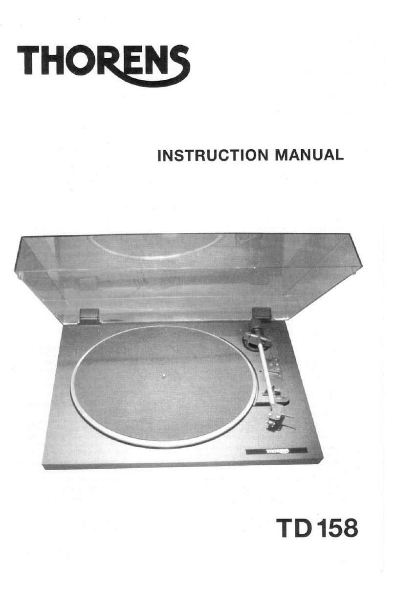
THORENS TD 240-2 User manual


THO
/
BEDIENUNGSANLEITUNG
OPERATING INSTRUCTIONS
NOTICE D'EMPLOI
1
TD
240-2

2
In
ha
It
Auspacken und Montage
Elektrische Anschli.isse und Aufstellung
Tonarm und Tonabnehmersystem
Montage und Justierung des Tonabnehmers
Bedienung des TD 240-2
Justierung des Tonarmaufsetzpunktes
Technische Oaten
Contents
Unpacking and assembly
Electrical connections and installation
Tone arm and pickup cartridge
Vertical alignment
of
cartridge
Operation
of
the TD 240-2
Adjustment
of
tone arm set-down point
Technical specification
Table
des
matieres
4
4
6
8
10
10
12
5
5
7
9
11
11
13
Deballage etassemblage 5
Connexions electriques et installation 5
Bras etcellules de lecture 7
Montage et reglage de
la
cellule de lecture 9
Mode d'emploi de
la
TD 240-2
11
Reglage du pointdedescente du bras de lecture
11
Donnees techniques 14
Sehr geehrterThorens-Kunde,
herzlichen Dank fur
1hr
Vertrauen
in
unser Produkt, den
Plattenspieler
TD
240-2. Mil dem Kauf dieses Plattenspielers
haben Sie ein Prazisionsinstrument
zur
Wiedergabe von
Schallplatten erworben, das, um seiner Aufgabe gerechl zu
werden, mil Sorgfall behandell und aufgestellt werden muss.
Die Fertigung dieses Laufwerks und die Montage erfolgen
komplett
in
Deutschland -dies garantiert hochste Qualital,
auch noch nach Jahren.
Verstandlicherweise wollen Sie moglichst sofort mit dem
Musikhoren loslegen. Wir bitten Sie jedoch: Lesen Sie diese
Anleitung vor dem ersten Gebrauch aufmerksam durch,
damil Sie das Laufwerk optimal nutzen konnen und lange
daran Freude haben.
Wir haben uns bemi.iht, alles Notwendige und Wissenswerte
in
dieser Anleitung unterzubringen. Sollten Sie noch Fragen
haben, die hier nichl beantworlel werden, so wenden Sie
sich direkt an lhren Handler.
1hr
Thorens-Team
Warnung!
Um Brandgefahr oder elektrischen Schaden
vorzubeugen,
darf
das Gerat nicht Feuchtigkeit oder
Regen ausgesetzt werden.

DearTHORENS customer,
Thank you very much
for
your confidence
in
our prod-
uct, the record player
TD
240-2. With the purchase
of
this device you have acquired a precision instrument
for the purpose
of
playing back analogue records.
This appliance however requires your attention with
respect to set-up, placement and handling in order to
achieve a flawless operation. The TD 240-2 has been
designed and assembled completely
in
Germany
which will guarantee you the highest quality to be
maintained
for
years to come. Understandably, you
want to listen to your beloved records right away but
we strongly advise that you read these instructions
attentively before proceeding with the setup, simply to
ensure long-lasting listening pleasure. We have
spared no efforts
to
pack all necessary information
and comprehensive guidance into this manual, yet in
the event that you have any further queries regarding
your new record player please do not hesitate to ask
yourTHORENS dealer
for
further assistance.
Sincerely yours,
THORENS TEAM
WARNING!
To prevent fire
or
shock hazard, do not expose
this product rain
or
moisture.
Cherclient THORENS,
merci d'accorder votre confiance a noire produit,
la
platine TD 240-2. Avec !'acquisition de cette platine,
vous disposez d'un instrument de precision pour
la
reproduction de disques, qui doit etre manipule et ins-
talle avec soin, pour qu'il puisse repondre avos atten-
tes. La fabrication et !'assemblage de cette platine
TD 240-2 sont entierement realises en Allemagne -
ce qui est une garantie de qualite superieure, meme
apres de longues annees d'utilisation.
Bien entendu, vous souhaiteriez ecouter immediate-
ment de
la
musique. Cependant nous vous recom-
mandons de lire attentivement ce mode d'emploi
avant toute mise en service, afin de pouvoir utiliser
de
fac;:on
optimale cette platine et d'en profiter
le
plus
longtemps possible. Nous nous sommes efforces
d'inclure dans cette notice les instructions indispen-
sables et tout ce qu'
il
est bon de savoir pour une utili-
sation conforme. Pour toute autre question, veuillez
vous adresser directement avotre revendeur.
Votre equipe Thorens
AVERTISSEMENT!
Afin d'eviter tout risque d'incendie ou d'electrocution,
ne pas exposer l'appareil ala pluie ou al'humidite.
3

Auspacken und Montage
Entnehmen Sie
das
Gerat und alle Zubehorteile
der
Ver-
packung.
Entfernen Sie durch seitlichen Druck die beiden Transport-
sicherungen (Fig.1). Sie befinden sich vorne links und hinten
rechts unter dem Plattenteller.
Legen Sie nun den Plattenteller auf den Antriebsteller und
drucken die beiden Sicherungsfedern soweit nach unten, bis
sie in die Rille
der
Plattentellerachse einrasten (Fig.
2)
.
Stecken Sie die beiden Scharniere in die dafur vorgesehenen
Aussparungen (Fig.
3).
Schieben Sie die Abdeckhaube parallel zu
der
Stellung der
Scharniere(Offnungswinkel ca.
60
°) biszum Anschlag in diese
ein.
In
dieser Stellung laBt sich die Haube auch jederzeit wie-
der abnehmen.
Elektrische Anschlusse
Durch die Auswahl eines entsprechenden THORENS-Netz-
transformatorskann derPlattenspieleran alien vorkommenden
Netzwechselspannungen betrieben werden. Der Niederspan-
..:.mgssteckeram Kabel des Steckernetztransformatorswird in
die Buchse 17 (Fig.
4)
an
der
Gerateruckseitegesteckt.
Das Stereo-Verbindungskabel besitzt zwei Phonostecker (von
manchen Herstellern auch Cinch-Stecker oder RCA-Stecker
genannt). Sie sind entweder mit L fur den linken Kanai und R
fur
den rechten Kanai bezeichnet. Fehlen dieseBuchstaben,
so
istderrechteKanai mit
rotund
derlinkeKanai mitweiBgekenn-
zeichnet.
Die Cinch-Stecker werden in die Phono-Buchsen am Verstar-
ker oderReceiver gesteckt.
Die getrennt gefuhrte Litze stellt die Erd- oder Masseverbin-
dung her. Sie wird unter die Masseschraube des Verstarkers
geklemmt.
WICHTIG !
BEWAHREN SIE DIE GERATEVERPACKUNG AUF,
FALLS DAS
GER.A.T
ZUM
TRANSPORT VERPACKT
WERDEN MUSS.
4
Fig.1
Fig.2
Fig.3
17
Fig.4

Unpacking and set-up
Take
the record player and all accessories out
of
the carton.
Remove the two transportation locks (Fig.
1)
by applying
lateral pressure. The locks are located underneath the platter
at the front left and at the rear right.
Put the platter onto the sub-platter and press down the two
safety springs until they set into the groove
of
the platter
spindle
(Fig
.
2)
.
Insert each hinge into the respective recess (Fig.
3).
Hold the dust cover parallel
to
the hinges (opening angle
approximately
S0
°), insert and push as far
as
it will go. Being
in
this position the dust cover may
be
removed
at
any time.
Electrical connections
By choosing the appropriate THORENS mains transformer
this record player can be operated from nearly all existing
public mains supplies. The low-voltage plug on the cable that
is coming from the mains transformer unit is
to
be inserted
into jack 17
(Fig.
4)
at the rear side
of
the
record player.
The stereo signal leads have
two
phono plugs which are also
known as "Cinch" or RCA-plugs. They are marked with either
the letter "L"
for
the left channel or "R" for the right channel.
If these letters are missing then most likely the right channel
is marked red, perhaps
by
featuring a red plug at both ends,
and the left channel is marked white
or
black accordingly. The
RCA-plugs are inserted into the phono input jacks
of
an
amplifier
or
receiver. The separate single litz-wire is making a
connection
to
ground and is
to
be fastened underneath the
ground screw
of
the amplifier
or
receiver.
IMPORTANT!
ALWAYS KEEP THE SHIPPING CARTON
IN
A DRY
PLACE FOR THE EVENT THAT THE RECORD
PLAYER HAS
TO
BE PACKED AGAIN FOR TRANS-
PORTATION.
Deballage et assemblage
Retirez l'appareil ainsi que toutes les pieces accessoires du
carton d'emballage.
Enlevez les deux butees
de
transport
en
les poussant laterale-
ment (fig.
1).
Elles se trouvent a l'avant gauche et a l'arriere
droit sous le plateau du tourne-disque.
Posez maintenant le plateau sur la plaque support du moteur
et poussez les deux ressorts d'arret vers l'arriere jusqu'a ce
qu'ils s'encliquettent dans !'orifice de l'axe du plateau (fig.
2).
Enfoncez les deux charnieres dans les ouvertures prevues a
cet effet (fig.
3).
Placez le couvercle paralellement aux charnieres (angle d'ou-
verture env.
S0
°) jusqu'a ce qu'il soit bloque dans celles-ci.
Ainsi, le couvercle peut etre enleve a tout moment.
Branchements
L'utilisation d'un transformateur d'alimentation THORENS
correspondant vous permet de connecter le tourne-disque a
toutes les tensions alternatives existantes.
La
fiche basse
tension du cable transformateur d'alimentation doit etre
enfoncee dans la prise 17 (fig.
4)
a l'arriere de l'appareil.
Le cordon
de
raccordement stereo possede deux fiches
"phono (aussi appelees fiches Cinch ou fiches RCA par cer-
tains fabricants). Elles sont, soit marquees d'un L pour le
canal gauche, soit d'un R pourle canal droit. A defaut
de
ces
lettres, lecanal droitest en rouge et le canal gauche en blanc.
Les fiches Cinch doivent etre enfoncees dans les prises
phono
de
l'amplificateur
ou
du recepteur.
Le
cordon livre separement assure la connexion al la masse
ou
a la terre. Veuillez
le
coincer sous
la
borne
de
masse
de
l'amplificateur.
IMPORTANT!
CONSERVEZ LE
CARTON
D'EMBALLAGE
AU
CAS
OU VOUS DEVRIEZ
REMBALLEWR
L'APPAREIL
POUR LE
TRANSPORT.
5

Tonarm- und Systemeinstellungen
Stellen Sie den Regler fur die Auflagekraft
(1)
auf 0 und
drehen Sie die Antiskating-Einrichtung
(2)
entgegen
dem
Uhrzeigersinn bis
an
den Anschlag
(Fig
.
6)
.
Nun drehen Sie das Tonarm-Gegengewicht
(3)
auf das
hintere Tonarmrohr (Fig.
5)
.
Entriegeln Sie den Tonarm
(4)
und schwenken ihn nach
innen. Bringen Sie den Lifthebel
(5)
in Stellung
.,,.
, dabei
den Tonarm festhalten (Fig.
6).
Durch Verdrehen des Gegengewichts
(3)
kann
der
Tonarm
exakt ausbalanciert werden; er muss frei schweben.
Legen Sie den Arm zurUck
in
die Tonarmstutze. Nun
konnen Sie die Auflagekraft
(1)
und die Antiskatingkraft
(2)
einstellen. Bei dem eingebauten
TAS
267 werden
15
mN
eingestellt.
Beachten sie die nachstehende Tabelle:
Auflagekraft
(1)
Antiskatingkraft
(2)
1 = 10 mN 1
1,25 = 12,51; mN 1,25
1,5 = 15 mN 1,5
2 = 20 mN 2
2,5 = 25 mN 2,5
3 = 30 mN 3
6
Fig. 5
3
2
5
Fig. 6

Adjusting tone arm and pick-up cartridge
Turn thetracking force adjuster
(1)
to
.,O"
and theanti-skating
knob
(2)
counter-clockwise until it stops (Fig.
6).
Screw thetonearm counter weight
(3)
onto
thereartone arm
tube (Fig.
5).
Unlock
the
tone arm
(4)
and move it a
bit
towards thecentre
of
theplatter. Bringthe lift-lever
(5)
intoposition
DOWN
while
holding back
the
tone arm (Fig.
6).
Byturning
the
counterweight
(3)
thetone arm can be preci-
sely balanced
in
order
to
make
it
hoverfreely above the plat-
ter.
Movethetonearm backtoitsrest.
You
can nowadjustthe
tracking force
(1)
and the anti-skating force
(2).
Adjust
to
1.5
mN (Milli-Newton)
for
the
factory-installed pick-up cartridge
TAS
267.
As
forthe required anti-skating forcerefertothetable
below:
Scale
Tracking
force
Anti-skating
force
1 =
10
mN
1
1,25 = 12,5
mN
1,25
1,5 = 15
mN
1,5
2 =
20
mN
2
2,5 = 25
mN
2,5
3 =
30
mN
3
Reglages du bras
de
lecture et du systeme
Amenez le bouton
de
reglage
de
la force d'appui
(1)
surO
et
tournez le bouton
de
reglage
de
l'antiskating
(2)
dans le sens
inversedesaiguilles d'unemontrejusqu'au blocagecomplet
(Fig.
6).
Vissez maintenant le contrepoids
du
bras
(3)
sur l'extremite
arriere
du
bras
de
lecture (Fig.
5).
Deverrouillez le bras
de
lecture
(4)
et
deplacez-le vers
l'interieur. Actionnez le levier
du
lave-bras en tenant le bras
de
lecture (Fig.
6).
En
tournant le contrepoids
(3),
vous pouvez exactement
equilibrer le bras,
ce
dernier
doit
se mouvoir librement.
Ramenez lebras surlerepose-bras, Maintenant, vouspouvez
regler la valeur
de
la force d'appui
(1)
et
de
l'antiskating
(2).
Pour le systeme
TAS
267 integre, ii est recommande
de
regler
la valeur a15 mN.
Veuillez tenir compte
du
tableau suivant:
Grad.
Force
d'appui
Valeur
de
l'antiskating
1 =
10
mN
1
1,25 12,5
mN
1,25
1,5 = 15
mN
1,5
2 = 20
mN
2
2,5 = 25
mN
2,5
3 =
30
mN
3
7

Montage und Justierung
des
Tonabnehmersystems
Wechsel des Tonabnehmersystems
Ziehen Sie zuerst die Anschlussleitungen am System vor-
sichtig mit einer Pinzette ab. Entfernen Sie die beiden Be-
festigungsschrauben und nehmen Sie das System ab.
Das neueSystem zuerst nurleicht anschrauben und dieAn-
schlussleitungen wieder
auf
die Anschlussstifte stecken,
dabei die Farbkodierung beachten.
Anstelleeines eingebautenTonabnehmers kann ein anderer
1/2 Zoll-Tonabnehmer
mit
einem Eigengewicht von 3 -
10
g
eingebaut werden.
Ziehen SiedieAnschlussleitungen am System vorsichtig mit
einer Pinzette ab. Losen Sie
die
konische Mutter
(9)
hinter
dem Systemtrager. Ziehen Sie nun den Systemtrager vor-
sichtig uber
die
Anschlussleitungen nach vorne ab (Fig.
7).
Danach den neuen Systemtrager in umgekehrter Reihen-
folge wieder montieren. Achten Sie
auf
die Farbkodierung
R =
RG
=
L =
LG
=
Rot, rechter Kanai
Grun, rechter Kanai Masse
WeiB,
linker Kanai
Blau, linker Kanai Masse
Das Anschlussbeispiel in Fig. 8 gilt fur
das
System
AT
95
B!
Justierung nach Tonabnehmerwechsel
Schieben Sie die beiliegende Montagelehre in den System-
trager. Die Montage ist korrekt, wenn die Abtastnadel, von
oben betrachtet, in derV-formigenAussparung derSystem-
einbaulehre steht.
Von
derSeite betrachtet, muss die Nadel
im Bereich der rechteckigen Aussparung stehen (Fig.
9).
Stecken Sie den Systemtrager wieder auf
das
Tonarmrohr
und schrauben die Mutter
(9)
fest.
ACHTUNG!
Seien Sie bei diesem Vorgang sehr vorsichtig, damit nicht
durch unabsichtliche Bewegung dieAbtastnadel beschadigt
wird.
Nach Beendigung der Systemmontage mussen die Befesti-
gungsschrauben festgezogen werden.
Abtastnadeltausch
Die Abtastnadel ist durch den Abspielvorgang naturlichem
VerschleiB ausgesetzt. Wir empfehlen daher eine regelma-
Bige Oberprufung der Diamantabtastnadel nach
ca
. 500
Spielstunden.
Abgenutzte oder beschadigte Abtastnadeln beschadigen
lhre Schallplatten!
8
Fig. 7
L RG
we
11}
grun
\I""~--,-----,.
...
LG
Fig. 8
R = Rot rechter
Kanai
RG
=
Grun
rechter
Kanai
Masse
L =
WeiB
linker
Kanai
LG
=
Blau
linker
Kanai
Masse
Fig. 9

Mounting
or
exchanging a pick-up car-
tridge system
Change
of
cartridge system
Remove thecoloured signal leads carefully from the
cartridge pins with a pair
of
tweezers. Unscrew the
cartridge. Screw
the
new cartridge onto the head
shell but
do
nottighten. Attach the leads
to
the pins
while observing
the
correct coding.
Instead
of
the factory-supplied pick-up cartridge
any other cartridge with standard half-inch mount-
ing holesand a weight between 3 and 1Ograms can
be installed.
Removethecoloured signal leads carefully from the
cartridge pins with a pair
of
tweezers. Loosen the
collar-lock
(9)
behind
the
head shell. Carefully pull
the coloured signal leads out
of
the head shell. (Fig.
7).
Install the head shell in reverse order.
Pay attention to the correct colourcoding
R
RG
L
LG
=
=
=
=
Red, right channel
Green, right channel ground
White, left channel
Blue, left channel ground
Please note: The example shown in Fig. 8 is appli-
cable only for the pick-up cartridge
AT
95 B!
Adjusting after change of pick-up
cartridge system
For the precise adjustment
of
the so-called stylus
overhang push
the
supplied mounting gauge into
the head shell with cartridge. The adjustment
is
cor-
rect ifthestylus is flush with the V-shaped recess
in
the gaugeasviewed from above. When viewed from
the sidethestylus should be seen within the rectan-
gular recess
of
the gauge (Fig.
9).
Adjust the car-
tridge
in
the head shell untilthecorrect positions are
achieved. Lastly, tighten the mounting screws, put
the head shell with cartridge back
on
the tone arm
and tighten the collar-lock
(9).
ATTENTION!
During these mounting and adjustment procedures
you must be verycareful
not
to
damagethe delicate
stylus and cantilever
by
uncontrolled and brisk
movements.
Replacing the stylus
Any stylus is subject
to
wear even under normal
playing conditions. Therefore, it is highly recom-
mended
to
have the cartridge, respectively its sty-
lus, inspected afterabout500 hours
of
playing. This
is because a worn
or
damaged stylus will eventually
damage your precious vinyl records!
Remplacement / montage
de
la cellule
de
lecture
Changement
de
la cellule de lecture
Enlevez avec precaution les cordons
de
raccorde-
ment
de
la cellule al'aide d'une pincette. Retirez les
deux vis de blocage. Pour
le
moment vissez legere-
ment
la
nouvelle cellule et enfoncez les cordons
de
raccordement dans les prises
en
faisant attention aux
codes couleur.
Vous pouvezinstaller a
la
place delacellule de lecture
fournie avec l'appareil une autre cellule
de
lecture
d'un
demi pouce et
de
3 - 10 g.
Enlevez avec precaution les cordons
de
raccorde-
ment
de
la cellule al'aide d'une pincette. Desserrez
l'ecrou conique
(9)
qui se trouve derriere le support
de
systeme. Tirez le support sur les cordons
de
rac-
cordement doucementvers l'avant(fig.7). Par la suite,
le
support de system est monte dans l'ordre inverse,
en faisant attention aux codes couleur:
R = Rouge, canal droit
RG
= Vert, canal droit, masse
L = Blanc, canal gauche
LG
= Bleu, canal gauche, masse
L'exemple
de
branchement indique dans la figure 8
se rapporte
au
systeme Ortofon
AT
95
B!
Ajustement apres changer la cellule
de
lecture
lnserez la glissiere de montage fournie dans le sup-
port
de systeme Le montage est correct lorsque la
pointe de lecture,vued'en haut, est placee dans l'ou-
verture en V de la glissiere de montage.
Vue
de
cote,
la pointe
doit
etre enfoncees dans !'orifice rectangu-
laire (fig.
9)
.
Enfichez le support de systeme dans la tige du bras
de lecture
et
revissez l'ecrou
(9).
ATTENTION!
Faites attention ane pas endommager
le
pointe de
lecture
de
cette operation.
Apres avoir monte la cellule de lecture,resserrez les
vis
de
blocage.
Remplacement
de
la pointe
de
lecture
La pointe
de
lecture se deteriore a l'usage. C'est
Pourquoi ii est recommande de controler reguliere-
ment la pointe apres environ 500 heures d'utilisation.
L'utilisation de pointes usees ou abimees peut en-
dommagervos disques.
9

Drehzahlwahl
Mit dem linken Schaltknopf lassen sich die Ge-
schwindigkeiten 33, 45 und 78 einstellen (Fig. 10).
Plattendurchmesserwahl
Mit dem Schalter (6) rechts neben dem Tonarm kann
der Plattendurchmesser auf17 cm (Single)
und
30
cm
(LP
)
eingestellt werden. Dies ist nur bei automatischem
Start notwendig (Fig. 11)
Justierung des Tonarmaufsetzpunktes
DerTonarmaufsetzpunkt ist vom Werk aus richtig Fig 10
eingestellt. Bei Abweichungen drehen Sie die Justier-
schraube (8) entsprechend nach rechts oder links, bis
die Abtastnadel einwandfrei in der Einlaufrille auf-
setzt.
Automatischer Start
Ziehen Sie den durchsichtigen Nadelschutz nach vor-
ne ab.
Der Lifthebel (5) muss sich
in
der Stellung
:!f':
befinden.
Schieben Sie den Schalthebel (7)
auf
Start und der
Tonarm setzt automatisch
auf
der
Schallplatte
auf
.
(Fig.11)
Manueller Start und Tonarmlift
Bringen Sie den Lifthebel (5)
in
Stellung
!'.
.
Nehmen Sie den Tonarm von der Tonarmstotze und
schwenken ihn
Ober
die Einlaufrille der Schallplatte.
Der Motor lauft jetzt an. Der Tonarm wird nun mit dem
Lifthebel (5) bedampft und Platten schonend abge-
senkt
:!f':
.
Mit dem Lifthebel kann der Tonarm
an
jeder beliebigen
Stelle, auch zur kurzzeitigen Spielunterbrechung, ab-
gehoben werden. Der Plattenteller dreht sich weiter.
(Fig.11)
Stop
Am Ende der Schallplatte wird der Tonarm automa-
tisch zur Tonarmstotze zurOckgefOhrt und das Gerat
abgeschaltet. Sie k6nnen den Plattenspieler auch ab-
schalten, indem Sie den Schalthebel (7)
auf
Stop
schalten, oder den Lifthebel (5)
in
Stellung
!'.
bringen
und
den Tonarm von Hand auf die Tonarmstotze zu-
rOckfOhren
. (Fig. 11)
10
Fig.11

Selecting Speed
With the knob on the left the speed can be set at
33, 45 and 78 rpm (Fig. 10)
Selecting record diameter
With the button (6) on the right near the tone arm,
the diameter
of
the records can be pre-set,
whereby 17 cm is used for "Single" and
30
cm for
"Long Play (LP)" vinyl records. This function is
necessary only when the record player is operated
in
its automatic mode (Fig.
11
).
Adjustment oftone arm set-down point
Turn the adjusting screw (8) clockwise until the
pickup needle is lowered accurately into starter
groove.
Automatic start
Remove the transparent stylus guard by carefully
pulling ittowards you.
The lift lever (5) must be in position
::if:
.
Move the knob (7) into position Start and the tone
arm will be automatically lowered onto the record
(Fig.11)
Manual start and tone arm lift
Bring lift-lever (5) into position ! . Unlock the tone
arm from its rest and move it above the lead-in
groove
of
the record. The motor and platter will
now start turning. By lowering the lift-lever (5) the
tone arm gently declines, thus being very kind to
your precious records. With the help
of
the lift-lever
the tone arm may be moved up and down again
anywhere across the record while the platter keeps
turning (Fig. 11)
Stop
After reaching the lead-out groove the tone arm
will be automatically lifted up and returned to its
rest. The motor is switched
off
. You can also
switch
off
the record player by either moving knob
(7) into position
Stop
, or by raising lift-lever (5)
into position ! and returning the tone arm
manually to its rest (Fig. 11)
Selection de vitesse
Le bouton gauche vous permet de regler les vites-
ses 33
Umn
,45
Umn
ou
78
U
mn
(Fig. 10)
Selection de diametre des disques
Le bouton (6) adroite du bras de lecture permet de
regler le diametre des disques (17 cm et 30 cm).
Cette operation est uniquement necessaire pour la
mise en marche automatique (Fig. 11)
Reglage du point de descente du bras de
lecture
Tournez
la
vis de reglage (8) vers
la
droite
ou
vers la
gauche jusqu'a ce que l'aiguille de lecture se pose
exactement dans le sillon d'entree du disque.
Mise en marche automatique
Enlevez
le
protege pointe transparent,
en
le
tirant
vers l'avant. Le levier du leve-bras (5) doit etre
actionne.
Placez le levier de commande en position
START
afin que le bras de lecture se positionne automati-
quement sur le disque (Fig.
11
).
Mise en marche manuelle
et
utilisation du
Ieve-bras
Actionner le levier du leve-bras (5).
Enlevez
le
bras de lecture du repose-bras et placez-
le sur le sillon d'entree du disque. Le moteur
d'entrainement se met
en
marche. Le bras
de
lecture est ralenti
par
le levier du leve-bras (5
),
ensuite ii s'abaisse delicatement sur le disque.
Le levier du leve-bras permet de relever le bras a
n'importe quel point, meme pour des arrets
de
courte duree. Le plateau du tourne-disque continue
de tourner (Fig. 11)
Arret
Lorsque le bras de lecture arrive a l'extremite du
disque, ii revient automatiquement sur
le
repose-
bras, et l'appareil arrete de fonctionner. Vous pou-
vez aussi eteindre le tourne-disque en amenant le
levier de commandement (5) dans la position
STOP
,
ou
en
actionnant le levier du leve-bras et en rame-
nant manuellement le bras sur le repose-bras (Fig.11)
11

Technical
data
Measured values = typical values
Belt drive
electronic-controlled
DC
motor
Mains voltage
(Mains set) 100 -240 V
(AC)
Line frequency 50/60 Hz
Power requirement
1,5W
Platter speeds
33
'h,
45, 78 U/min
Wow and flutter
DIN/WRMS ± 0,07/0,04 %
Platter 304
mm
0
Signal-to-noise ratio
(DIN 45 500)
Rumble unweighted signal-to-noise ratio 48
dB
Rumble weighted signal-to-noise ratio 72
dB
Effective tonearm length 211
mm
Offset angle
26
°
Overhang 1·9,5
mm
Tangential tracking error 0,15°
/cm
Rad.
Cartridge
HiFi DIN 45 500
red R right channel TAS 267
green
RG
right channel ground
blue
GL
left channel ground
white L left channel
Diamond stylus ATN 95 E
elliptical 0,4 X 0,7 mil
Diamond stylus
for
78
U/m1n.
ATN 9578
conical
65
µm
Tracking force
1,5g/mN
Frequency range 20-20000 Hz
Output 3,5
mV/5cms/1
kHz
Tracking capability (315 Hz)
80
µm
Cartridge weight 5,7 g
Total capacitance
Tonearm leads and audio-cables
ca
. 160 pF
Dimensions
(W
x H x D) 430 X 130 X 365
subject to modifications
13

THO
Thorens Services Ltd.
Im
Junkholz 44, CH-4303 Kaiseraugst / Switzerland
Internet: http://www.thorens.ch, Email: [email protected]
Printed in WestGermany •
Druck
Ugi
Lahr

®
Technical Specifications
Issued 4/2016. Specifications are subject to change without prior notice.
© 2016 Thorens Services AG, Switzerland. Further information: www.thorens.com
TD 240-2 Turntable
Operation fully automatic
Drive System internal at drive belt
Motor electronically controlled DC motor
Speeds 33-1/3, 45, 78 rpm
Speed Select electronically
Platter 12” / 0.7 kg (aluminium, non-magnetic)
Tonearm THORENS® TP 19-1
Pick-up Cartridge THORENS® TAS 267
Anti-skating (Bias) by spring (adjustable)
Automatic Shut-off mechanically
Cable Capacitance 160 pF
Power Supply external mains adaptor (115-230 V / 50-60 Hz depending on type)
Dimensions 430 x 130 x 365 mm (W x H x D)
Weight 6.4 kg
Finish solid wooden plinth with black piano laquer, black structured enamel, walnut veneer
Scope of Delivery mains adapter, dust cover (acrylic), RCA interconnects, operating instructions
THORENS.TECH-TD2402-2016-EN/1

Online Produkt Registrierung
THORg!5
®
Anleitung
1.
Rufen Sie die Webseite
www
.thorens.com/registrierung
in
lhrem Browser auf.
2. Wahlen Sie Art und Bezeichnung des Produkts, das Sie
registrieren mochten. Halten Sie bitte die
Seriennummer
und
das Kaufdatum bereit.
3. Geben Sie lhre personlichen Oaten ein.
4. Wahlen Sie, ob Sie aktuelle Nachrichten und lnformationen
von Thorens erhalten mochten.
5. Geben Sie am Ende der Seite den abgebildeten Sicher-
heitscode ein und klicken Sie auf
,,
Registrieren".
6. Sie erhalten im Anschluss eine E-Mail Nachricht mit der
Bestatigung lhrer Registrierung.
Hinweis: Bille beachten Sie unsere Datenschutzbestimmungen, die Sie am
Ende des Registrierungsformulars finden. Die Online Registrierung ist nur tor
Produkte miiglich, die nach dem
31.1
2.
1999 hergestellt wurden.
Online Product Registration
Instructions
1.
Go to the following website: www.thorens.com/register
2.
Select the name
of
the product you wish
to
register. Please
have the serial
number
and the
date
of
purchase at hand.
3. Enter your personal information.
4. Tick the box if
you
wish
to
receive news and other informa-
tion from
us.
5. Enter the security code displayed at the bottom of the page
and click
on
"Register':
6.
You
will then receive
an
e-mail confirming your registration.
Note:Our privacy policy terms and conditions are outlined at
th
e bottom
of the form.Only products manufactured after
31
December 1999 can be
registered online.
THO REG10-ALL 0913
+
f'!
"""'
'
,-
"'
- ·
'°"'
''
.,
.
IU.,
m-
.
THORC.!!S
Product Re
gi
stration
l\•
gic91•
• yo
ur
pro
du
ce
with Tho
r•n
•
Rlgh,l
..
ro--~
-
-Ot~-
......
1o,,...,~----
IIIQII
......
,_
-w11..o,,.,
...
1o,_l"'"".,,ll'IIIINI<..,..,.,..
•NfllC>'
111:,unu,
tlci
••lt~
THORg!S
®
Product Registration
R•ght•ryow
pro
ductwfthThor•n.
-c,
--
~,....
____
..
______
...
_,.,.,._.
____
~
_
_
..
_ _ _ loa>tta:l'lf:Mlfl
..
.....,._.m.ay
....
h:.-..._
Table of contents
Other THORENS Turntable manuals

THORENS
THORENS TP 92 User manual

THORENS
THORENS TD 145 MKII User manual

THORENS
THORENS mini User manual

THORENS
THORENS TD 1600 User manual

THORENS
THORENS TD 524 User manual

THORENS
THORENS TD 165 User manual

THORENS
THORENS TD-150 User manual

THORENS
THORENS TD 158 User manual

THORENS
THORENS TD 102 A User manual

THORENS
THORENS TD 800 series User manual

THORENS
THORENS TP 82 User manual

THORENS
THORENS TD 2001 User manual

THORENS
THORENS TD 190 User manual

THORENS
THORENS TD202 User manual

THORENS
THORENS TD 2010 User manual

THORENS
THORENS TD 206 User manual

THORENS
THORENS TD 320 MK II User manual

THORENS
THORENS TD160 User manual

THORENS
THORENS TD 165 User manual

THORENS
THORENS TD 309 User manual