THORENS TD 2001 User manual

rltow
Service ANLEITUNG
MANUAL
TD 2001

Der THORENS-PlattensPieler The THORENS RecordPlaYer
TD 2001 TD 2001
Sub-chassis and Drive-sYstem
One of the special features of this series is the unique sub-
chassis constructed with an optimal center of gravity. Sonical
tuning of plinth and tonearm, respectively tonearm-board,
has been achieved by uslng solid veneered wood for the
plinth and a special, veneered MDF Íor the sub-chassis'
A very low-noise Z{-pole, dual-phase synchronous motor
drives the platter via belt.
Chassis und Antrieb
Ein besonderes Merkmal dieser Geràteserie ist eine innen-
liegende Schwingchassis-Konstruktion mit optimiedem
Masseschwerpunkt. Die klangliche Abstimmung zwischen
Laufwerk und Tonarm, wurde durch die Kombination von
Massivholz-Chassis und dem Schwingchassis aus furnier-
tem Spezialholz (MDF) erreicht.
Der Antrieb erfolgt durch einen geràuscharmen, 24-poligen
Zweiphasen-Synchronmotor.
Plattenteller und Motorlager
Das Plattentellerlager braucht erst nach einigen tausend Be-
triebsstunden oder nach jahrelangem Stillstand eine Nachö-
lung. Man verwende Titan Super Synt. Ö1, THORENS Bestell-
Nr. 7 846 065.
Die Lager des mit niedriger Drehzahl laufenden Synchronmo-
tors benötigen wàhrend der Lebensdauer des Motors keine
Pflege.
Tonarm TP 90
Es ist nicht empÍehlenswert, Justierungen an der Lagerungs-
einheit vorzunehmen, da die GröBe vieler Tonarm-Parameter
nur mit speziellen MeBeinrichtungen ermittelt werden kann.
Ein schadhafter Tonarm sollte deshalb nach Möglichkeit
komplett ausgetauscht werden.
Der Austausch von Tonarm-Baugruppen, wie sie in der sepa-
raten Service-Anleitung TP 90 dargestellt sind, darf nur von
versiertem Fachpersonal vorgenommen werden'
Platter and motor-bearings
The platter's main-bearing needs re-lubrication only after
thousands of playing hours, or iÍ the recordplayer has not
been in use for some years. Use Titan Super Synthetik-Oil
CfHORENS Ref .-Nr. 7846065). The bearings of the low-speed
synchronous motor need no maintenance as long as the mo-
tor lasts.
Tonearm TP 90
We do not recommend to "tvreek" the delicate tonearm-bea-
rings, as there are too many parameters that make the tone-
arm and its bearings work in a correct manner and, therefore,
they can only be treaiec wiih a special measuring equipe-
ment. ln the unlikeiy case of rnalfunction, the entire tonearm
should be rePlaced. if Dossibie.
Changing parts, as indrcateci in the TP 90's service manual
(available seperatelyl. shouicj be executed by qualified per-
sonnel only.

Schwingchassis- und
Riemenlaufjustierung
Schwi ngchassis-J ustieru ng
Das Schwingchassis ist an drei Blattfedern aufgehàngt. Sie
sind justierbar, ohne daB dazu das Geràt demontierl werden
muB. Lediglich die drei Abdeckkappen slnd zu enl'ternen.Zur
Einstellung ist das Spezialwerkzeug, Best.-Nr. 6520009,
oder ein entsprechend angeschliffener Schraubenzieher zu
verwenden (Bild 1). Die Einstellung ist richtig, wenn die Ober-
Ílàchen von Schwingchassis und Chassis eine Ebene bilden.
Zur optischen Kontrolle werden der umgedrehte Plattenteller
und die Gummimatte auf den Antriebsteller aufgelegt. Bei
richtiger Justage des Schwingchassis làuft der Antriebsrie-
men auf dem gröBten Durchmesserder Motorriemenscheibe.
Der Riemen darf nicht an der Riemengabel streifen.(Bild 2).
fl 3
Sub-chassis and Belt
adjustments
Sub-chassis adj ustments
The sub-chassis is suspended on three leaf-springs. All three
springs are adjustable without taking the baseplate apart.
Simply remove the tree plastic caps on the plinth's top sur-
Íace. Use the special tool provided (ReÍ.-Nr. 6520009) or a
suitable screwdriver with a blade broad enough to fit into the
slots (Fig. 1).
Adjustments are correct iÍ both plinth and sub-chassis are at
the same level.
Finally, use your eyesight to conÍirm the adjustments you
have made. Turn the platter upside down, fit it onto the sub-
platter and add the rubber mat. Start the motor. Provided that
all adjustments have been correctley executed, the belt will
run along the pulley's outermost diameter. The belt must not
touch the guiding-Íork (Fig. 2).
Belt adjustments
You will Íind an additional facility at the backside of the mo-
tor's Ílange (Fig. 3). Loosening or tightening the screw that is
closest to the cover's hinge, you may adjust the pulley, re-
spectively the belt up or down by slightly turning the screw.
LEFï TURN: belt rises up A
RIGHTTURN: belt moves down. V
Bitd/Figure 2
Riemen lauf-J ustierung
Eine zusàtzliche Justierungsmöglichkeit zur Antriebsriemen-
verstellung beÍindet sich am Motorflansch (Bild 3).
Durch Lösen bzw. Festziehen der hinteren Schraube kann
der Antriebsriemen nach oben bzw. nach unten justiert wer-
den.
LINKSDREHUNG - Riemenverstellung nach oben A
RECHTSDREHUNG - Riemenverstellung nach unten V
Bild/Figure 1
Bild/Figure 3

Tonarmausbau
Die Bodenplatte entÍernen. Sie ist mit sechs Schrauben
befestigt. Nach dem Auslöten der Írlnf Tonarmlitzen aus den
Stecklötösen der Endschalt-Leiterplatte und dem Lösen der
Schraube 8053164, kann die Schaltblende 7886024 nach
rechts aus der Lichtschranke gedreht und abgenommen wer-
den.
Dann die Mutter 8699083 aufschrauben und die Endschalt-
Leiterplatte abnehmen (Leiterplatte wird im Geràt belassen).
Die Liftbank 7890020 nach Lösen der Schraube abnehmen.
Dazu wird ein 1,5 mm Sechskantschlussel benötigt (siehe
Bild 5, Seite 5). Danach Gewindestift 8046002 lösen und Lift
7890071 nach unten herausÍuhren. Die Endschalter-Leiter-
platte und der Lift werden im Geràt belassen.
Nach dem Lösen der zwei, im Flansch befindlichen Gewinde-
stifte, wird der Tonarm nach oben entnommen.
7890017 íu.TP90L
7890008 rurTPg0
i
860t 026'
v
12.22.32.42 7890019-TP95 rtrona.,rpsot
Dismantling of the tonearm
Remove the baseplate which is fastened with six screws.
After soldering-off the five Litz-wires Írom the soldering-bar
and removing the screw (8053164) the aperture can be turned
to the right away from the LED and detached. Open the nut
(8699083) and remove the shut-off circuit-board (leave the
circuit-board inside).
Detach lift-support (7890020) after loosening the screw. A 1 ,5
mm allen-key is needed to accomplish this (see fig.S, p.5).
Loosen screw (8046002) and pull lift-assy. downwards.
Leave shut-off circuit-board and lift-assy. inside the plinth.
Remove tonearm after loosening the two allen-screws
(8047005) located in the tonearm's flange.
5r 189C034r,.TP901
1 t2 t 3 t4 t 7890012 ri.TP gC
)
1r
2t
3r
4t
5r
5? 789OlL5- TP96..bà-roeí-r- €
leoi.ooozlr
l{eo*rxAt
{- 789002À \i
l
L
) I'
l
I
t-- 8017005 (2x)
étTh
Ltj ll /fil
tuhlul
l81LAill2xJ
g6ot 926 --.,@
í1.
2s
,'3t
l4t
..5t
2t
3r
4t
Tonarmeinbau
Der Einbau des Tonarmes erfolgt in umgekehrter Reihen-
folge zum Ausbau. Beim Einstecken des Tonarmes in den
Flansch íst darauf zu achten, daB der Tonarm mit eingeraste-
tem Tonarmrohr, parallel zur AuBenkante des Chassis ver-
làuft.
Danach ist der Lift 789007'l zu montieren und die Liftbank
7890020 auf der Liftachse zu befestigen.
Nach dem Einbau der Endschalter-Leiterplatte wird die
Schaltblende 7886024 auÍgesetzt und in die Lichtschranke
eingefr-ih11.
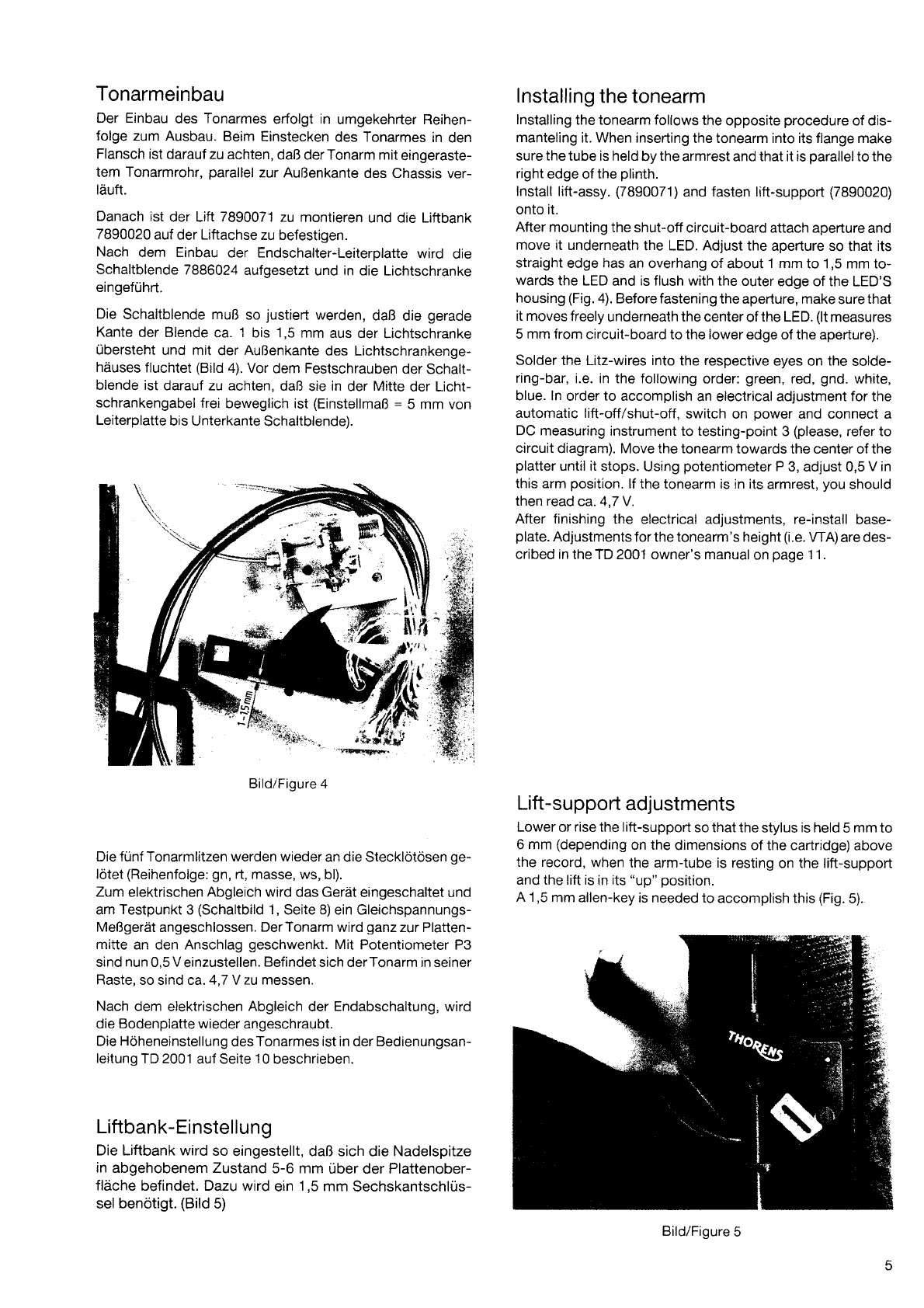
Die Schaltblende muB so justierl werden, daB die gerade
Kante der Blende ca. 1 bis 1,5 mm aus der Lichtschranke
rlbersteht und mit der AuBenkante des Lichtschrankenge-
hàuses Íluchtet (Bild 4). Vor dem Festschrauben der Schalt-
blende ist darauf zu achten, daB sie in der Mitte der Licht-
schrankengabel Írei beweglich ist (EinstellmaB : 5 mm von
Leiterplatte bis Unterkante Schaltblende).
Die frlnf Tonarmlitzen werden wieder an die Stecklötösen ge-
lötet (ReihenÍolge: gn, rt, masse, ws, bl).
Zum elektrischen Abgleich wird das Geràt eingeschaltet und
am Testpunkt 3 (Schaltbild 1, Seite 8) ein Gleichspannungs-
MeBgeràt angeschlossen. Der Tonarm wird ganz zur Platten-
mitte an den Anschlag geschwenkt. Mit Potentiometer P3
sind nun 0,5 V einzustellen. Befindet sich derTonarm in seiner
Raste, so sind ca. 4,7 Y zu messen.
Nach dem elektrischen Abgleich der Endabschaltung, wird
die Bodenplatte wieder angeschraubt.
Die Höheneinstellung des Tonarmes ist in der Bedienungsan-
leitung TD 2001 auf Seite 10 beschrieben.
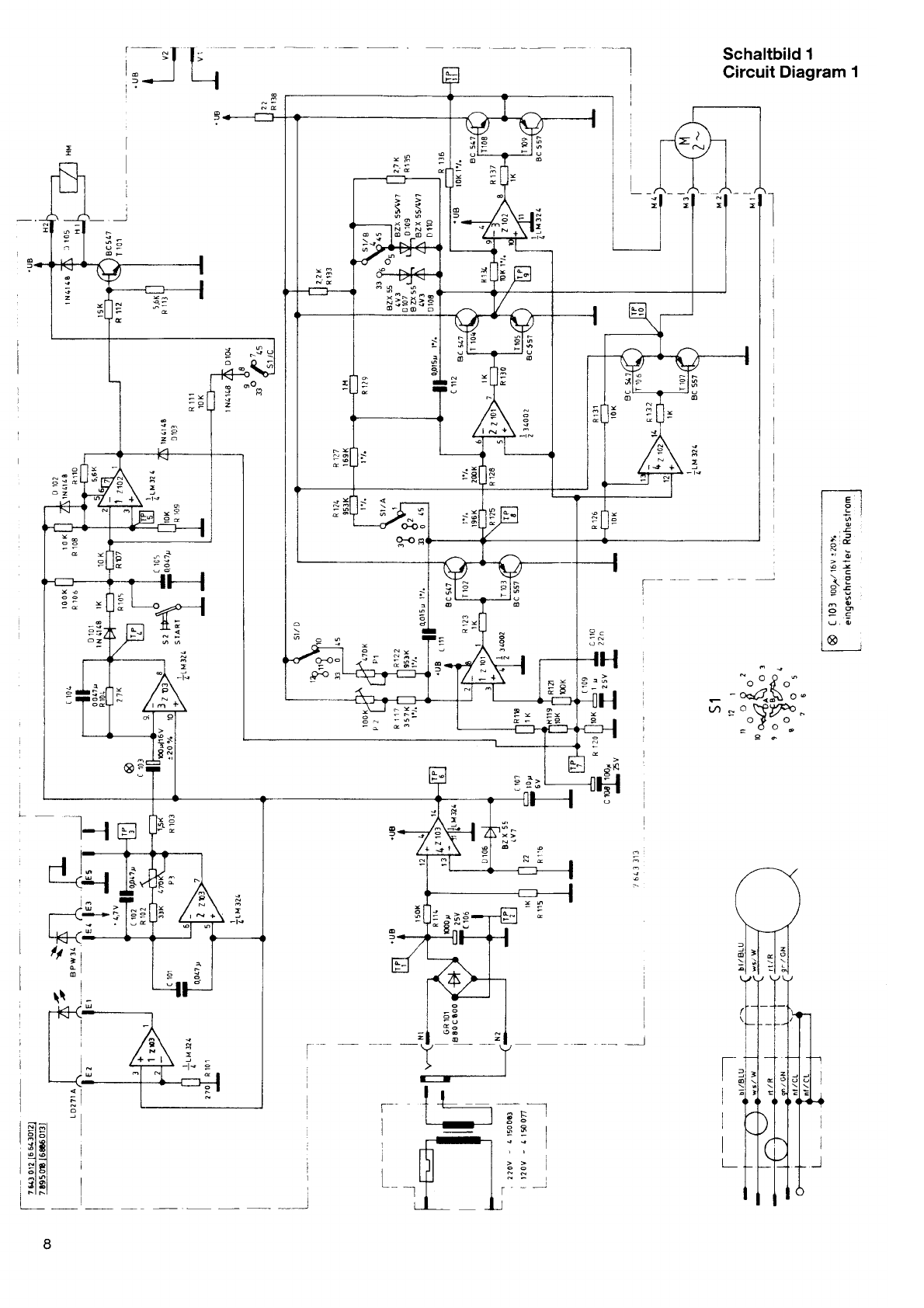
Liftbank-Einstellung
Die Liftbank wird so eingestellt, daB sich die Nadelspitze
in abgehobenem Zustand 5-6 mm uber der Plattenober-
flàche befindet. Dazu wird ein 1,5 mm Sechskantschlus-
selbenötigt. (Bild 5)
lnstalling the tonearm
lnstalling the tonearm follows the opposite procedure of dis-
manteling it. When inserting the tonearm into its flange make
sure the tube is held by the armrest and that it is parallel to the
right edge of the plinth.
lnstall lift-assy. (7890071) and fasten lift-support (7890020)
onto it.
After mounting the shut-off circuit-board attach aperture and
move it underneath the LED. Adjust the aperture so that its
straight edge has an overhang of about 1 mm to 1,5 mm to-
wards the LED and is flush with the outer edge of the LED'S
housing (Fig. a). Before fastening the aperture, make sure that
it moves freely underneath the center of the LED. (lt measures
5 mm from circuit-board to the lower edge of the aperture).
Solder the Litz-wires into the respective eyes on the solde-
ring-bar, i.e. in the following order: green, red, gnd. white,
blue. ln order to accomplish an electrical adjustment for the
automatic lift-off/shut-off, switch on power and connect a
DC measuring instrument to testing-point 3 (please, refer to
circuit diagram). Move the tonearm towards the center of the
platter until it stops. Using potentiometer P 3, adjust 0,5 V in
this arm position. lÍ the tonearm is in its armrest, you should
then read ca. 4,7 Y.
After finishing the electrical adjustments, re-install base-
plate. Adjustments Íor the tonearm's height (i.e. WA) are des-
cribed in the ïD 2001 owner's manual on page 1 1 .
Lift -support adjustments
Lower or rise the lift-support so that the stylus is held 5 mm to
6 mm (depending on the dimensions of the cartridge) above
the record, when the arm-tube is resting on the lift-supporl
and the lift is in its "up" position.
A 1,5 mm allen-key is needed to accomplish this (Fig. 5).
Bild/Figure 4
Bild/Figure 5
r

Antriebselektronik TD 2001
Der Plattenspieler ïD 200'1 wird mit einer Wechselstrom-
Niederspannung zwischen 16 und 19 Volt betrieben. Diese
Spannung lieÍert ein Steckertransformator. lhrAbsolutwert ist
von geringer Bedeutung, weil die Spannung nach der
Gleichrichtung fur die Versorgung kritischer Baugruppen
elektronisch stabilisierl wird.
Als Stabilisator wirkt einer der Operationsverstàrker aus dem
lC Z 103/4 in Verbindung mit der Zenerdiode D 106.
Vier Operationsverstàrker dienen in Verbindung mit ihren zu-
gehörigen Komplementàr-TransistorendstuÍen T 102 ... T 109
als Antriebselektronik fur den Synchronmotor M. DaÍ[rr sind
jeweils zwei dieser Verstàrker zu einer Bruckenschaltung zu-
sammengefaBt. Zwei Verstàrker speisen also je eine der bei-
den Motorwicklungen. Da diese Motorwicklungen um 90o
phasen verschoben angesteuert werden mr-issen, genugt
eine einÍache Ruckkopplung uber zwei frequenzbestim-
mende RC-Elemente, um die Schaltung gleichzeitig als Si-
nusgenerator Íur die Antriebsfrequenz wirken zu lassen.
Mit dem Potentiometer P 2 wird die Frequenzfijr33 1/3 U/min
und mit P 1 Íur 45 U/min eingestellt.
Endabschaltung
Der Verstàrker Z 1O3/3 wirkt durch die Beschaltung mit C 103
und R 104 als Differenzierer. Fàhrt die Abtastnadel in die Aus-
laufrille der Schallplatte, so wird die Ausgangsspannung von
2103/2 schnell erhöht. Die Spannung am Ausgang des Diffe-
renzierers Z 103/3 steigt inÍolgedessen auf einen Wert von
nahezu 15 V an. UOer D 101 , R 105 und R 107 wird der Ein-
gang der selbsthaltenden Triggerschaltung Z 102/1 ange-
steuefi, und am Ausgang fàllt die Spannung von.l 5 V auÍ
1,5 V zuruck. Der Transistor T 101 öffnet und schaltet den
Haltemagneten HM ab. Gleichzeitig wird uber D 103 die
Schwi ngung des Motor-Antriebsgenerators unterbrochen.
Soll der Antriebsmotor wieder gestartet werden, so wird der
Tastkontakt S 2 (STAR, geschlossen und der Eingang 2 des
Schwellwerlschalters Z 102/1 an 0 V gelegt. Der Ausgang von
Z 102/1 erhàlt eine Spannung 15 V. welche den Transistor T
101 durchschaltet.
Der Transistor T 101 versorgt den Haltemagneten HM. Durch
Absenken des Tonarms wird der Anker mechanisch angelegt
und elektrisch gehalten. Die DifÍerenzierschaltung Z 103/3
wird wirksam und damit auch die Endabschaltung. Der
gleichzeitig durch den R 121 u. C 110 ausgelöste Puls sorgt
fur ein schnelles Anschwingen des Generators.
Die Sperre uber D 103 wird aufgehoben, der Motor làuft an.
Drive Electronics TD 2001
TD 200'l turntables are powered Írom a low-voltage AC
source between 16 an 19 Volts. This voltage is provided by a
plug transformer. The exact value of the power voltage is oÍ
little importance, since it is rectified and electronically stabili-
zed for supplying critical components in the turntable.
Stabilization is perÍormed with the operational amplifier in
Z 103/4 together with Zener diode D 106.
Four operational amplifiers with the associated complemen-
tary power transistors T 102 - T 109 are arranged in two
bridge circuits as the drive electronics for the synchronous
motor M. Two ampliÍiers thus feed each of the two motor win-
dings. Since the winding drive signals must be separated by
an angle of 90', simple Íeedback through two frequency-de-
termining RC networks allows the circuit to be used simult-
aneously as a sinewave generator Íor the drive frequency.
The frequency for 33 1/3 rpm is adjusted with potentiometer
P 2,lor 45 rpm with P 1.
Auto-Stop
Amplifier Z 103/3 functions as a differentiator with C 103 and
R 104. When the pickup stylus enters the lead-out groove of
the record, the output voltage oÍ Z 103/2 quickly rises. The
voltage at the output of differentiator Z 1Q3/3 increases as a
result to a level near 15 V. The inpui of the latching trigger cir-
cuit is driven through D 101 , R 105 and R 107 and the voltage
at the output Íalls Írom 15 V to 1 .5 V. TransistorT 10'1 is turned
off, thus releasing holding magnet HM. Oscillation oÍ the mo-
tor drive generator is simultaneously interrupted via D 103.
The motor is restarted by closing pushbutton contact S 2
(STARï) and connecting input 2 oÍ threshold switch Z 102/1
to 0 V.A voltage oÍ 15 V appears at the output ol Z 102/1,tur-
ning on transistor T 101 .
TransistorT 101 switches holding magnet HM. Whilethetone
arm has been lowered, the armature is pulled in and held.
The difÍerentiating circuit Z 103/3 is activated and 1 03/3 the-
reby the auto-stop function, as well.
The interruption oÍ oscillation via D 103 is likewise cancelled,
and the drive motor starls.

Einstellungen und MeBwerte
Mit dem Potentiometer P 2 wird zuerst die Geschwindigkeit
33 1/3 U/min eingestellt, dann erÍolgt mit dem Potentiometer
P 1 die Einstellung fur 45 U/min. Diese ReihenÍolge ist unbe-
dingt einzuhalten!
Zur Geschwindigkeits-Ermittlung benutzt man zweckmàBi-
gerweise eine geeignete Stroboskopscheibe. Genauer wird
die Messung bei Verwendung einer MeBschallplatte in Ver-
bindung mit einem Zàhler.
Zur eventuell notwendigen Fehlerermittlung dienen die Span-
nungsangaben in Tabelle l.
Adjustments and Measurement Data
The speed is first adjusted for 33-1/3 rpm with potentiometer
P 2, and then for 45 rpm with potentiometer P 1. Do not
change this sequence.
A suitable stroboscope disk may be used for determining the
rotational speed. More exact measurements may be made
with a test record and electronic counter.
The voltage data in Table I may be used for determining pos-
sible defects.
Tabelle I Elektronik MeBwerte
Table I Circuit Measurements
Schalter^ -
Swltch §r U-
N,-N, t-
N.,-N, TP1 U-
TP5 U*
ïP6 U-
ÍP7 U-
TP 8-TP 11 ïP 8-ïP 11
Stop ca.19V 38 mA ca.24V 1,6V 4,7 V + $yo 1,4V 1,4V
33 U/min
laufend, running 17V 140 mA 19V 5,5 V
f.--
<f,
Ë
3e
CQ
:6G
d)o\:
>@ \u
5 +r.€
d,e HalÍie des MeBwer
tes ao TP l
Hatf oí lhe va ue
measuíed ai ÍP 1
+Ao/o / -60/o
3,3 Vdre Halfte des MeBwgr-
les an ÍP 1
HalíoÍ the value
measured at TP 1
+0o/o I -60/o
45 U/min
laufend, running '17 V 130 mA r9v 5,5 V4,0 v
33 U/min
stehend, stopped 19V 38 mA 24V 1,6V 1,4V 1,4V
45 U/min
stehend, stopped '19 v38 mA 24V 1,6V 1,4V 1,4V
Die Geschwindigkeitseinstellung 33 1/g U/min. bzw. 45 U/
min. kann auch bei geschlossenem Geràt vorgenommen
werden. Dafur ist in der Bodenplatte, im Einstellbereich der
Leiterplatte eine Bohrung angebracht (Bild 6).
Reihenfolge der Einstellung:
zuerst P 2,331/sUlmin.
dann P 1, 45 U/min.
Bezugspunkt fur alle Messungen ist TP
Reference point for all measurements is TP 2
Speed adjustments (33 1/s RPM and 45 RPM) can be execu-
ted even when the baseplate is in place.
A hole in the baseplate gives access to two potentiometers,
P 1 and P 2 (Fig. 6). Adjust P 2'for 33 1/s RPM first and then
P 1 for 45 RPM.
Bild/Figure 6
{Íàl
{":
;,'
o,o
P '1 t (5 U/mro
daid;Bi '
Schaltbild I
Circuit Diagram 1
9**
ot)
59
za
É
0
E
3rE
r5
{ts
=P
u, i
a
-
I
^ :^" -
o -rÍ o
- - o"./.§ o.
-':.Yfr"
9o
e.à
.l--r
l
I
I Èlil
r 3l5l
I :lel
-l nl
I rlsl
!
I
à
*3
@ó
f;
H
6:
OÈ
o -O-
z
:
Ë -r,
t--
l
,fl]
{
P
o
+
3==
.J3
@

!L_l Ël
5r '§Er rl
p
o gttu
G
-l-
,l 19
, L-l 61q
+-
=-ë'í=), ffi., -ffi
'=,*#':Ypï(ruï)F E
I
-
erPv.eolc gotu
Fil I D-lPtfiË*#- Ë
"ïl F {È lïEil}.".g-
z0tC zilo .-...G
,\--.i sl ' '=p*u
-l_#'=il*i^l :s
-J;r,;.,=Ci*ffi"r_# Ëf
E(f,r'. {+ *fr6'
tr=?ï?-ffi il*loq
*!;$Hsil #r
_r;'-EuJ -qg E Ë
l: -g_ __t<_ r ottc
I;:* * ll§+3
'=,nd- # L n
-.t-
9Z1U
-lr -
o
90r o
L Ë -,* fr \_i
C]
tLÉ

7 895 009
e lré!95!12
q-lx!l!g130
é
B- -:toos::ru
--ë95!?qj,!,r"-rry
7 895120 _c*1 lirqlel
_ó 89r 0_10_
._ 6gel00ó
.4x t- ?81 020
3x8aee0l §
- 4x*8 499-Ql1
I
)
,l.
%,,
3 x B r*99 001- V
" , ";; ;;;- É
\_-2}!!47!05
10
g* ?o! Q6;!-2oB
L 4x 8499011
&
7 895117
t7-8es017ÍlI
3x8499004 i

Ersatzteile
689501 1 Plexi HaubeTD2001
6 895 012 Gummiputfer
6 846 092 Gummiteller
6 895 500 PlattentellerTD 2001
7 895 009 AntriebstellerTD200l
6 800 574 Antriebsriemen
7 895 040 Mittellager kpl. TD 2001
8499 01 1 Schraube 3,5 x 20
9890020 TonarmTP90furïD2001
7 890 020 Liftbank kpl. TP 90
6890060 Fuhrungsbuchse
6890061 Mutter
8047005 GewindestiftM4x5
ab Serien-Nr. .....
6890062 Tonarm-Fuhrungsbuchse
8047011 GewindestiftM4xl6
8053210 Schraube M 5x 16
8508130 U-Scheibe5,3
7895020 GehàuseTD2001 Schwarz
7 895 120 GehàuseTD 200'l Mahag.
4281 013 Zierkappe Schwarz
7 895 017 NF-AnschluB-Blech kPl.
ab Serien-Nr. .....
7895117 NF-AnschluB-PanelkPl.
8 499 004 Schraube 3 x 1 7
4292O09 Federscharnier
6 895 005 ScharnierhalterTD 2001
8499 01 1 Schraube 3,5 x 20
7895007 Synchronmotorkpl.TD200l
8499004 Schraube3xlT
6 646 023 Fliemengabel
8499105 Schraube3xl3
7643 01 0 TasterkPl.
6520002 BedienknoPÍ
6 895 010 BedienblendeTD 2001
4281 O15 Deckel Schwarz
8699065 Rampa-MutterMl0
8053204 SchraubeM4x35
8 501 659 U-Scheibe 4,3
6 895 006 BodenplatteTD 2001
4287 O2O GummiÍuB Grau
8499 01 1 Schraube 3,5 x 20
8 062 208 Schraube 2,9 x 13
Replacement Parts
6 895 01 1 DustcoverTD200l
6 895 012 Buffer
6846092 Rubbermat
6 895 500 Turntable Platter TD 2001
7895 009 lnner platterTD2001
6 800 574 Drive belt
7 895 040 Bearing, comPlete TD 2001
8499 01 1 Screw 3,5 x 20
9890020 TonearmTP90forTD200l
7 890 020 Tonearm lift suPPott TP 90
6 890 060 Sleeve
6890061 Counter-nut
8047005 ScrewM4xS
from Serial No. .....
6890062 Tonearm-sleeve
8047011 ScrewM4xl6
8053210 ScrewM5x16
8508130 Washer5,3
7895020 PlinthTD2001 blackash
7895120 PlinthTD2001 mahoganY
4281 013 CovercaPblack
7 895 017 Signal-connection with
auto-sh ut-off ci rcuit-board
from Serial No. .....
7895117 Signal-connectionwith
auto-shut-otf circuit-board
8 499 004 Screw 3 x '17
4292009 Hinge
6 895 005 Hinge-mountTD 2001
8499 01 1 Screw 3,5 x 20
7 895 007 Synchronous motor, complete TD 2001
8499 004 Screw3x 17
6 646 023 Guiding fork
8499 105 Screw 3 x'13
7643 010 Switch-on, comPlete
6 520 002 Commutator knob
6 895 010 OPerating PanelTD 2001
4281 O15 CovercaP black
8699065 Counter-nut M 10
8053204 ScrewM4x35
8501659 Washer4,3
6 895 006 Base Plate TD 2001
4287O2O Rubberfoot
1499 01 1 Screw 3,5 x 20
B 062 208 Screw 2,9 x 13
{l
tt

7 64ó028
0-_
/:
L7:.--:
ea-lulaills
t789s0171
#
w
41 50 083
41 50078
4150077
41 50064
fu:*»u
-lÀó 89s 002
4240097
12
4x 8 499 105
ffi
Í:G
6'?\
6846093

Ersatzteile
7 643313 Steuerplatte kpl.
8499 105 Schraube3x 13
7643 006 Schalteinheit kpl.
7646028 Masseleitung-KontaktÍeder
4203325 Flachstecker
6646034 Bowdenzugkpl.
8499 105 Schraube3x 13
7890 071 Lift kpl.
Replacement Parts
7643 313 Circuit board, complete
8499105 Screw3x13
7643 006 Lift operating assembly, complete
7 646028 Ground cable
4203325 Plug
6 646 034 Bowden cable kpl.
8499105 Screw3x13
7 890 071 Lift complete
7895017 NF-AnschluB-Blechkpl. 78950'17 Signal-connectionwith
auto-shut-off circuit-board
ab Serien Nr...... from Serial No......
7895117 NF-AnschluB-Panelkpl. 7895 117 Signal-connection with
4312296 U-Scheibe .l 0,2 x 1 7 xo,75 auto-shut-off circuit-board
8 699 083 Mutter 10 x 0,75
7886024 Schaltblendekpl. 4312296 Washer10,2 x17 x0,75
8699 083 Counter-nut 10x0,75
6 646 005 Kontaktíeder 7 886024 Lift-off aperature, complete
4207 O81 Schelle
8499 105 Schraube3x 13 6646005 Ground contact-spring
4207 081 Cablefixing
T 646024 spannungs.-vers. Ltg. kpt. 8499 105 screw 3 x 13
6 643 025 AuÍnahmeblech 7 646O24 Voltage supply cable, complete
7646039 Einstellschraubekpl. 6643025 Powersocketsupport
7 89s 003 Auf hàngung 3 kpl. 7 646 039 sub-chassis adjustment screw
8499133 Schraube4,5x45
6 895 001 Seilsicherung 7 895 003 Spring holder 3, complete
6 895 002 Gummilager 8499 133 Screw 4,5 x 45
6 895 001 Cable check
4150083 SteckertraÍoEURO220V50Hz 6895002 Rubberbushing
oder
4150 078 Steckertrafo JAPAN 95 V 50l6OHz 4150 083 Plug-in transformer EURO 220 V 50 Hz
oder or
415O O77 SteckertraÍo CSA 120V 60 Hz 4150 078 Plug-in transÍormer JAPAN 95 V 5016OHz
oder or
41 50 064 SteckertraÍo UK 240 V 60 Hz 4150 077 Plug-in transÍormer CSA 120 V 60 Hz
or
6 846 093 Adapter 4150 064 Plug-in transformer UK 240V60 Hz
4240og7 Tonfrequenzteitung mit cINCH-Stecker 6 846 093 Adapter
4240O97 SignalinterconnectwithRCAplug
13
Table of contents
Other THORENS Turntable manuals

THORENS
THORENS TD 204 User manual

THORENS
THORENS TD 125 User manual

THORENS
THORENS TD 800 series User manual

THORENS
THORENS TD 1500 User manual

THORENS
THORENS TD 158 User manual

THORENS
THORENS TD 180 User manual

THORENS
THORENS TP 190 User manual

THORENS
THORENS TP 92 User manual

THORENS
THORENS TD 190-1 User manual

THORENS
THORENS TD 125 User manual

THORENS
THORENS TD 295 MK IV User manual

THORENS
THORENS TD 124 DD User manual

THORENS
THORENS TD 240-2 User manual

THORENS
THORENS TD 295 MK IV User manual

THORENS
THORENS TD 166 MKII User manual

THORENS
THORENS TD 309 User manual

THORENS
THORENS TD 165 User manual

THORENS
THORENS TD 2010 User manual

THORENS
THORENS TD 903 User manual

THORENS
THORENS TD 170-1 User manual


