© 2018 Thorlabs4
ERM100
1General Information
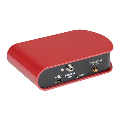
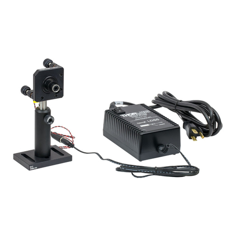
The ERM100 Benchtop Extinction Ratio Meter is designed to analyze the ER of laser light in a
polarization maintaining fiber for any kind of alignment applications like connectorization of PM
fibers or pigtailing of laser diodes with PM fibers.
The easy to use interface combined with a fast USB device interface open a wide range of ap-
plications in Manufacturing, Quality Control, Quality Assurance, and R&D.
Drivers for LabVIEW and C are available and makes it easy to integrate the instrument in test
and measurement systems
1.1 Safety
Attention
All statements regarding safety of operation and technical data in this instruction manual will
only apply when the unit is operated correctly as it was designed for.
The ER meter ERM100 must not be operated in explosion endangered environments!
Before applying power to your ERM100 system, make sure that the protective conductor of the
3 conductor mains power cord is correctly connected to the protective earth contact of the
socket outlet!
Improper grounding can cause electric shock with damages to your health or even death!
All modules must only be operated with proper shielded connection cables.
Only with written consent from Thorlabs may changes to single components be carried out or
components not supplied by Thorlabs be used.
Do not obstruct the air ventilation slots in housing!
Do not remove covers!
Refer servicing to qualified personal!
This precision device is only serviceable if properly packed into the complete original packaging
including the plastic foam sleeves. If necessary, ask for a replacement package.
Attention
Mobile telephones, cellular phones or other radio transmitters are not to be used within the
range of three meters of this unit since the electromagnetic field intensity may then exceed the
maximum allowed disturbance values according to IEC 61326-1.
This product has been tested and found to comply with the limits according to IEC 61326-1 for
using connection cables shorter than 3 meters (9.8 feet).
Vous pouvez trouver les traductions françaises des paragraphes ayant trait à la sécurité
d'utilisation de ce produit sur le lien suivant:
http://www.thorlabs.com/thorcat/17500/ERM100-CSADocument(Français).pdf
Vous pouvez aussi simplement scanner le code QR
