HBK PAD4001A User manual

PAD4001A, PAD4003A
ENGLISH DEUTSCH FRANÇAIS
Operating Manual
Bedienungsanleitung
Manuel d'emploi

Hottinger Brüel & Kjaer GmbH
Im Tiefen See 45
D-64293 Darmstadt
Tel. +49 6151 803-0
Fax +49 6151 803-9100
www.hbkworld.com
Mat.: 7-1001.4238
DVS: A04238 01 Y00 01
11.2021
EHottinger Brüel & Kjaer GmbH
Subject to modifications.
All product descriptions are for general information
only. They are not to be understood as a guarantee of
quality or durability.
Änderungen vorbehalten.
Alle Angaben beschreiben unsere Produkte in allge
meiner Form. Sie stellen keine Beschaffenheits- oder
Haltbarkeitsgarantie dar.
Sous réserve de modifications.
Les caractéristiques indiquées ne décrivent nos
produits que sous une forme générale. Elles
n'impliquent aucune garantie de qualité ou de
durabilité.
PAD4001A, PAD4003A
ENGLISH DEUTSCH FRANÇAIS
Operating Manual

PAD4001A, PAD4003A
TABLE OF CONTENTS
2
TABLE OF CONTENTS
1 Safety instructions 3................................................
2 Markings used 6....................................................
2.1 Symbols on the device 6.............................................
2.2 The markings used in this document 6.................................
3 Structure and mode of operation 7....................................
3.1 Structure of the electronics 7.........................................
3.2 Signal conditioning 8................................................
3.3 Adaptive interference suppression 9...................................
3.4 Inputs and outputs 9................................................
3.4.1 Trigger function 10...................................................
3.4.2 Filling and dosing 10.................................................
3.4.3 Limit value function 10................................................
3.4.4 Extreme value functions 10............................................
4 Conditions on site 11.................................................
5 Mechanical installation 12............................................
5.1 Important precautions during installation 12..............................
5.2 Dimensions 12......................................................
6 Electrical connection 13..............................................
6.1 Cable laying 13......................................................
6.2 Pin assignment 13...................................................
6.3 Supply voltage 15....................................................
7 Interfaces 17........................................................
7.1 RS‐485 4‐wire interfaces (UART) 17.....................................
7.2 CANopen interface 18................................................
8 Operation via software 20.............................................
9 Environmental protection 20..........................................

3
PAD4001A, PAD4003A
SAFETY INSTRUCTIONS
1 SAFETY INSTRUCTIONS
Appropriate use
PAD digital transducer electronics are to be used exclusively for measurement tasks and
directly related control tasks within the application limits detailed in the specifications.
Any other use is not appropriate.
Any person instructed to carry out installation, commissioning or operation of the device
must have read and understood the Operating Manual and in particular the technical
safety instructions.
In the interests of safety, the device should only be operated by qualified personnel and
as described in the Operating Manual. It is also essential to comply with the legal and
safety requirements for the application concerned during use. The same applies to the
use of accessories.
PAD is not intended for use as a safety component. Please also refer to the "Additional
safety precautions" section. Proper and safe operation requires proper transportation,
correct storage, siting and mounting, and careful operation.
Operating conditions
SPlease observe the allowed maximum values stated in the specifications for:
-Max. supply voltage
-Max. voltage for inputs and outputs
-Max current of outputs
-Temperature limits
SMake sure that the max. current for plugs and sockets is adhered to in bus mode.
SThe device must not be modified from the design or safety engineering point of view
except with our express agreement. In particular, any repair or soldering work on
motherboards (exchanging components) is prohibited.
SThe device is delivered from the factory with a fixed hardware and software configura
tion. Changes can only be made within the possibilities listed in the corresponding
documentation.
SThe device is maintenance free.
SPlease note the following points when cleaning the housing:
-Disconnect the device from all current and voltage supplies before cleaning it.
-Clean the housing with a soft, slightly damp cloth. Never use solvent, as this could
damage the label or the housing.
-When cleaning, ensure that no liquid gets into the device or connections.
SIn accordance with national and local environmental protection and material recovery
and recycling regulations, old equipment that can no longer be used must be disposed
of separately and not with normal household garbage, see Chapter9 on page20.

PAD4001A, PAD4003A
SAFETY INSTRUCTIONS
4
Qualified personnel
Qualified persons means persons entrusted with the installation, fitting, commissioning
and operation of the product who possess the appropriate qualifications for their func
tion.
This includes people who meet at least one of the three following requirements:
SKnowledge of the safety concepts of measurement and automation technology is a
requirement and as project personnel, they must be familiar with these concepts.
SAs measurement or automation plant operating personnel, they been instructed how
to handle the machinery. They are familiar with the operation of the equipment and
technologies described in this documentation.
SAs commissioning engineers or service engineers, they have successfully completed
the training to qualify them to repair the automation systems. They are also author
ized to activate, ground and label circuits and equipment in accordance with safety
engineering standards.
Working safely
SThe device must not be directly connected to the power supply system. The supply
voltage must be between 12 and 30VDC.
SError messages should only be acknowledged once the cause of the error is removed
and no further danger exists.
SAutomation equipment and devices must be designed in such a way that adequate
protection or locking against unintentional actuation is provided (e.g. access checks,
password protection, etc.).
SFor those devices operating in networks, safety precautions must be taken both in
terms of hardware and software, so that a line break or other interruptions to signal
transmission do not cause undefined states or loss of data in the automation device.
SAfter making settings and carrying out activities that are password-protected, ensure
that any controls that may be connected remain in a safe condition until the switching
performance of the device has been tested.
Additional safety precautions
Additional safety precautions to meet the requirements of the relevant national and local
accident prevention regulations must be taken in plants where malfunctions could cause
major damage, loss of data or even personal injury.
The scope of supply and performance of the device covers only a small area of measure
ment technology. Before starting up the device in a system, a project planning and risk
analysis must first be implemented, taking into account all the safety aspects of meas
urement and automation technology so that residual risks are minimized. This particu
larly concerns personal and machine protection. In the event of a fault, the relevant pre
cautions must establish safe operating conditions.

5
PAD4001A, PAD4003A
SAFETY INSTRUCTIONS
General dangers of failing to follow the safety instructions
The device is state of the art and failsafe. The device may give rise to residual dangers if
it is inappropriately installed or operated.
PAD4001A, PAD4003A
MARKINGS USED
6
2 MARKINGS USED
2.1 Symbols on the device
CE mark
The CE mark enables the manufacturer to guarantee that the
product complies with the requirements of the relevant EC dir
ectives (the Declaration of Conformity can be found on the HBM
website (www.hbm.com) under HBMdoc).
Statutory waste disposal mark
In accordance with national and local environmental protection
and material recovery and recycling regulations, old devices that
can no longer be used must be disposed of separately and not
with normal household garbage. Also see Chapter9 on page20.
2.2 The markings used in this document
Important instructions for your safety are specifically identified. It is essential to follow
these instructions in order to prevent accidents and damage to property.
Symbol Significance
NOTICE This marking draws your attention to a situation in
which failure to comply with safety requirements can
lead to damage to property.
Important
This marking draws your attention to important in
formation about the product or about handling the
product.
Tip
This marking indicates application tips or other
information that is useful to you.
Information
This marking draws your attention to information
about the product or about handling the product.
Emphasis
See …
Italics are used to emphasize and highlight text and
identify references to sections, diagrams, or external
documents and files.
uThis marking indicates an action in a procedure
7
PAD4001A, PAD4003A
STRUCTURE AND MODE OF OPERATION
3 STRUCTURE AND MODE OF OPERATION
PAD digital transducer electronics are part of the family of electronics developed by HBM
for static and dynamic weighing processes. They record the measurement signals of
connected sensors with strain gages. The transducer electronics digitally condition the
signals and deliver a fully-filtered, scaled and digitized output signal for direct connection
to bus systems or PCs via the RS‐485 interface or CANopen. The electronics can be
quickly and easily matched to a particular system by various parameters, and they work
with an internal data rate of up to 1200 measurements per second.
The inbuilt digital inputs and outputs allow event-driven weight determination, e.g. for
checkweigher applications or dosing controls. The digital outputs can be configured by
software command, and can be used to control coarse flow and fine flow in dosing
valves, for example.
The PanelX software is available as a free download from the HBM website for setting all
the parameters in full, for realizing dynamic measurement signals, and for frequency ana
lysis of the dynamic system: http://www.hbm.com/software
.
Information
This part of the operating manual describes the hardware and the functions of the elec
tronics. The communication commands and detailed configuration instructions for various
applications are included in the online documentation of the PanelX program.
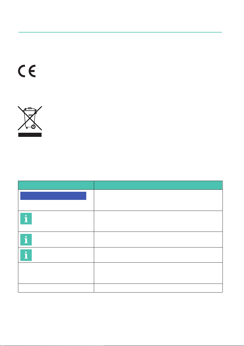
3.1 Structure of the electronics
Voltage
control
Interface
I/Os
Supply voltage
UB/GND
Interface
RS-485/CANopen
IO
Trigger,
Stop Dosing
EEPROM
Linearization
Serial number
Digital filter
Data rate
Sensitivity
Zero value
μP
A
D
PAD
Fig. 3.1 Block diagram

PAD4001A, PAD4003A
STRUCTURE AND MODE OF OPERATION
8
The analog transducer signal is first amplified, then analog filtered, and digitized in the
A/D converter. This signal is processed in the microprocessor and can be transmitted
over the interface. Digital inputs/outputs are available for control. The electronics have
various programs for applications such as filling, dosing, checkweighers or weight grad
ing machines. All the parameters can be stored power failsafe.
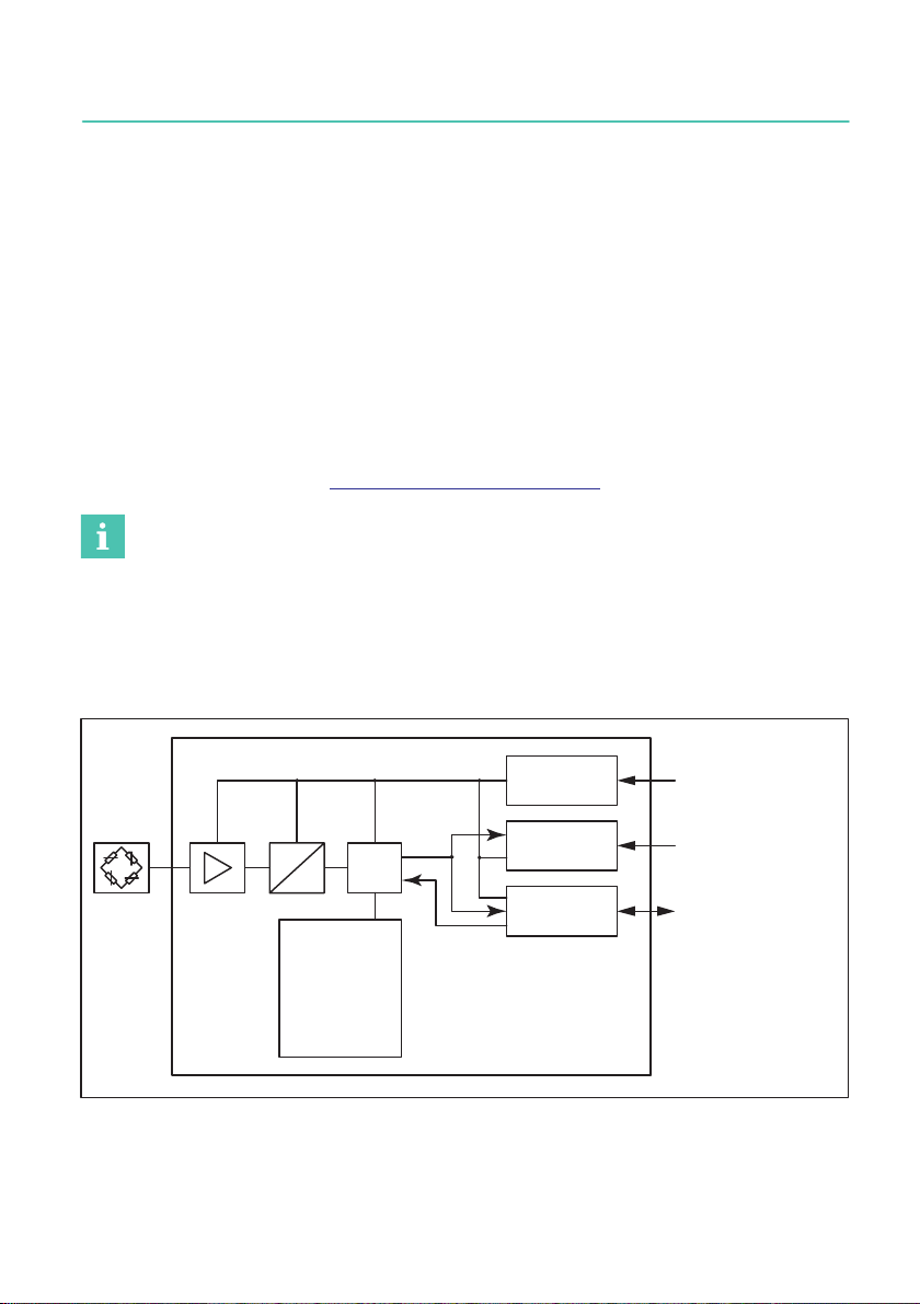
3.2 Signal conditioning
FMD
ASF ICR
SZA
SFA
NOV, RSN
LDW, LWT LIC
PVA
IMD
LIV
TAV, TAS Net
meas.
value
Gross
meas
.value
Extreme
values
Trigger/
Stop
Limit
values
Sam
pling
rate
Working
standard
calibration
Filter Tare
A
D
User‐defined
scaling
Lin
earization
Min/
Max
Trigger
Limit
values
RUN
BRK
Coarse Flow
Fine Flow
Ready
Alarm
Dosing control
Fig. 3.2 Signal conditioning
Digitization is followed by filtering, using digital filters adjusted by the software. The com
mand ICR changes the output rate (measured values per second).
In the working standard calibration of the electronics (on delivery), 0 mV/V corresponds
to zero and the maximum capacity is either 1,000,000digits (NOV≠0), or 5,120,000digits
(NOV=0). The two parameters LDW and LWT give you the opportunity to adapt the char
acteristic curve to meet your requirements (scale curve) and you can use the NOV com
mand to standardize the measured values to the required scaling value (e.g. 3000d).
Detailed information can be found in the command documentation and in the Online Help
for the PanelX program.
You also have the opportunity to
Sswitch from gross to net signals,
Sactivate an automatic zero on start up function,
Sactivate an automatic zero tracking function,
Slinearize the input signal with a third order polynomial,

9
PAD4001A, PAD4003A
STRUCTURE AND MODE OF OPERATION
Sactivate various digital filters. Available filters include those with cut-off frequencies
below 1Hz, fast-settling filters for dynamic measurements, notch filters and mean
value filters.
Use MSV? to read out the current measured value. The format of the measured value
(ASCII or binary) is set with the COF command. You can also use the COF command to
activate automatic measurement output. The measured values are transmitted in the
following format, subject to the COF command:
Output format Input signal Output when NOV=0 Output when
NOV>0
Binary, 2 chars. (INT) 0 …maximum
capacity
0 …20,000digits 0 …NOV
Binary, 4 chars. (LONG) 0 …maximum
capacity
0 …5,120,000digits 0 …NOV
ASCII 0 …maximum
capacity
0 …1,000,000digits 0 …NOV
3.3 Adaptive interference suppression
Whatever the mode of operation, you can use the ADF command to activate automatic
interference suppression with adaptive filters. Interference frequencies are automatically
found during measurement and suppressed by comb filters and averaging. The max
imum filter settling time can be limited with the TMA command.
3.4 Inputs and outputs
The two I/Os can be used either as inputs or outputs. You can also set different switching
levels (TTL or PLC) for the inputs. On delivery, both I/Os are set as inputs with a TTL level.
Specify the function of the I/Os as inputs with commands IM1 and IM2, and the function
as outputs with OM1 and OM2.
Notice
The electronics must be operated with a supply voltage of between 12 and 30V. Incorrect
connections between the supply and interface cables or digital inputs/outputs can cause
irreversible damage.
Check the correct assignment of the connections before switching on for the first time.

PAD4001A, PAD4003A
STRUCTURE AND MODE OF OPERATION
10
3.4.1 Trigger function
In Trigger mode (command IMD1), the electronics have four different trigger functions:
SPre-triggering by level
SPre-triggering by external (digital) signal
SPost-triggering by level
SPost-triggering by external (digital) signal
Gross or net values can be used as input values. The filter settling time can be optimized
by the actual electronics (command AST).
3.4.2 Filling and dosing
The electronics include full dosing control (command IMD2). As many as 32 parameter
sets can be stored in the EEPROM for different applications. But you can still change the
dosing parameters yourself during dosing. Digital outputs can be used to control coarse
and fine flow, for example. The PanelX software includes detailed instructions for setting
the different parameters.
3.4.3 Limit value function
In Standard and Trigger modes (command IMD), the electronics allow as many as four
limit values to be monitored (command LIV). Gross or net values, the trigger result, or the
extreme values (Min/Max) are available to you as input signals. Use the measurement
status to read out the status, either simultaneously with the measured values (command
MSV?) or separately (command RIO?).
3.4.4 Extreme value functions
The electronics include a peak value function (Minimum and Maximum, command PVS),
that monitors either the gross or net values, as required. Use command PVA to read out
the values and use command CPV to reset the peak values.

11
PAD4001A, PAD4003A
CONDITIONS ON SITE
4 CONDITIONS ON SITE
The PAD is hermetically encapsulated by laser welding and is made from materials that
do not rust. They are therefore largely impervious to humidity and moisture. The devices
achieve protection classes IP68 (test conditions: 100 hours under 1m water column) and
IP69K (water at high pressure, steam cleaning), as per DIN EN605291). The devices
should nevertheless be protected against the long-term effects of moisture and humidity.
Important
Note that when using a steam cleaner, the conditions stated in EN 60529 under degree of
protection IP69K such as max. pressure, max. temperature, etc., must be met.
Protection against corrosion
The device must be protected against chemicals that could attack the steel of the hous
ing, the plugs or the cables.
Information
Acids and all substances that release ions also attack stainless steels and their seam
welds.
Subsequent corrosion can cause the device to fail. If this is the case, you must provide
appropriate means of protection.
1) With fitted plugs of the same protection class.
PAD4001A, PAD4003A
MECHANICAL INSTALLATION
12
5 MECHANICAL INSTALLATION
5.1 Important precautions during installation
Welding currents must not be allowed to flow over the electronics. If there is a risk that
this might happen, you must provide a suitable low-ohm connection to electrically bypass
the electronics.
Notice
PAD electronics are precision measuring elements, and need to be handled carefully. Drop
ping or knocking them may cause permanent damage. Tighten the plug during installation
with a torque of max. 4Nm.
Important
Before mounting several weighing modules into an installation with a bus system, take the
following into account:
The printed production number (type plate) is required for setting up data communication.
If the type plate can no longer be seen after installation, the numbers of each weighing
module should be noted beforehand. This enables different addresses to be assigned dur
ing the initial start-up.
Alternatively, before connection to the bus system, you can connect each weighing module
individually with a PC, in order to set different addresses (see ADR command in the Online
Help).
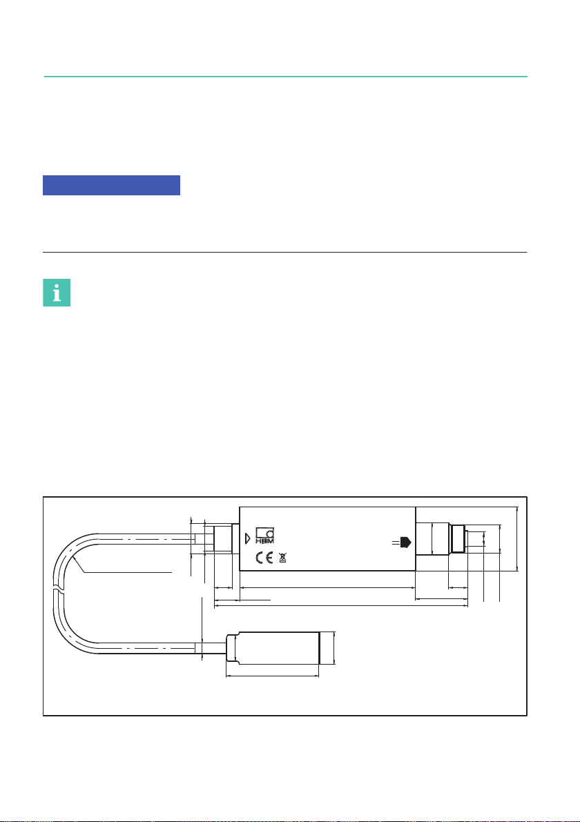
5.2 Dimensions
smallest bending
radius
26 (mobile 52)
126.7+1 26
9.5
16
M14x1
∅32
∅15
∅12.4
12.7+1
13 AF
46
∅161)
∅142)
∅5.3±0.2
9+1 88
M12x1
Serial No.: nnnnnnn
Year: yyyy
Type : PAD4001A-xxx
UB=+12V...+30V
IB, max = 1.1A
1) 4001A: PW15PH, PW25P, PW28PH, PW29P
2) 4003A: PW27AP
Fig. 5.1 Dimensions

13
PAD4001A, PAD4003A
ELECTRICAL CONNECTION
6 ELECTRICAL CONNECTION
Notice
Electronic components are sensitive to electrostatic discharge (ESD). So you must dis
charge your own static electricity before touching the connector plugs.
6.1 Cable laying
Position the connection cable so that any condensation or moisture that may occur at the
cable can drip off (loop). It must not be able to reach the electronics. Also make sure that
it is not possible for humidity or moisture to get into the cables through open ends, thus
preventing damage to the cable sheath.
6.2 Pin assignment
Notice
The electronics must be operated with a supply voltage of between 12 and 30V. Incorrect
connections between the supply and interface cables or the digital inputs/outputs can
cause irreversible damage.
So you must check the correct assignment of the connections before switching on for the
first time.
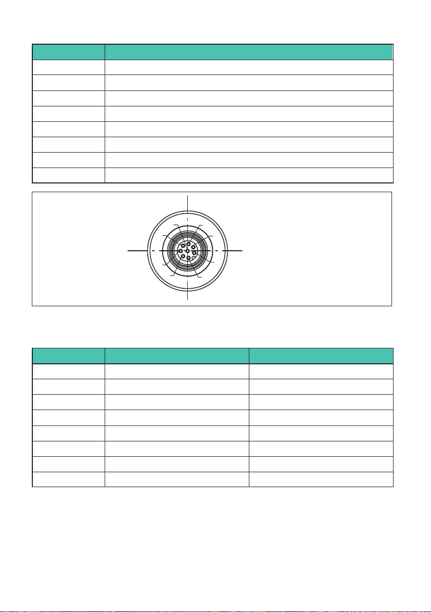
The electronics have an 8‐pin connector plug (M12) for connecting to a transducer
(Fig. 6.1).
1
2
345
6
7
8
Fig. 6.1 M12 connector plug, 8-pin, for transducers
PAD4001A, PAD4003A
ELECTRICAL CONNECTION
14
Pin Transducer connection
1Measurement signal (+)
2Not in use
3Additional excitation voltage line (+)
4Not in use
5Additional excitation voltage line (-)
6Bridge excitation voltage (-)
7Bridge excitation voltage (+)
8Measurement signal (-)
6
8
5
4
32
1
7
Fig. 6.2 Connector socket with M12 internal thread (for 1-KAB165) and M14 external
thread (for 1-KAB173), 8-pin, digital output
Pin RS-485 CANopen
1 GND GND
2I/O 2 I/O 2
3 RA CAN High IN
4I/O 1 I/O 1
5 RB CAN Low IN
6 TB CAN Low OUT
7 TA CAN High OUT
812 …30V 12 …30V
Suitable connection cables and the color code used can be found in the HBM data sheet
"Cables with a plug", B3643.

15
PAD4001A, PAD4003A
ELECTRICAL CONNECTION
Please note:
SWith the CAN interface, you must use a cable with a characteristic impedance of ap
prox. 120Ω. HBM cable 1-KAB173 meets these requirements and also has the same
protection class (IP68/69K) as the PAD housing.
SThe housing of the PAD is connected to the cable shield by the connector socket. To
obtain an EMC-compliant connection (EMC = electromagnetic compatibility), the
shield of this cable must be connected to the housing of the connected electronics or
to ground potential. A direct, low-ohm contact must be made with the shield, by EMC-
compliant plug connections, for example.
SShould it be necessary, a separate cable can be used to establish potential equaliza
tion between the electronics and the (PC/PLC) master (grounding concept). You must
not use the cable shield for this potential equalization.
SUse shielded, low-capacitance cables only for all connections (interface, power supply
and additional devices) - (HBM cables meet these requirements).
SElectrical and magnetic fields often induce interference voltages in the measurement
electronics. Do not route the measurement cables parallel to power lines and control
circuits. If this is not possible, protect the measurement cable (e.g. with a rigid steel
conduit, minimum size M25). A minimum distance of 20mm must be maintained
between the cables to the analog transducers and other transducer cables installed in
parallel.
6.3 Supply voltage
Regulated dc voltage of +12 to +30 V is required to operate the electronics and serial
communication.
Voltage source requirements
SThe supply voltage must be sufficiently smoothed (RMS value minus residual ripple >
12 V).
SThe electronics have a low-loss controller with a power consumption of 3 W during
operation. The current consumption is therefore dependent on the level of the supply
voltage:
3
Voltage in V
W
Power requirement in A =
SWhen switched on, the electronics briefly consume a current of approx. 0.15 A. To
ensure a safe start-up, the power supply must be able to provide this current without a
limit being triggered. This is particularly important when supplying several PADs from
one power supply. In contrast, the sustained loading is calculated from the formula
shown above.
SConnection to a wide-ranging supply network is not permitted as this often causes
interfering voltage peaks to be induced. Instead, a local supply must be provided for
the electronics (even when grouped).

PAD4001A, PAD4003A
ELECTRICAL CONNECTION
16
SThe supply voltage must be insulated from the shield potential. A connection from
GND to the housing is not required, but the max. potential difference must be no more
than 7 V.
SThe supply voltage ground wire (GND) is also used as the reference potential for the
interface signals and the digital inputs/outputs.
SIn layouts with several PADs, the supply can run together with the RS-485 bus lines in
a 6-pin cable (with HBM junction boxes, for example). Ensure that there is sufficient
wire cross-section provided, as some cable sections will conduct the supply current
for all the connected PADs.

17
PAD4001A, PAD4003A
INTERFACES
7 INTERFACES
The electronics interface is referenced to GND. The master interface must also be refer
enced to GND.
Use a shielded cable as the interface cable. The shield should always be connected to the
housing at both ends. The shield of the electronics cable must be electrically connected
to the housing of the electronics.
Important
Before mounting several PADs into an installation with a bus system, take the following
into account:
The printed production number (type plate) is required for setting up data communication.
If the type plate can no longer be seen after installation, the numbers of each PAD should
be noted beforehand. This enables different addresses to be assigned during the initial
start-up.
Alternatively, before connection to the bus system, you can connect each PAD individually
with a PC, in order to set different addresses (see ADR command in the Online Help).
7.1 RS‐485 4‐wire interfaces (UART)
The electronics come supplied with an RS-485 interface. Bit rates of 1200 to 115,200
baud can be set for the interface. The ground reference for all the interface signals is
based on the supply voltage ground (GND).
Either a single PAD can be connected via the RS485 interface, or you can set up a bus
system to connect as many as 90 PADs to an RS485 interface. All the PADs are connec
ted in parallel on a line, the total length of the line can be as much as 500m. The software
uses the different addresses to differentiate between the PADs. If the control computer
only has an RS-232 interface, an interface converter is required (e.g. from HBM, ordering
no.: 1-SC232/422B).
PAD4001A, PAD4003A
INTERFACES
18
Bus termination Bus termination
TB
TA
RB
RA
PC = Master Node 1 Node 90
...
500 Ω
500 Ω
500 Ω
500 Ω
500 Ω
500 Ω
500 Ω
500 Ω
+5 V
+5 V
+5 V
+5 V
TxD on/off RxD
TB TA
TR
RB RA
TxD on/off RxD
TB TA
TR
RB RA
TxD on/off RxD
TB TA
TR
RB RA
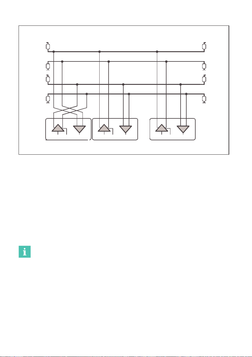
Fig. 7.1 Connecting several PADs to a PC via an RS‐485 4‐wire bus
The correct assignment of the transmit and receive lines can be seen in Fig. 7.1 (bus line
Ra to Ta of the converter, etc.). The electronics already include bus termination resistors
(line termination), that can be activated with the software command STR. So no addi
tional bus termination resistors are required for RS-485.
7.2 CANopen interface
The interface design follows the CiA DS301 CANopen standard. The address on delivery
is 63.
The CAN bus is set up as a 2‐wire line (CANH and CANL) (see ISO11898).
Important
You must connect bus termination resistors (each 120W) at the start and at the end of the
bus. The electronics do not contain a bus termination resistor for CANopen.
This manual suits for next models
1
Table of contents
Languages:
Other HBK Measuring Instrument manuals


Popular Measuring Instrument manuals by other brands


PPS
PPS PPS71 user manual

PCB Piezotronics
PCB Piezotronics IMI SENSORS 601A62 Installation and operating manual

ADA INSTRUMENTS
ADA INSTRUMENTS WHEEL 50 DIGITAL operating manual

Stanford Research Systems
Stanford Research Systems SR785 Operating manual and programming reference

Bartec
Bartec Tech200 user guide

YOKOGAWA
YOKOGAWA ST401G user manual


