Valeport 801 EM User manual

Document Ref:
Date:
This document was prepared by the staff of Valeport Limited, the Company, and is the property of
the Company, which also owns the copyright therein. All rights conferred by the law of the
copyright and by virtue of international copyright conventions are reserved to the Company. This
document must not be copied, reprinted or reproduced in any material form, either wholly or in
part, and the contents of this document, and any method or technique available therefrom, must
not be disclosed to any other person whatsoever without the prior written consent of the
Company.
Valeport Limited
St Peters Quay
Totnes
Devon, TQ9 5EW
United Kingdom
As part of our policy of continuous development, we reserve the right to alter, without prior
notice, all specifications, designs, prices and conditions of supply for all our equipment.
0801852a
08 August 2016
+44 1803 869292
sales@valeport.co.uk
www.valeport.co.uk
Tel:
e mail:
Web:
Model 801 EM
Current Meter
Operating Manual

Table of Contents
Page 2Page 2
Table of Contents
..................................................................................................................................... 31. Introduction
..................................................................................................................................... 42. Equipment
.................................................................................................................................... 42.1. Standard 801 System
.................................................................................................................................... 42.2. Wading Accessories
.................................................................................................................................... 42.3. Options
..................................................................................................................................... 53. Description
..................................................................................................................................... 84. System Operation
.................................................................................................................................... 84.1. Setting Up
.................................................................................................................................... 84.2. Switch On
.................................................................................................................................... 94.3. Running the Unit
.................................................................................................................................... 104.4. Setting Units, Averaging Mode and Averaging Period
.................................................................................................................................... 114.5. Option Menu
.................................................................................................................................... 124.6. Logging Menu
.................................................................................................................................... 154.7. Sub Options Menu
.................................................................................................................................... 164.8. Analogue Output [Factory Fit Option]
..................................................................................................................................... 175. Power Supply
.................................................................................................................................... 175.1. Changing Batteries
.................................................................................................................................... 175.2. Battery Life
.................................................................................................................................... 185.3. External Power [Factory Fit Option]
..................................................................................................................................... 196. Calibration
.................................................................................................................................... 216.1. Adjusting Zero Offset
..................................................................................................................................... 237. Care and Maintenance

Introduction Page 3
© 2016 Valeport Ltd
1. Introduction
This manual covers the operation of the Valeport Model 801 Electromagnetic Flow Meter.
Flat Type - 0801001
Cylindrical Type - 0801002

Model 801 EM Current Meter
Page 4
© 2016 Valeport Ltd
2. Equipment
2.1. Standard 801 System
The standard 801 system has a choice of sensors and comprises the following. Both can be used
with either 19 or 20mm diameter wading rods which customers may already have for use with
impeller current meters:
0801013
Single axis, cylindrical sensor c/w 2m cable and connector
or
0801004
Single axis, flat sensor c/w 2m cable and connector
0801006
Wading Rod adaptor [only supplied for the flat sensor 0801004]
0801007
Allen Key for wading rod adaptor
0801005
Control and Display Unit
0801008
Carrying case
0801811
Operating manual
2.2. Wading Accessories
The following accessories are available for wading operations:
0801003
Set of 3 off 0.5 metre wading rods, graduated in centimetres, base and direction
knob
0801010
Canvas shoulder bag for wading accessories
2.3. Options
0300012
Data cable to computer
0801011
Larger carrying case to take complete system with wading rods [instead of
standard case and canvas shoulder bag]
0801017
Analogue output option

Description Page 5
© 2016 Valeport Ltd
3. Description
The 801 electromagnetic flow meter uses the Faraday principle to measure the flow of water past
the sensor. Two different types of sensor are available for the 801: the cylindrical sensor and flat
sensor.
The cylindrical sensor has its electrodes on the side and the volume of water that is being sensed is
a spherical volume around the sensor to a diameter of about 120mm. Because of this relatively
large sensing volume, the cylindrical sensor should not be used in situations where the water
boundary [bottom, sides or surface] is closer than 40mm to the sensor.
The flat sensor has the sensing electrodes on one surface of the sensor and these should normally
be facing uppermost. The volume of water whose flow is being sensed is a cylinder between the
electrodes and extending to approximately 10mm above the sensor. This sensor is therefore also
suited to shallow applications. Because of the small sensing volume, if the water is turbulent, the
real time readings of the flat sensor will fluctuate more than those of the cylindrical sensor.
The sensor should be aligned into the flow and the calibration is determined for +ve flow [flow on
to the sensor at the electrode end] with the sensor upstream of the wading rod.
The sensor will detect negative flow and the same calibration is used, although there will normally
be some interference caused by the turbulence from the wading rods. The unit is set to measure
speeds up to 5 M/sec in both directions.

Model 801 EM Current Meter
Page 6
© 2016 Valeport Ltd
The system is calibrated as a combination of sensor with electronics in the Control Display Unit, and
the serial number of both the probe and the CDU are displayed on the display on start up.
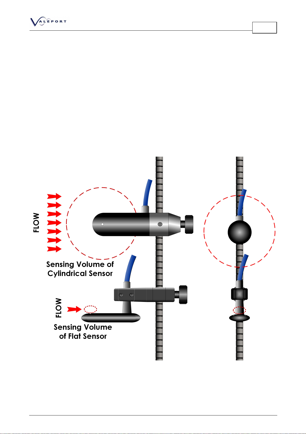
The system will operate in any conducting fluid, and the conductivity does not effect calibration.
At very low conductivities the signal will, however, become noisier. A simple check is to check the
noise in still water.
The CDU has its own internal batteries, and bulkhead connectors for the data interface to PC and
the sensor. There is also a waterproof pressure equalising valve, to compensate for changes in
temperature and atmospheric pressure that would otherwise cause the display membrane to
distort. The connectors have waterproof pro-caps for when not in use. The CDU is designed for
operation in rain conditions and for temporary immersion in water to 0.3m for 10 seconds,
provided all connectors or pro-caps are fitted.
The EM system measures the flow twice every second, and calculates the real time flow every
second as the average of the half second readings. The REAL TIME display is updated every second.
The average speeds are computed as the average of the one second real time values over the
averaging period which has been set [maximum period of 600 seconds]. If an average period is
terminated early, then the calculation is based on the time since the average was started.
The 2Hz data from the EM system has been digitally filtered from raw 96Hz data. The filter is a Digital
FIR filter with a fixed time delay and no frequency dependent phase shift. The filter –3dB cut off is
0.61Hz, and the delay time is 4.0 seconds.
The STANDARD DEVIATION [SD] is calculated from real time samples taken during the averaging
period and gives an indication of the quality of the measurements. A high standard deviation
indicates either a high variability in the flow, or the probe has not been held steady during the
measurement.
There are 3 types of Averaging Modes:
Fixed average:
The unit performs one average over the period set. At the end of the averaging period
the unit stops and displays the average and SD. It will commence another averaging
period when requested by pressing START.
Free running:
This is fixed average with automatic restart of averaging period at the end of each
period. The average and SD from the previous period are displayed and held during the
subsequent period, until updated.
Moving average:
The average and SD are calculated over the averaging period set, and is updated every
second. When STOP is selected, the display is frozen at the last average.

Description Page 7
© 2016 Valeport Ltd
If the measurement period is terminated prematurely [by pressing the STOP key], the average
values and standard deviation will be calculated over the time since the start of the current
averaging period. The data [speed, SD, averaging period] is available for direct interfacing to a
PC in real time [see Section 4.6.3. for interfacing information]:
In fixed average a data string of average data is outputted at the end of averaging
period.
In moving average the last saved average is outputted when the user presses the
STOP key.
In free running mode the data is outputted at the end of each fixed average period
and also when the user presses the STOP key.
The CDU can log up to 999 averages for subsequent display and/or transfer to a PC.
The optional analogue output is +/-5volts for the speed range +/-5 M/sec, and the analogue
signal is based on the latest average figure shown on the CDU. The analogue output connector
also enables external DC to be applied.

Model 801 EM Current Meter
Page 8
© 2016 Valeport Ltd
4. System Operation
4.1. Setting Up
To prepare the system for use:
i. Clean the probe electrodes to remove any grease or dirt.
ii. Insert batteries [8 off 1.5v C type cells], if external power not being used. It is recommended
that alkaline type cells are used for maximum life.
iii. Connect cables for particular combination of hardware being used.
iv. If using with probe fixed to wading rods then assemble probe into adaptor [clamping using
the small grub screw] and fix to rods, base and direction knob assembly.
v. If mounting the probe by other means, it should be noted that the mounting may affect the
flow characteristics and thus introduce an error into the measurement. Users can of course
adjust results by carrying out their own calibration.
Once the system has been connected up, it is ready for use. For testing purposes, all of the CDU
operations can be carried out without the sensor in water, but the real time data will be
meaningless.
4.2. Switch On
ON Switch unit On using ON button. This is acknowledged by a beep from the
unit. This key is also used to switch the unit Off at any point during operation.
Switching the unit On causes the following display to appear:
8 0 1 S I N G L E A X I S E M F L O W M E T E R
V A L E P O R T M O D E L 8 0 1 V E R 2 . 0 0
E M S e r N o 1 7 6 6 8 U N I T S e r N o 1 7 1 1 5
< < < O P T I O N S S E T U P C O N T I N U E > > >
CONTINUE Places the unit in Run Mode. See Section 4.3.
OPTIONS SET-UP This key selects the OPTIONS menu, which allows the user to set up various
hardware configurations [Logging On/Off, Beeper On/Off and Backlight On/
Off]. This menu also allows access to the USER CALIBRATION menu, and to
the LOGGING MENU. For further information refer to Section 4.5.

System Operation Page 9
© 2016 Valeport Ltd
4.3. Running the Unit
Pressing CONTINUE at the title screen, or pressing EXIT at any of the OPTION SET-UP screens reveals
one of the three possible displays shown below, depending on what mode the unit was in when
last used [note that until START is pressed, no flow data is displayed].
DISPLAY 1: FIXED AVERAGE
F I X E D A V E R A G E 8 0 1 H H : M M : S S S T O P > > >
T T T S S S S E C S S E T U P > > >
R E A L A V E R A G E
+ X . X X X + X . X X X M / S E C S D = X . X X X S T A R T > > >
L O
W
B A T T
DISPLAY 2: MOVING AVERAGE
M O V I N G A V E R A G E 8 0 1 H H : M M : S S S T O P > > >
S S S S S S S E C S S E T U P > > >
R E A L A V E R A G E
+ X . X X X + X . X X X M / S E C S D = X . X X X S T A R T > > >
DISPLAY 3: FREE RUNNING
F R E E R U N N I N G 8 0 1 H H : M M : S S S T O P > > >
T T T S S S S E C S S E T U P > > >
R E A L A V E R A G E
+ X . X X X + X . X X X M / S E C S D = X . X X X S T A R T > > >
An explanation of the different averaging modes can be found in the Description, Section 3.
SETUP Press this key to alter current sampling regime. See Section 4.4.
START After an initialisation period of about 10 seconds, during which the following
display will appear, the unit will begin sampling in the mode which has been set.
The real time data will be displayed at the bottom of the screen, updated every
second. In Free Running and Fixed Average modes, the count down within the
average period is displayed. If the unit is in logging mode, the current record
number will be displayed at the top right hand side of the screen. If the data
interface lead is connected, the end of average values will also be sent to the PC.

Model 801 EM Current Meter
Page 10
© 2016 Valeport Ltd
I N I T I A L I S I N G E M
P L E A S E
W
A I T
STOP Press to cease sampling. This will force an early end to an averaging period at the
next second.
LOW BATT When there is approximately 4 hours of battery life remaining [with backlight], this
message will be displayed at the bottom right hand corner of the screen [see
DISPLAY 1 for an example]. The message will remain until batteries are replaced.
See Section 5. for more information on power consumption and battery life.
4.4. Setting Units, Averaging Mode and Averaging
Period
Selecting SET-UP in the Run Menu reveals the following display:
R U N M E N U S E T U P
< < < M / S E C F T / S E C O P T I O N S > > >
< < < F I X E D M O V I N G F R E E A C C E P T > > >
< < < A V E R A G E P E R I O D S S S S E C S
M/SEC FT/SEC Toggles between measuring the Speed in metres and feet per
second.
FIXED MOVING FREE Toggles the averaging mode between the three states. Refer to
Section 3 for further details.
AVERAGING PERIOD The Averaging Period which has been set is displayed. If it is required
to change this, then press the key to move to the “Change
Sampling” page. Refer to Section 4.4.1.
OPTIONS Press this key to return to the OPTIONS menu [Section 4.5.]
ACCEPT When the sampling regime is correctly set up, press this key to return
to the RUN menu [Section 4.3.].

System Operation Page 11
© 2016 Valeport Ltd
4.4.1. Changing Averaging Period
Selecting AVERAGING PERIOD in the RUN SET UP screen reveals the following display:
C H A N G E S A M P L I N G
< < < 1 0 0 ' S
< < < 1 0 ' S I N C R D E C R > > >
S S S S E C O N D S
< < < 1 ' S E X I T > > >
INCR DECR Toggles between increasing and decreasing the number of seconds when the
relevant key is pressed.
100'S Changes the number of 100's of seconds in the averaging period.
10'S Changes the number of 10's of seconds in the averaging period.
1's Changes the number of 1's of seconds in the averaging period.
EXIT Returns to the RUN MENU SETUP screen [Section 4.4].
Note that "000" seconds cannot be set, and the maximum is 600 seconds.
4.5. Option Menu
[Logging, Beeper, Backlight, Sub Options]
Pressing OPTIONS SET-UP at the Title Screen or OPTIONS in the Run Menu Setup screens reveals the
following display.
O P T I O N S M E N U
< < < L O G G I N G Y E S / N O L O G G I N G M E N U > > >
< < < B E E P E R O N / O F F S U B O P T I O N S > > >
< < < B A C K L I G H T O N / O F F E X I T > > >
LOGGING YES/NO This key switches the logging facility On and Off. Up to 999 records
may be stored.
BEEPER ON/OFF Toggles audible indication [once per second] that measurements are
being made.
BACKLIGHT ON/OFF This key toggles it On and Off. Refer to POWER CONSUMPTION,
Section 5 for details of battery life with and without backlight.
LOGGING MENU Allows access to LOGGING MENU. This enables the user to view or
erase stored data, to extract it to a PC [via data interface lead], and

Model 801 EM Current Meter
Page 12
© 2016 Valeport Ltd
to set the unit date and time. Refer to Section 4.6.
SUB OPTIONS This enables the user to go into the sub – options menu which allows
direct EM communications with a PC [via data interface lead] for
viewing EM data and setting of the calibration coefficients. Refer to
Section 6. This sub-options menu also allows, if the options are fitted,
frequency outputs and alarms to be set.
EXIT Puts the unit into Run Mode, using the hardware configurations
selected [see Section 4.3].
4.6. Logging Menu
Selecting LOGGING MENU at the OPTIONS MENU reveals the following display.
L O G G I N G M E N U
< < < S E T D A T E / T I M E E X T R A C T D A T A > > >
< < < R E S E T # I D E N T E R A S E M E M O R Y > > >
< < < V I E
W
D A T A E X I T > > >
SET DATE/TIME Allows access to the CHANGE DATE/TIME screen. This allows the user to alter
the unit's internal clock, for the purpose of correctly time stamping the
recorded data. See Section 4.6.1.
RESET #IDENT Sets the memory pointer to record #1 and updates the series letter. For
example, a second series of records would begin with record #001B.
VIEW DATA Allows user to see logged data. See Section 4.6.2.
EXTRACT DATA Allows user to upload stored data to a PC. See Section 4.6.3.
ERASE MEMORY Clears all stored data from the unit and resets data series identification to
"A"; it does not reset #IDENT to zero which has to be done by the RESET
#IDENT key, which should be done first otherwise the series B identification
will be set. A screen will appear, requesting confirmation that the user
wishes to erase memory. Press YES to continue, or EXIT to return to LOGGING
MENU. If YES is pressed, a message will confirm that memory has been
erased. Press EXIT to return to LOGGING MENU.
EXIT Returns user to OPTIONS MENU. Refer to Section 4.5.

System Operation Page 13
© 2016 Valeport Ltd
4.6.1. Change Date/Time
Selecting SET DATE/TIME at the LOGGING MENU reveals the following display.
C H A N G E D A T E / T I M E
< < < N E X T I N C R E A S E > > >
T I M E : H H : M M D E C R E A S E > > >
D A T E : D D / M M / Y Y Y Y
E X I T > > >
INCREASE Increases the currently selected number by 1.
DECREASE Decreases the currently selected number by 1.
NEXT Selects the next number in the time/date sequence.
EXIT Returns user to LOGGING MENU. Refer to Section 4.6.
4.6.2. Viewing Stored Data
Selecting VIEW DATA at the LOGGING MENU reveals a display similar to that shown below. If no
data has been stored, the message NO DATA STORED will be displayed.
# I D E N T F F F R
E M S E R N O . X X X X X U P > > >
U N I T S X X X X X X
RUN MODE XXXXXXXXXXXXX DO
W
N > > >
D D / M M / Y Y Y Y H H : M M : S S
< < < V I E
W
E X I T > > >
The display shows the record number, serial number, units in which velocity is measured [metres or
feet per second], run mode, and time at which the record was stored [i.e. the end of the
averaging period].
UP Toggles the record to be viewed up by one.
DOWN Toggles the record to be viewed down by one
VIEW Allows user to view the record currently selected. A display of the format shown below
will be seen. Press EXIT on this screen to return to the VIEW DATA screen, allowing
another record to be seen.
EXIT Returns to the LOGGING MENU. Refer to Section 4.6.

Model 801 EM Current Meter
Page 14
© 2016 Valeport Ltd
# I D E N T F F F R
S P E E D + X . X X X
S D = X . X X X
A V P E R I O D S E C S S S S
E X I T > > >
4.6.3. Extracting Data
Selecting EXTRACT DATA at the LOGGING MENU reveals the following display.
E X T R A C T D A T A
U P L O A D > > >
P L E A S E C O N N E C T P C
E X I T > > >
Connect the unit to a PC via the data interface lead supplied. Run a terminal emulation program
on the PC, ensuring that communications are correctly set to 4800 baud, 8 data bits, 1 stop bit, no
parity bits, flow control NONE. If the data is to be saved on the PC, make sure that the data is
directed to a file name. It is uploaded as a text file, with “Tab” delimiters, so it can be read into a
word processor or spreadsheet application.
The data lead connector information is:
CDU end
Function
PC end
4 way in-line Male MilSpec connector [LMH06F 08
04 PN] [pins]
9 way “D” type
female [sockets]
Pin A
RTS from PC [not
used]
Socket 7
Pin B
Tx RS232 from PC
to CDU
Socket 3
Pin C
Gnd
Socket 5
Pin D
Rx RS232C to PC
Socket 2
UPLOAD
Begins to upload data to PC. Screens similar to those shown below will appear, and
during uploading the #IDENT will increment.
EXIT
Returns to LOGGING MENU. Refer to Section 4.6

System Operation Page 15
© 2016 Valeport Ltd
U P L O A D I N G D A T A
# I D E N T F F F R
When data uploading is finished, the following screen appears, showing the #IDENT of the last
record to be uploaded.
F I N I S H E D U P L O A D I N G D A T A
# I D E N T F F F R
E X I T > > >
EXIT Returns to LOGGING MENU. Refer to Section 4.6.
4.7. Sub Options Menu
Selecting SUB OPTIONS from the OPTIONS MENU reveals one of the following displays.
i. If Frequency or Alarm Outputs not fitted
S U B O P T I O N S M E N U
D I R E C T E M C O M M S > > >
E X I T > > >
ii. If Frequency or Alarm Outputs fitted [Factory option]
S U B O P T I O N S M E N U
< < < I N C R E A S E 1 0 0 H z 1 K H z 5 K H z 1 0 K H z > > >
< < < D E C R E A S E D I R E C T E M C O M M S > > >
< < < H I A L A R M + 1 . 2 L O A L A R M + 0 . 3 E X I T > > >

Model 801 EM Current Meter
Page 16
© 2016 Valeport Ltd
4.8. Analogue Output [Factory Fit Option]
The analogue output is factory set to provide +/- 5v for the range +/- 5 m/s. The voltage is derived
from a D/A from the last updated average velocity figure. Alternatives analogue outputs are
available including 4-20mA where the Control Display Unit provides the power for the 4-20mA. The
wiring schedule for this is given in the second table.
The analogue output is made available from a data lead which has analogue out. A mating 6
way connector [LMH 06F 10 06 PN] is provided to enable users to terminate their own cable to this
connector.
Connection details of the Y cable are:
CDU End
Function
Analogue Output
6 way female MilSpec bulkhead
connector
LMH 07A 10 06 SN [sockets]
6 way male Milspec connector
LMH 06F 10 06 PN [pins]
Pin A
Signal Ground
Socket A
Pin B
Signal
Socket B
These two are connected together in the mating connector. This “senses” that external DC is
being applied.
Connection details of the 6 way bulkhead connector for a 4-20mA output are:
CDU End
Function
Analogue Output
6 way female MilSpec bulkhead
connector
LMH 07A 10 06 SN [sockets]
6 way male Milspec connector
LMH 06F 10 06 PN [pins]
Pin A
GROUND - 4/20 Ma
OUTPUT
Pin A
Pin B
CURRENT SINK
(SIGNAL OUT) - 4/20
Ma OUTPUT
Pin B
Pin C
+20VDC SUPPLY -
4/20 Ma OUTPUT
Pin C
Pin D
RS 232 IN TO UNIT
Pin D
Pin E
RS 232 SIG GND
Pin E
Pin F
RS 232 OUT FROM
UNIT
Pin F

Power Supply Page 17
© 2016 Valeport Ltd
5. Power Supply
5.1. Changing Batteries
The 8 “C” cells are housed in the battery compartment in the bottom of the CDU. Access is gained
by unscrewing the central retaining screw and pulling out the end cap and pcb assembly. The cells
can then be removed. When putting in new cells, be careful to ensure they are inserted the correct
way. Labels are located in the compartment to indicate the correct way [note the large springs
touch the -ve end on each cell, small springs the +ve end].
5.2. Battery Life
The current consumption of the units is as follows [all measured at 10vDC]:
Backlight On
Backlight Off
Standby
92 mA
33 mA
Run
229 mA
171 mA
The battery life, based on good quality alkaline cells, operating at approximately 15 degC [note
performance can reduce with low temperatures] and working on a duty cycle of 5 minutes On / 1
minute Standby is as follows:
Elapsed
Time
Elapsed time
Low Battery to
Stop
Actual On
Time
On Time LB
to Stop
% Duration to
Low Battery
(Hours)
(Hours)
(Hours)
(Hours)
Backlight off
3.50
2.91
91%
Duration to low battery
34.00
28.33
Duration to stop
37.50
31.25
Backlight on
7.00
5.82
75%
Duration to low battery
20.50
17.08
Duration to stop
27.50
22.92
If the unit is left in standby, and if no button has been pressed for 5 minutes, the beeper emits 5
beeps to remind the user that the unit is still switched on. This feature does not operate when the
CDU is connected to a PC for communications such as downloading data.

Model 801 EM Current Meter
Page 18
© 2016 Valeport Ltd
5.3. External Power [Factory Fit Option]
The unit will operate on an input voltage range of 7 to 15 vDC. The optional External DC power
cable has 4mm plugs [Red +ve, Black -ve]. If these are connected using the wrong polarity, an
internal fuse will blow. Refer to factory for instructions for repair.
The External DC power cable connection details are:
CDU end
Function
Free End
3 way in-line Male MilSpec connector
[LMH06F 08 33 SN] [sockets]
4mm “banana” plugs
Pin A
+ve
Red
Pin B+C
-ve
Black

Calibration Page 19
© 2016 Valeport Ltd
6. Calibration
Selecting DIRECT EM COMMS at the OPTIONS MENU enables the user, using a PC in terminal mode
via the optional DC data lead to read and alter the EM calibration.
Connect the unit to a PC via the data interface lead supplied. Connection details are given in
Section 4.6.3.
Run a terminal emulation program on the PC, ensuring that communications are correctly set to
4800 baud, 8 data bits, 1 stop bit, no parity bits, flow control NONE.
The EM calibration has 3 parts to it:
HYDRO CAL This is the “shape” of the calibration curve and for normal routine
calibrations the same calibration is used for all units of the same
type.
SYSTEM GAIN FACTOR The Gain Factor is specific to a combination of sensor and CDU, and
is the factor by which all raw data from the electronics are multiplied
to normalise the data to a standard counts per metre/sec.
SYSTEM ZERO OFFSET The Zero Offset is specific to a combination of sensor and CDU, and
the number of counts which the unit outputs at zero flow. See
section 6.1 below for details on re-setting zero offset.
Having connected up the CDU and PC and entered DIRECT EM COMMS, the unit will output EM
data at a rate of 2 Hz. Calibrated data from the EM electronics is in mm/sec. To communicate to
the unit and interrupt it, press and hold the “#” key on the PC. When the unit responds with a §,
enter a single # and press <cr>. The unit will respond with a “«” [this may not be visible in all
terminal programs if the font is not available] and then await a command. These commands are
a series of “#” codes
Code
Followed By space and
Operation
#007
Output_Format<cr>
Sets the output format of the unit to CAL or NOCAL.
CAL is data in calibrated units, NOCAL is raw counts
and is used for calibrating purposes
#030
Nothing<cr>
Reads the output format CAL or NOCAL
#028
Nothing<cr>
Sets the unit into run mode. Data is outputted at the
2Hz rate.
#170
Zero_offset<cr>
Sets the zero offset in counts
#172
Nothing<cr>
Reads the zero offset which has been set
#174
Gain_Factor<cr>
Sets the GAIN_FACTOR
#176
Nothing<cr>
Reads the GAIN_FACTOR which has been set
#190
Nothing<cr>
Reads the Hydro Calibration which has been set
#192
Calibration<cr>
Sets the Hydro Calibration
If the user wishes to alter the calibration from the factory setting, it is necessary to enter the
calibration coefficients. The calibration coefficients are stored within the micro-controller in an
ASCII text string. The format of this string depends on the type of calibration (line fit or polynomial
fit). The first part of the string will be the calibration function number, selected from the table

Model 801 EM Current Meter
Page 20
© 2016 Valeport Ltd
below, which defines the type of fit.
Calibration
Function No.
OPERATION
0
Not defined
1
One straight line fit
2
Two straight line fit
3
Three straight line fit
4
Four straight line fit
5
Five straight line fit
The calibration takes the A/D counts, and calculates the engineering value from calibration
coefficients. In all cases it is assumed that the –ve and +ve flow characteristics are the same.
Thus, for example, a three line fit calibration will be entered in the format shown below (note the
single space between each value):
3 Coefficient1 Offset1 Max_lt1 Coefficient2 Offset2 Max_lt2 Coefficient3 Offset3
Max_limit3<cr>
The offset is the y axis [engineering value output] intercept at zero counts for the straight line
segment
The coefficient is the slope of the straight line in engineering units per count.
The limit is the number of counts up to which the straight line is to be used [must be a positive
number]
Where Max_lt is the range up to but not including, which the straight line operates over.
The first straight line starts from 0 up to Max_lt1 in A/D counts (WHOLE numbers).
The second straight line starts from Max_lt1 and including it up to Max_lt2 but not including it.
The third straight line starts from Max_lt2 and including it , up to Max_lt3 but not including it.
The last line limit [e.g. Max_lt3 in the example above] must be set to more than the maximum
number of counts, and Valeport usually use the figure 40000.
This manual suits for next models
2
Table of contents
Other Valeport Measuring Instrument manuals

Valeport
Valeport TideMaster User manual

Valeport
Valeport MIDAS WLR User manual

Valeport
Valeport Hyperion User manual

Valeport
Valeport fastCTD User manual

Valeport
Valeport va500 User manual

Valeport
Valeport miniSERIES Series User manual

Valeport
Valeport va500 User manual

Valeport
Valeport DataLog x2 User manual

Valeport
Valeport MIDAS ECM User manual

Valeport
Valeport 803 User manual