THRIVE AGRITECH Boost User manual

___________________________________________________________________________
www.thriveagritech.com
800-205-7216
2
Table of Contents
Introduction.......................................................................................................................................... 3
Equipment ............................................................................................................................................ 3
General Guidelines............................................................................................................................... 4
Daisy-Chaining...................................................................................................................................... 4
Permanent Installation Instructions.................................................................................................... 5
Temporary/Test Installation Instructions ........................................................................................... 7

___________________________________________________________________________
www.thriveagritech.com
800-205-7216
3
Introduction
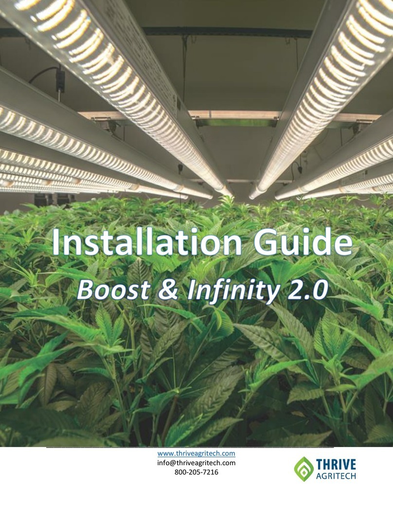
This manual provides installation instructions for the Boost and Infinity 2.0 LED light bars for under canopy
lighting. Instructions are provided for large scale permanent installations as well as temporary test/trial
installations. Please contact customer support with any questions not covered in this guide.
Equipment - Permanent Installation
Required Equipment
•LED Light Bars, Thrive Agritech part number BST-130W-FS2 (recommended) or TBAR-65W-FS2
•Slide & Lock Clips, Thrive Agritech part number SLCLIP, Quantity 2 for each light bar
•Interconnection Clips, Thrive Agritech part number INCLIP-BD, Quantity 1 for each light bar
•Power Cables, Thrive Agritech, several lengths and connector options to choose from
•1.5” x ¼in.-20 bolts & matching nuts, 2 sets for each light bar
•Adjustable trellis mounting structure with steel or aluminum square tubing
oRecommended supplier: Innovative Growers Equipment
(https://www.innovativegrowersequipment.com/plant-support-system-trellis)
oAlternate source of square tubing: Unistrut (https://www.unistrut.us/products/telestrut-
system/telestrut-products)
Equipment - Temporary Test Installation
Required Equipment
•LED Light Bars, Thrive Agritech part number BST-130W-FS2 (recommended) or TBAR-65W-FS2
•Power Cables (Thrive Agritech), several lengths and connector options to choose from
•Interconnection Clips, Thrive Agritech part number INCLIP-BD, Quantity 1 for each light bar
•Structure to support the light bars
oRecommended support: 4”-8” container pot
Optional Equipment
•Unistrut square tubing (https://www.unistrut.us/products/telestrut-system/telestrut-products)
•Slide & Lock Clips (Thrive Agritech)
•¼”-20 bolts & matching nuts, 2 sets for each light bar

___________________________________________________________________________
www.thriveagritech.com
800-205-7216
4
General Guidelines
•Confirm the overall integrity of the light bar prior to installation.
•Maintain at least 8 inches (0.2 meters) between the light fixture and any combustible materials.
•Keep the light fixture away from sources of heat.
•The LED light is an indoor fixture operated within an ambient temperature range of -20oC to 30oC.
•Ensure power is off before installation. Installation must be carried out by qualified electricians.
•To clean the light fixture, switch power off and use a dry cloth without corrosive cleaning agents.
Daisy-Chaining
The maximum number of lights that can be daisy-chained together at various input voltages is shown in the
tables below. Also shown is the nominal current supplied to each fixture. 16AWG wire is recommended.
Boost LED Light
Parameter
120 Volts
240 Volts
277 Volts
Nominal current / fixture
1.1A
0.55A
0.48A
Max # of fixtures linked together in
a daisy-chain
7 fixtures
12 fixtures
16 fixtures
Infinity 2.0 LED Light
Parameter
120 Volts
240 Volts
277 Volts
Nominal current / fixture
0.54A
0.27A
0.23A
Max # of fixtures linked together in
a daisy-chain
10 fixtures
20 fixtures
30 fixtures

___________________________________________________________________________
www.thriveagritech.com
800-205-7216
5
Permanent Installation Instructions
1) Prepare the adjustable trellis support structure as shown in Figure 1. Adjust the square tubing to the
desired height. The lights will be mounted to the square tubing in subsequent steps.
2) For each light bar, attach 2 slide & lock clips (SLCLIP)
to the square tubing using ¼”-20 bolts (Figure 2). A
hole may need to be drilled through the square
tubing for the bolt. The clips should be positioned
approximately 6”-8” from where the ends of the
light bars will be located.
3) Attach the light bars to the main center clips shown
in figure 2 but leave the locking arms disengaged to
allow the lights to slide and connect with each other
(Figure 3).
Figure 1
Square Tubing
Figure 2
Figure 3

___________________________________________________________________________
www.thriveagritech.com
800-205-7216
6
4) Once the lights are connected, attach the interconnection clip (INCLIP-BD) as shown in Figure 4 to
secure the lights mechanically and electrically.
5) Compress the locking arms of the slide & lock clips (SLCLIP) to prevent the lights from moving along
the length of the square tubing (Figure 5).
6) Repeat steps 1-5 for all under canopy lights in the grow room. Note the maximum number of lights
that can be connected (daisy-chained) is shown on page 4 of this guide and on the light bar product
datasheet.
7) Connect power cables to lights.
Locking Arms in
“locked” position
Interconnection Clip
(INCLIP-BD)
Figure 4
Slide & Lock Clip
(SLCLIP)
Figure 5

___________________________________________________________________________
www.thriveagritech.com
800-205-7216
7
Temporary/Test Installation Instructions
For a temporary setup of under canopy lighting for the purpose of testing / trials, a simpler and faster
installation method is often preferred.
1) Place a container pot every 4-feet along the length of the test bench where the connection points of
the lights are anticipated (Figures 6 & 7).
2) Connect two light bars together using the interconnection clip
(INCLIP-BD) as shown in Figure 8 to secure the lights
mechanically and electrically. Place connected light bar
assembly on top of the container pots with the connection
point (interconnection clip) resting on the container pots.
3) Repeat steps 1 & 2 for the entire test bench or test grow room.
4) Connect power cables to lights.
5) Optional: For a more robust and flexible test setup, use the installation method described in the
prior section for a permanent installation.
Figure 6
Figure 7
4”-8” Container Pot
4 Feet
Connection
Point
Interconnection Clip
(INCLIP-BD)
Figure 8
Other manuals for Boost
1
This manual suits for next models
1
Table of contents
Other THRIVE AGRITECH Lighting Equipment manuals
Popular Lighting Equipment manuals by other brands
LED Linear
LED Linear VarioContour 1500 Aluminum Profile installation instructions

TRQ
TRQ ALYA 25 EM PRO AT quick start guide

Matco Tools
Matco Tools MCL12LEDA operating instructions

INTER LIGHT
INTER LIGHT EASYFIT IL-ED3K3D manual

NENKO
NENKO 28037952 manual

Traxon
Traxon Allegro Dot S Direct View installation guide

Digital Sputnik
Digital Sputnik DS series Assembly manual

Coemar
Coemar Risalto Led + user manual

MAC TOOLS
MAC TOOLS MHL600UK Operation and maintenance manual

Larson Electronics
Larson Electronics EPL-LQP-2X150RT instruction manual

Lumie
Lumie Brightspark user manual

TACSWAN
TACSWAN FoxFury EXOLANDER 700-XDS-M2P product manual