THRIVE AGRITECH Boost User manual


___________________________________________________________________________
www.thriveagritech.com
800-205-7216
1
Table of Contents
Introduction.......................................................................................................................................... 2
General Guidelines............................................................................................................................... 2
Daisy-Chaining...................................................................................................................................... 2
Installation Instructions: Flush Mount ............................................................................................... 3
Installation Instructions: Suspension Mount ..................................................................................... 8

___________________________________________________________________________
www.thriveagritech.com
800-205-7216
2
Introduction
This manual provides installation instructions for Boost and Infinity 2.0 LED light bars for top lighting. For
under canopy lighting, use “Installation Guide, Under Canopy Lighting” located on Thrive Agritech’s website.
General Guidelines
•Confirm the overall integrity of the light bars prior to installation.
•Maintain at least 8 inches (0.2 meters) between the light fixture and any combustible materials.
•Keep the light fixture away from sources of heat.
•The LED light is an indoor fixture operated within an ambient temperature range of -20oC to 30oC.
•Ensure power is off before installation. Installation must be carried out by qualified electricians.
•To clean the light fixture, switch power off and use a dry cloth without corrosive cleaning agents.
Daisy-Chaining
The maximum number of lights that can be daisy-chained together at various input voltages is shown in the
tables below. Also shown is the nominal current supplied to each fixture. 16AWG wire is recommended.
Boost LED Light
Parameter
120 Volts
240 Volts
277 Volts
Nominal current / fixture
1.1A
0.55A
0.48A
Max # of fixtures linked together in
a daisy-chain
7 fixtures
12 fixtures
16 fixtures
Infinity 2.0 LED Light
Parameter
120 Volts
240 Volts
277 Volts
Nominal current / fixture
0.54A
0.27A
0.23A
Max # of fixtures linked together in
a daisy-chain
10 fixtures
20 fixtures
30 fixtures

___________________________________________________________________________
www.thriveagritech.com
800-205-7216
3
Installation Instructions: Flush Mount
This guide provides installation instructions using a 4’x16’ canopy as an example. While your specific canopy
may be a different geometry, the same general installation procedures apply. Please contact Thrive Agritech
customer support with any questions not covered in this guide.
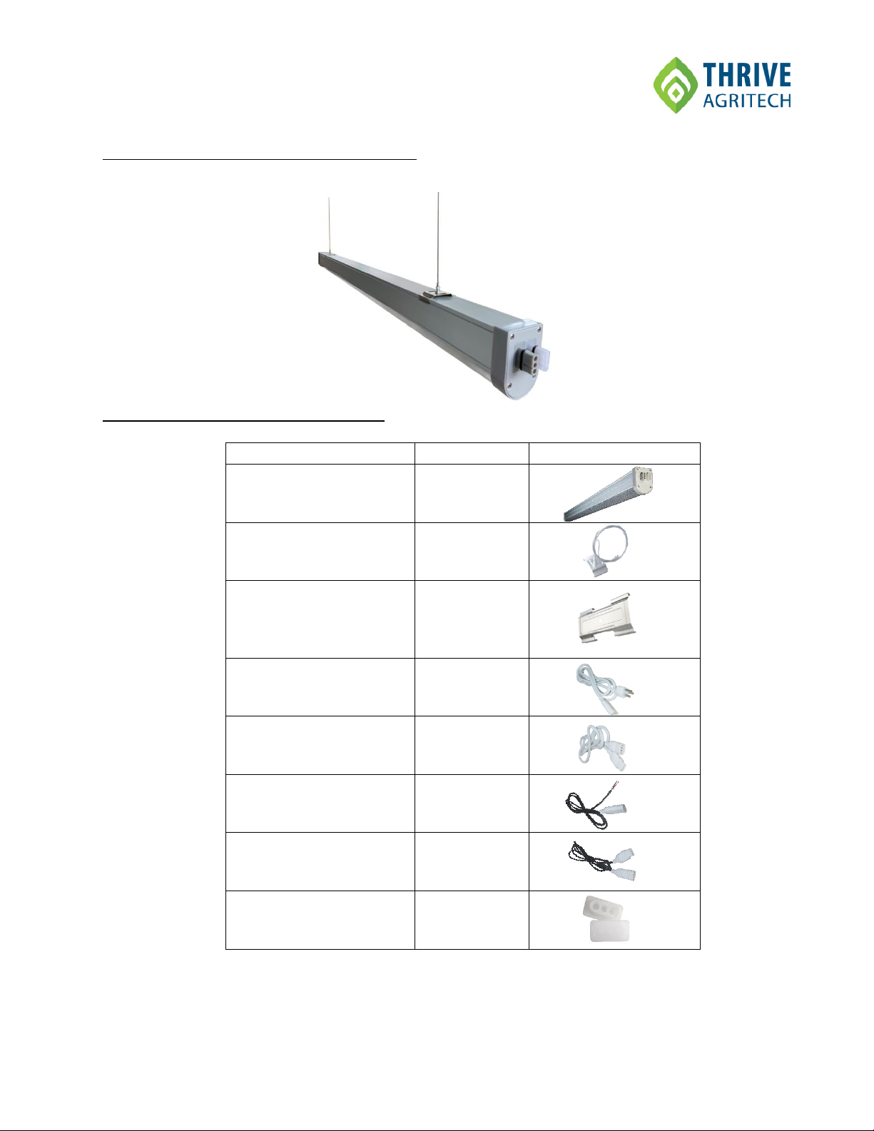
Parts for Flush Mount Installation
Item
Part Number
Image
Website Link
Boost
or
Infinity 2.0
BST-130W-FS2
or
TBAR-65W-FS2
thriveagritech.com/products/
Slide & Lock Clips
SLCLIP
Interconnection Clips
INCLIP-BD
Unistrut
Various
unistrut.us/product-details/p3000t
Cone Nuts
CM-100B-1/2
mscdirect.com/product/details/54055116
¼-20x1.5” machine screws
or
¼-20x1.5” hex bolts
Various
www.grainger.com
Power Cables
BDPCX-XX
Power Interconnection
Cables (optional)
BDINCX-XX
Dimming Controller Cables
(optional)
DIMPCX-XX
Dimming Interconnection
Cables (optional)
DIMINCX-XX
End Caps
ENDCAP-BD

___________________________________________________________________________
www.thriveagritech.com
800-205-7216
4
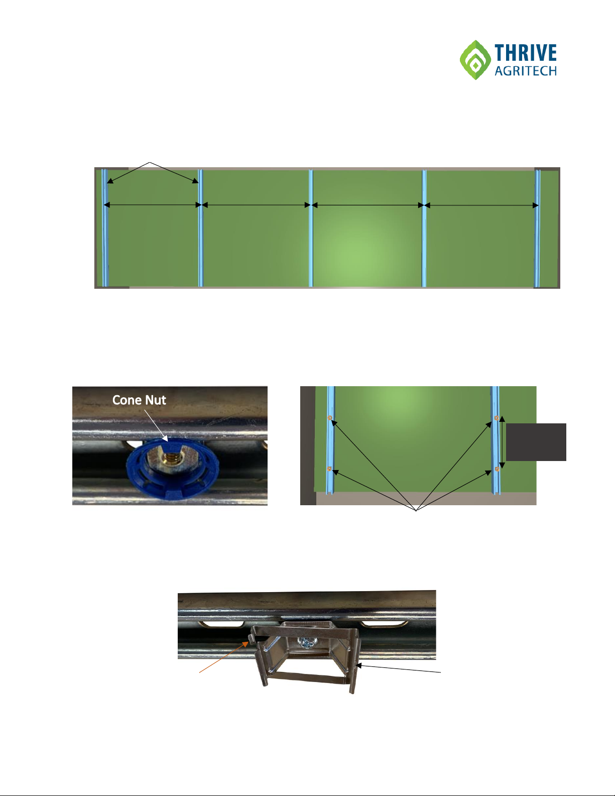
Figure 1 shows the completed installation example of the lights (either Boost or Infinity 2.0) over a 4’x16’
canopy. The installation consists of 4 lines of lights, with each line containing 4 lights connected end-to-end
for a total of 16 lights over the canopy.
Figure 1
___________________________________________________________________________
www.thriveagritech.com
800-205-7216
5
1) Attach the Unistrut bars to the mounting surface as shown in Figure 2. The first two Unistrut bars of
a line of lights should be approximately 36” apart, and all subsequent Unistrut bars should be about
47.25” apart.
2) Slide the cone nuts into the Unistrut bars and position them where the lights will be located (Figures
3 & 4). The center spacing of the light bars must match the lighting design provided by Thrive
Agritech to ensure proper light intensity and uniformity.
3) Position the Slide & Lock clips on top of the cone nuts and secure in place using ¼-20 x 1.5” machine
screws or hex bolts (Figure 5). Ensure all locking arms of the clips are facing the same direction.
36”
47.25”
Unistrut
Figure 2
Figure 4
Cone Nuts
Light bar
Spacing
Figure 3
Figure 5
Slide & Lock Clip
Locking Arm
47.25”
47.25”

___________________________________________________________________________
www.thriveagritech.com
800-205-7216
6
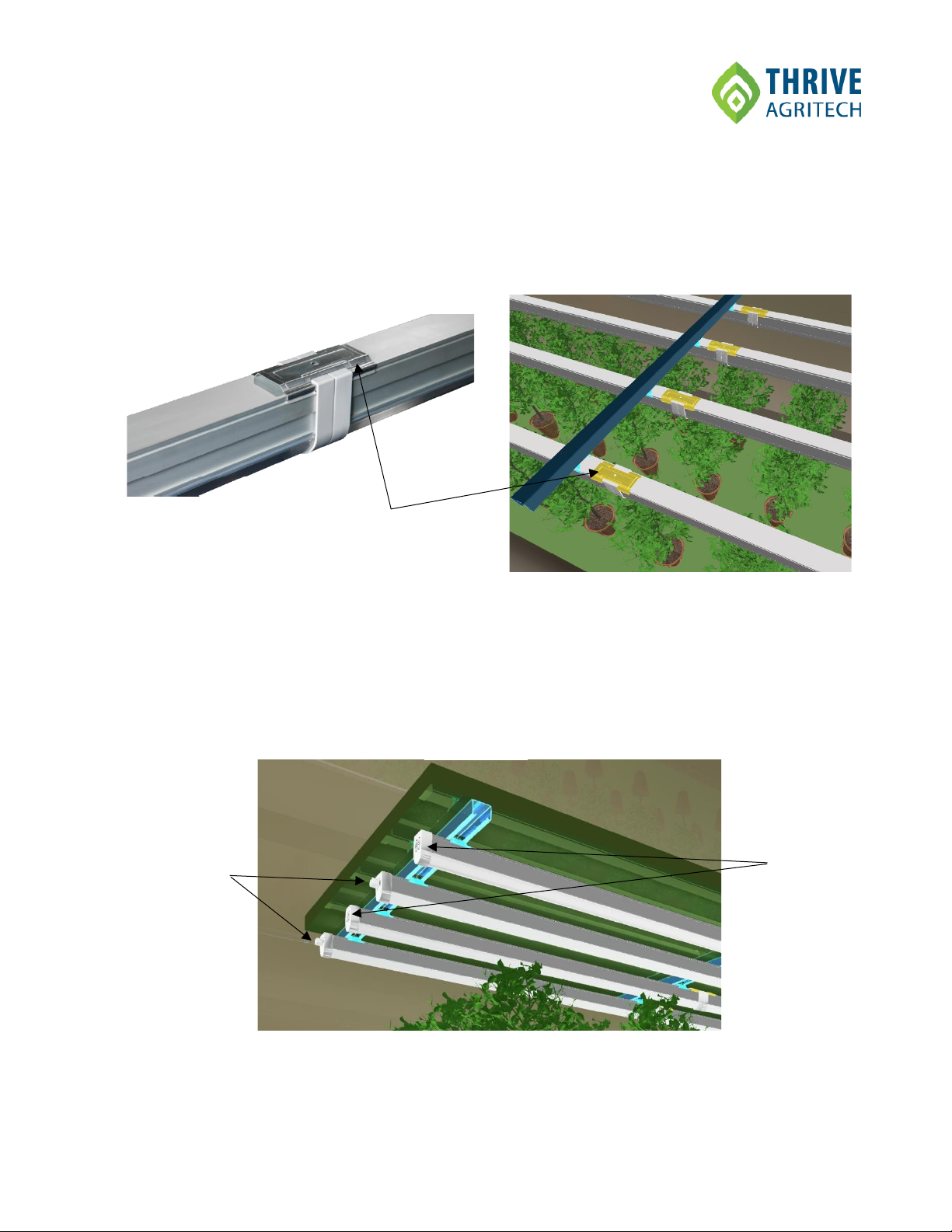
4) Beginning with the Unistrut bars that are spaced 36” apart, secure the lights to the slide & lock clips
as shown in Figure 6, but leave the locking arms disengaged to allow the lights to slide and connect
with each other.
Figure 6
Slide & Lock Clip
___________________________________________________________________________
www.thriveagritech.com
800-205-7216
7
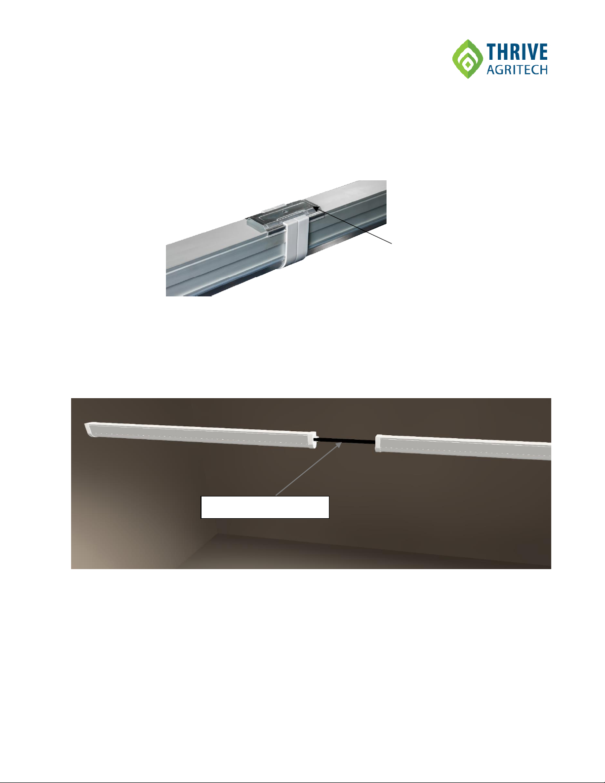
5) Once the lights are connected end-to-end, make any final positional adjustments such as ensuring
the ends of the lights are aligned.
6) Attach the interconnection clip as shown in Figure 7 to secure the lights mechanically and
electrically.
7) Compress the locking arms of the slide & lock clips to secure the lights in place.
8) Connect power cables to lights. Connect optional interconnection cables or dimming cables as
needed. When using interconnection cables to electrically connect fixtures side by side, ensure the
fixture direction is alternating male to female (Figure 8).
9) Cover any exposed connectors with the end caps.
Interconnection Clip
Figure 7
Female
Connectors
Male
Connectors
Figure 8
___________________________________________________________________________
www.thriveagritech.com
800-205-7216
8
Installation Instructions: Suspension Mount
In some circumstances, customers may prefer to install Boost or Infinity 2.0 lights using suspension
cables.
Parts for Suspension Mount Installation
Item
Part Number
Image
Boost
or
Infinity 2.0
BST-130W-FS2
or
TBAR-65W-FS2
Suspending kit
SKIT-BD
Interconnection Clips
(optional
INCLIP-BD
Power Cables
BDPCX-XX
Power Interconnection
Cables (optional)
BDINCX-XX
Dimming Controller Cables
(optional)
DIMPCX-XX
Dimming Interconnection
Cables (optional)
DIMINCX-XX
End Caps
ENDCAP-BD
___________________________________________________________________________
www.thriveagritech.com
800-205-7216
9
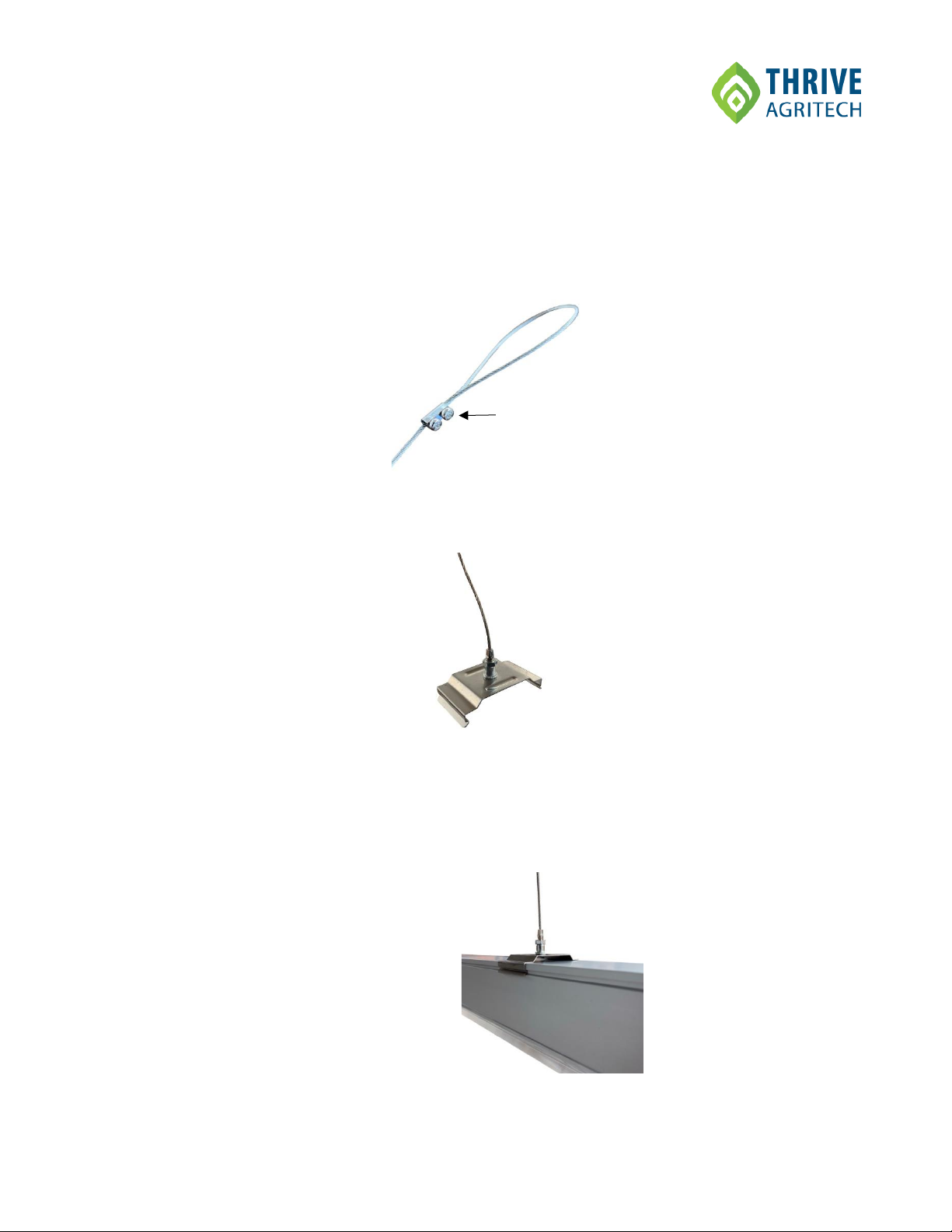
1) Unpack the suspending kit (SKIT-BD) clips and cables.
2) Loosen of the cable screws for each cable and adjust the length of the cables so the lights will
hang at the desired height above the canopy. The cables are normally all set to the same length.
After setting the cables to the appropriate length, tighten the cable screws to lock in place.
Figure 9
3) Attached the suspension clips to the cables using the provided screw (Figure 10).
Figure 10
4) Secure the suspension clip & cable assemblies to the mounting structure (e.g., Unistrut, eye
bolts, hooks, etc.) at the positions above the canopy as specified in the lighting design. The cable
assemblies should be positioned so that two (2) suspension clips can attach to the light bar
approximately 6”from each end of the light.
5) Attach the Boost or Infinity 2.0 light bar to the suspension clips (Figure 11).
Figure 11
Suspension Clip
Cable Screws
___________________________________________________________________________
www.thriveagritech.com
800-205-7216
10
6) The lights are frequently electrically and mechanically daisy-chained by mating the ends
together. If creating end-to-end connections, attach an interconnection clip (INCLIP-BD) at the
connection point between the lights –Figure 11.
Figure 11
7) Connect power cables to lights. Connect optional interconnection cables or dimming cables as
needed. Lights that are physically separated may be electrically daisy-chained using
interconnection cables. Be sure not to exceed the maximum number of connected lights when
daisy-chaining (see page 2 of this guide or the product datasheet for the light.
8) Cover any exposed connectors with the end caps.
Interconnection Clip
Interconnection Cable
Other manuals for Boost
1
This manual suits for next models
1
Table of contents
Other THRIVE AGRITECH Lighting Equipment manuals

Popular Lighting Equipment manuals by other brands


SLV
SLV 113150/51 operating manual

superbrightleds
superbrightleds XS-RG user manual

Lightmybricks
Lightmybricks LEGO SANTA'S VISIT 10293 installation guide

Lightmybricks
Lightmybricks LEGO IMPERIAL LIGHT CRUISER 75315 LIGHT KIT installation guide

HQ Power
HQ Power VDL660RL user manual

Compu Pool Products
Compu Pool Products C-CPP Series owner's manual