Thwaites SPRITE NIMBUS User manual

SPRITE
NIMBUS

NIMBUS & SPRITE DUMPER
IN THE INTEREST OF SAFETY THE DUMPER SHOULD NOT BE DRIVEN IN A
MANNER WHICH EXCEEDS THE LIMITS SHOWN BELOW.
FOR UNLADEN DUMPER:
• MAXIMUM PAYLOAD - 15 CWT. OR 762 Kg.
• LOAD WITH CARE - BULKY, HIGH LOADS ARE DANGEROUS. THEY MAY MAKE
THE DUMPER UNSTABLE AND MAKE IT DIFFICULT FOR THE DRIVER TO SEE THE
ROAD AHEAD.
• REMEMBER - THE LOWER THE POSITION OF THE LOAD THE SAFER THE
DUMPER.
• TAKE CARE WHEN USING STARTING HANDLE
WRONG RIGHT
WARNING: DO NOT ATTEMPT ANY ADJUSTMENTS OR MAINTENANCE UNDER
A RAISED SKIP UNLESS IT IS SECURELY PROPPED.
PLACE FINGERS AND
THUMB ON THE
SAME SIDE OF
HANDLE.
DO NOT HOLD HANDLE
WITH FINGERS ON ONE
SIDE AND THUMB ON THE
OTHER.

SERVICING INSTRUCTIONS
NIMBUS & SPRITE MODELS
CONTENTS:
A OPERATION & ROUTINE MAINTENANCE
B SERVICING POINTS
1 CLUTCH
2 GEARBOX
3 AXLES
4 DRIVE SHAFT
5 STEERING GEAR
6 OIL BATH AIR CLEANER
7 MAINTENANCE CHECK OFF LIST

THWAITES SPRITE/NIMBUS - OPERATION AND MAINTENANCE INSTRUCTIONS
Whilst every endeavour has been made to ensure that your dumper is delivered to
you ready to commence work, it is advisable before putting machine on site to have
the following check carried out:-
1. Check oil level in engine.
2. Check oil level in gearbox.
3. Check oil level in axle.
4. Check oil level in steering box.
5. Fill tank with clean fuel.
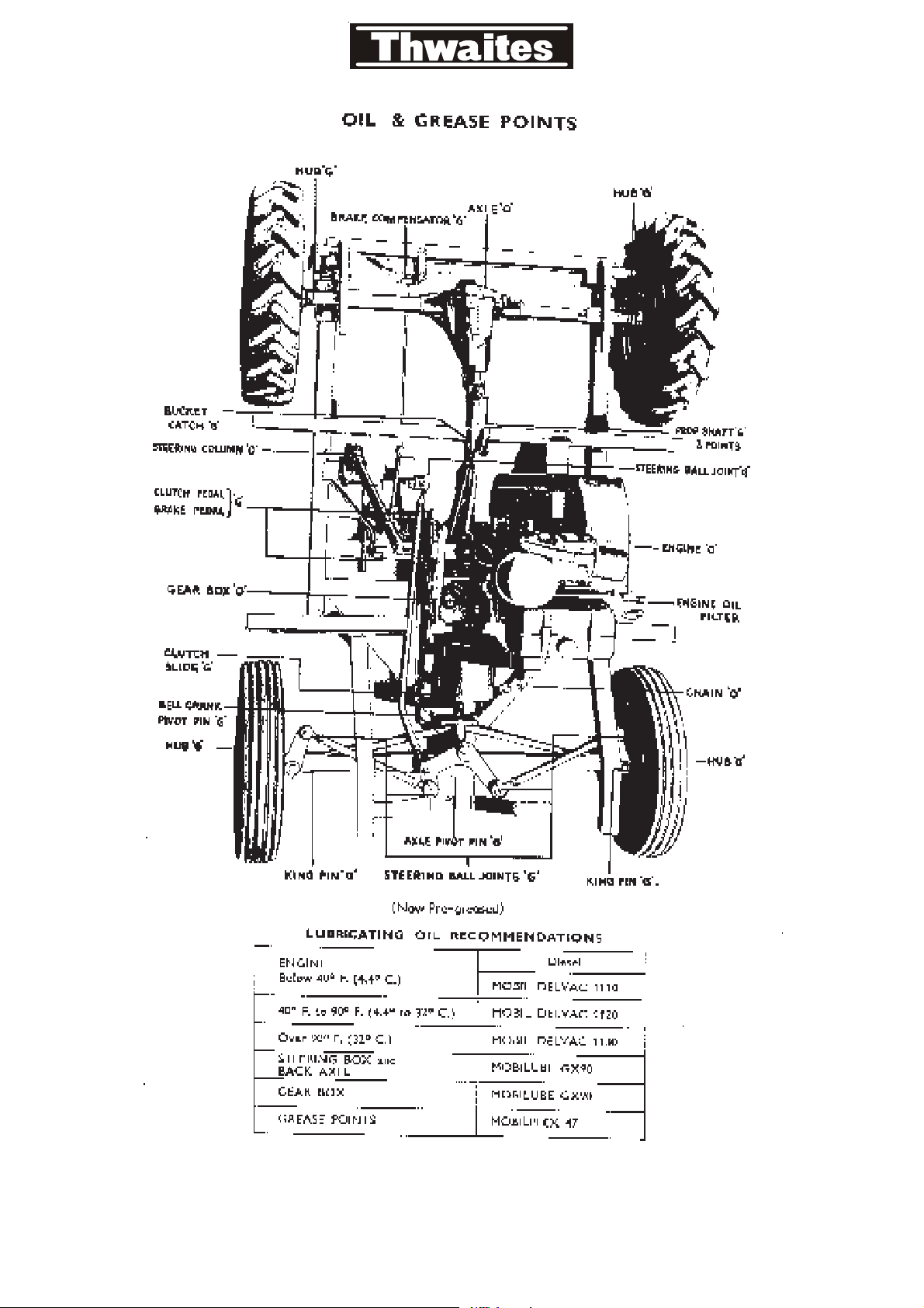
6. Check tyre pressures: Sprite model - front 30 p.s.i. rear 20 p.s.i.
Nimbus model - front 28 p.s.i. rear 20 p.s.i.
7. Lubricate driving chain.
8. Grease machine.
To start the engine see engine manufacturer’s handbook. Starting handle located on
the right hand side of engine.
DRIVING THE DUMPER
• Adjust the seat until controls can be reached with ease.
• The gear lever is situated to the right of the seat and the positions are marked on the
knob.
• The pedal positions are the same as a car, i.e. clutch pedal to the left of the steering
column, brake pedal to the right of the steering column, throttle pedal to the right of
the brake pedal.
• The handbrake is to be found on the right of the seat.
• Gear changing may be carried out while machine is moving.
• DO NOT drive machine with foot resting on clutch pedal.
• DO NOT use top (3rd) gear while on rough site.
To tip the skip push the lever (which is situated to the right and down by the throttle
pedal) in a downwards direction. To return skip to horizontal position pull the skip
back by means of handle on skip. There is no need for driver to leave his seat for the
operation.
MAINTENANCE AND RUNNING ADJUSTMENT:
Engine - Full instructions for maintaining the engine at full efficiency are given in the
engine manufacturer’s handbook supplied with each dumper. It is advisable to have
the engine over-hauled periodically by a skilled mechanic, and any major troubles
should be referred to the engine makers or our own service department.
(A)

CLUTCH ADJUSTMENT (See Illustration)
Depress clutch pedal to its full amount of travel, then turn the square headed screw
on the clutch back plate in a clockwise rotation until tight, then turn back until clutch
unit revolves freely. DO NOT adjust clutch by the wired nut, as this is pre-set at
works to give correct spring tension.
CHAIN ADJUSTMENT
Slacken the engine mounting bolts, and move the engine over to the right. Never
adjust the chain too tight, slight up and down movement is necessary. Always keep
chain well oiled.
BRAKE ADJUSTMENT
Release handbrake and turn the square headed screw located on the brake back
plate in a clockwise direction until tight, and then turn back until wheel revolves
freely.
If working in very dirty conditions it is advisable to strip and clean brakes
periodically i.e. at least once per week. To do this jack up and remove wheels,
release brakes and remove brake drum. (The wheel and wheel nuts hold the brake
drum on the hub).
GENERAL MAINTENANCE
It is extremely important that the dumper be kept clean, if cleaned regularly it
facilitates easy greasing and general maintenance. When working with concrete,
machine should be hosed down and all surplus concrete etc. removed before it goes
hard. Having cleaned the dumper the following maintenance should be carried out:-
Daily: Check oil in engine.
Fill fuel tank with clean fuel.
Oil chain and all moving parts.
Weekly: Remove oil filter, clean and refill with oil.
Remove air filter and clean.
Remove fuel filter and clean.
Check chain adjustment.
Check clutch adjustment.
Check tyre pressures.
Grease all points thoroughly and wipe the machine down with oily rag.
Monthly: Change engine oil and filters, see engine handbook.
Change gearbox oil - 1¾ pints.
Change axle oil - 6½ pints (Nimbus) 4 pints (Sprite)
Change steering box oil - 2/3 pints.
(B)
(B)

Turn square headed screw in clutch back plate for adjustment
1-1
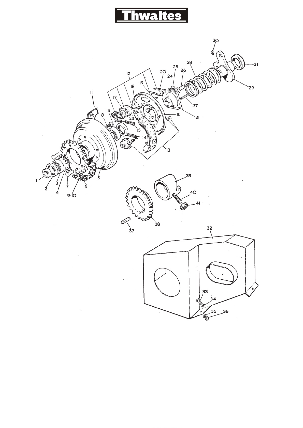
CLUTCH AND HOUSING
1-2

SERVICING THE CLUTCH - SPRITE/NIMBUS MODELS
DISMANTLING:
1. Remove the floorboard.
2. Disconnect the clutch operating arm, unbolt and remove the chainguard (item 32).
3. Remove the locking wire from the conical nut (item 18), compress the clutch slide
(item 29) and unscrew the conical nut (item 18), care should be taken when
releasing the clutch slide as spring tension is considerable.
4. DO NOT touch the 4 clutch mounting bolts (items 22 & 23) on the clutch centre
(item 21). It will be noted that 2 of the bolts are longer, these are for the attachment
of the clutch extractor.
5. Using the extractor withdraw the clutch off the shaft, after the first 2 inches the
centre will pull off freely. Look out for the key (item 27) as it can quite easily fall out
and get lost.
6. Take notice of the position of the clutch shoes (item 11). If refitted incorrectly, clutch
slip will take place, and shoes will wear quickly. Clean the backplate down, grease
the adjuster (item 13) and expander unit (item 12), very lightly remove any excess
grease, make sure that expander is free to move on backplate.
7. Refit clutch shoes and spring. Check the four mounting bolts for tightness.
ASSEMBLING:
1. Locate the key in the keyway (item 27) of the shaft, lightly grease the shaft. Put the
clutch on the shaft, line up the key and keyway and press clutch on until solid.
2. Grease the clutch slide (item 29) and guide rod (item 26), now fit the clutch spring
(item 28) and slide (an easy way of fitting the clutch spring is to compress the clutch
spring in a vice and wire it up. The wire must be cut and removed after the conical
nut has been screwed up, but before final adjustments are made).
3. Compress the clutch slide until the clutch spring is solid, and screw up the conical
nut until coned seat is 1/64" clear of hole.
4. Operate the clutch 2 or 3 times to centralise the shoes then hold the slide in the fully
compressed position and adjust the clutch i.e. Turn the square adjuster screw in a
clockwise direction until tight then slacken off until clutch revolves freely.
IMPORTANT: Wire the conical nut to the clutch slide, refit the chain guard and
clutch operating arm. The gap between the clutch operating arm and the clutch
thrust bearing (item 31) should be 5/16" when the clutch is fully adjusted. When
clutch has been relined it is advisable to re-adjust after 2 or 3 days work.
DO NOT allow the gap between the clutch operating arm and the clutch thrust
bearing to close, this will cause clutch slip. It is advisable to adjust clutch when the
gap closes to 1/8".
To adjust the clutch on site, a special clutch adjusting spanner is provided with each
machine. Two people are required, one to sit on the machine and depress the clutch
pedal, the other to adjust the clutch.
Engage starting handle in starting dog, turn handle until the square headed
adjusting screw is in line with the cut out on the face of the chain guard, insert
special spanner and adjust as described in previous paragraph.
1-3

1-4
2 ton model only
CLUTCH ROD
PIVOT
CLUTCH CLUTCH ROD
STOP
CLUTCH
All other models
PIVOT
CLUTCH SLIDE (Item 102)
CLUTCH SLIDE
NUT OR CONICAL NUT
(Item 91)
LOCKING
WIRE
SPRING (Item 101)
SLIDE ROD TO
BACK PLATE
BEARING (Item 104)
(CLUTCH THRUST)
CHAINCASE (Item 109)
CLUTCH OPERATING
ARM OR LEVER
'A' - 1/64" ALL
MODELS
'B' (1) 7" DIA CLUTCH
2 TON - 9/16"
TUSKER - 1/2"
ORION - 1/2"
(11) 6" DIA CLUTCH
SPRITE - 3/8"
NIMBUS - 3/8"
'A'
'B'

PRECAUTIONS AFTER RE-ASSEMBLY
IMPORTANT: Wire the conical nut to the clutch slide, refit the chain guard and
clutch operating arm. The gap between the clutch operating arm and the clutch
thrust bearing should be 9/16" when the clutch is fully adjusted (2 ton model).
Dimensions for Sprite, Nimbus, Orion and Tusker machines - see system drawing -
refer to dimension ‘B’.
When clutch has been relined it is advisable to re-adjust after 2 or 3 days work.
DO NOT allow the gap between the clutch operating arm and the clutch thrust
bearing to close, this will cause clutch slip. It is advisable to adjust clutch when the
gap closes to ¼" on the 2 ton Alldrive and 1/8" on all other models.
To adjust the clutch on site, a special clutch adjusting spanner is provided with each
machine. Two people are required, one to sit on the machine and depress the clutch
pedal and the other to adjust the clutch.
Engage starting handle in starting dog, turn handle until the square headed
adjusting screw is in line with the cut out on the face of the chain guard, insert
special spanner and adjust as described in previous paragraph.
The clutch unit illustrated is that fitted on the 2 ton Alldrive machine.
NOTE: Ideal working clearance for dimension ‘A’ is 1/64". More than 1/64" results in
excessive clutch wear.
SERVICING NOTE: (Bearings Item 76).
It is advisable that the clutch drum bearings are packed with high melting point
grease every 12 months.
7-1-13

GEARBOX ASSEMBLY T5260
SPRITE & NIMBUS

SERVICING 40M-3 GEARBOX - SPRITE/NIMBUS MODELS
GENERAL:
1. Cleanliness is important. Remove all loose dirt and see that all bolt heads are clear
of cement, etc. outside the gearbox before any inner part is exposed. Drain the oil
from the gearbox.
2. Use a mandrel press, if available, for pressing out bearings, shafts, etc., otherwise
use hardwood or non-ferrous metal drifts.
3. Wash all parts in clean paraffin or petrol and lightly oil before reassembly. If new
ballraces are being fitted, do not remove wrappings until they are needed for
assembly.
4. Work on a clean bench.
GEARBOX WITH PLAIN INPUT AND OUTPUT:
1. Undo the four bolts (item 10), securing the front extension cover (item 8) and
remove bolts. Undo and remove the top cover and gear lever assembly complete.
Using a suitable lever, move the selector forks (item 79) and (item 52) so that two
speeds are engaged simultaneously. The gear train should now be locked, and will
not rotate.
2. Untab the bolt (item 60) which secures the output coupling and remove the bolt.
Slack off the six bolts (item 34) and (35) securing the end cover (item 29) and
remove it, also remove the output coupling (item 33) and spacer (item 30).
REMOVE SELECTOR FORKS AND MECHANISM:
1. Undo and remove the bolt (item 80) and retaining plate (item 75) on the back of the
gearbox. Drive forward the upper selector shaft (item 55), through the fork and the
front of the gearbox. Inside the fork is a ball and spring. Unless care is taken the ball
may fall out into the body of the gearbox. As soon as the shaft has left the fork, close
the ends of the hole in the fork with the fingers, and remove complete from the
gearbox. Now undo the split pins in the clevis pins (item 48), remove the clevis pins
and baulk plate, and then remove the lower shaft and fork in the manner described
above.
REMOVAL OF GEARSET:
1. Undo and remove the bolts (item 10) holding the front extension housing. Remove
the extension housing and primary shaft assembly complete. It may be necessary to
use a lever between the head of the primary shaft and the mainshaft to do this. Take
care not to damage the gear teeth in so doing.
2. The mainshaft is now pressed out through the front of the gearbox. The gears and
spacers on the mainshaft are removed from the back end of the mainshaft, one by
one, after it has cleared its supporting ballrace in the back of the gearbox.
3. Remove the circlip (item 58) securing the mainshaft ballrace, and press out the race.
Remove the circlip (item 69) and the circlips (item 68) from the end of the layshaft.
Now reverse the box, and using a drift which is nearly the same diameter as the
bronze bearing (item 76) drive the layshaft and bearing back until the bearing is
clear of the gearbox. If too small a drift is used, the end of the bronze bush will be
collapsed and the bush will be spoiled.
4. Place two plates about 1/8" thick between the ballrace and the gearbox and press the
layshaft back into the gearbox, thus removing the ballrace. Alternatively a suitable
pulley extractor may be used. Now remove the spacer and reverse layshaft gear via
the ballrace bore in the case, and the remainder of the layshaft assembly can be
removed from inside the gearcase via the top opening.
2-2

SERVICING 40M-3 GEARBOX - SPRITE/NIMBUS MODELS
REMOVAL OF GEARSET: (CONTD.)
5. Undo the nut (item 63) on the reverse pinion shaft and remove the reverse pinion
assembly.
6. The main dis-assembly of the gearbox is now complete.
7. Removal of the circlip from the front part of the lay shaft will enable the forward
part of the layshaft assembly to be slid off.
** REMOVAL OF PRIMARY SHAFT BEARING:
1. Only remove this bearing when replacement is required as it is frequently spoiled in
removal. Remove the circlip (item 24) and spacer (item 25). Press the ballrace back
until the oil hole in the primary shaft is covered by it. Now fill the primary shaft
bearing with very heavy oil or grease. Support the primary shaft rigidly and
vertically. Use a drift which is the same bore diameter as the worn bush. Enter it into
the bearing and strike it a number of heavy blows. The bearing will be forced out by
the hydraulic action of the grease.
RE-ASSEMBLY OF SMALL COMPONENTS:
1. If the gearbox has been used on continuous heavy duty it is advisable to replace
ballraces and oil seals as a matter of course. New oil seals should be fitted by
pressing them in with a flat steel plate which covers their entire area, otherwise they
may buckle and be spoiled. Output couplings frequently show heavy wear where the
oil seal has contacted them. When this condition is observed, the coupling should
be replaced.
2.** A new primary shaft bush must be pressed in with a suitable drift and then reamed
in position with a 5/8" diameter reamer. The pilot diameter of the mainshaft should
be a free running fit without undue shake.
3. The shafts and gears in the gearbox are treated with a phosphating process in order
to ensure satisfactory performance. Do not attempt to remove any apparent
discolour-ation by polishing bearing surfaces on shafts or in the bores of gears as
seizure may result from the exposure of naked steel surfaces.
4. If the reverse idler gear is rebushed, this bush (item 67) is the correct size when
pressed in, and will not need any further treatment. If this gear has been re-bushed,
then re-placement of the reverse idler shaft (item 62) is also advised.
** This applies up to serial no. 40427 whence a needle roller bearing was fitted.
RE-ASSEMBLY OF MAIN GEARBOX:
1. The case should be clean inside and out.
2. Fit the layshaft bush (item 76) with the slot on the outside of the bush at the top.
3. Fit the reverse idler gear assembly complete, the woodruff key (item 61) is most
important. The gear (item 66) should be a free running fit when the reverse shaft has
been fully tightened up.
4. The layshaft (item 73) should now be partly sub-assembled. Fit the inner first speed
gear (item 72b), layshaft gear (item 78) and secure with circlip (item 24). Check that
the gear (item 72b) has at least .007" end float. Slip on the sliding gear (item 74, and
insert this sub-assembly, through the top of the gearbox into its correct position,
locating it in bush (item 76). Through the ballrace bore in the back of the case, insert
the reverse gear which is part no. T4558 (item 72a) and the spacer T4548 (item 71).
2-3

SERVICING 40M-3 GEARBOX - SPRITE/NIMBUS MODELS
RE-ASSEMBLY OF MAIN GEARBOX: CONTD.
5. Before pressing the ballrace into place, the layshaft must be supported by placing a
steel packing about 3/8" thick between the gear (item 78) and the casing, otherwise
the bush (item 76) will be driven out, and it will not be possible to press the ballrace
(item 70) into place. With the ballrace pressed fully home, and the circlip (item 68)
fitted, remove the packing and fit the snap ring (item 69). This positions the layshaft
correctly.
6. Now fit the mainshaft ballrace (item 57) and its circlip (item 58). Pass the mainshaft
through the front of the gearbox, and feed on, in this order, the sliding gear (item
44), the second speed gear (item 56), the spacer (item 40), and the output gear (item
39), (with the narrow boss outwards). They must all be located on their correct shaft
diameters as the shaft is entered into the ballrace. Press the shaft home.
7. Fit the primary shaft (item 26) and front extension housing (item 8).Important:
Note: the oil feed hole in the gasket (item 21) and the extension housing. These must
be properly aligned with the oil feed hole in the case. Fit the lower selector fork
(item 79) and shaft (item 55). It is an advantage when fitting the selector forks, to use
a short piece of ½" diameter rod, fitted through the fork to retain the ball and spring
in position. The fork, with the rod in place, is passed into the box, and the selector
shaft is then pushed through from the rear of the case, and the fork, pushing out the
piece of ½" rod in the process. Secure the shaft by means of the retaining plate (item
75) and position the fork in the neutral position. Fit the interlock plate (item 50) and
pick up one of the interlock studs (item 51) with a clevis pin. If the slot in the fork is
not in line with the plate adjust the position of the plate by screwing up or
unscrewing the interlock stud to correct the error. Adjust the opposite interlock stud
to suit, fit the remaining clevis pin and split pin up. The upper fork and shaft are then
fitted in a similar manner to the lower one. The retaining plate (item 75) being
removed and refitted so that it secures both shafts.
8. When this is correct the Welch plugs (item 77) should be smeared with suitable
sealing compound and driven home. NB. item 77 - sealing discs.
9. Move both selector forks, so that two speeds are engaged, and the gear train locked.
Fit spacer (item 30), refit the end cover (item 29) in its correct position, fit coup-ling
(item 33) and washers, and tighten and tab the coupling bolt. Put the forks back in
neutral and fit the top cover and gear lever assembly. If the flats on the sides of the
pivot ball are worn, or if the spring retaining plate (item 47) is worn on the
under-side, they should be replaced.
10. Check that each speed is easily obtained, and that the gearbox rotates freely in all
speeds.
2-4

SERVICING 40M-3 GEARBOX - SPRITE/NIMBUS MODELS
DISMANTLING THE FRONT EXTENSION HOUSING:
1. Support the extension housing on the underside of the flange with a suitable ring
which will permit the input shaft (item 26) and bearing (item 23) to pass through.
Press the input shaft through from the driven end.
2. Removal of the input shaft will permit spacer (item 15) and ‘0’ ring (item 16) to be
removed.
3. By inverting the extension housing and supporting it such that the oil seal (item 17)
and bearing (item 18) may pass through and by using a drift slightly smaller than the
bore of the housing, the bearing and oil seal may be pressed out.
4. The bearing (item 23) can be removed from the input shaft by removal of circlip
(item 24) and the spacer (item 25) and supporting the bearing by a cylinder which
permits the input shaft to be driven freely through.
5. The front extension housing is re-assembled in a reverse manner to that described
above with new ‘0’ ring and oil seals and bearings (where necessary).
6. All parts to be fitted must be cleaned thoroughly. Ensure gearbox rotates freely in all
speeds.
7. Before placing into service the gearbox requires filling with 1½ pints of oil.
2-5

CONTENTS OF AXLE SERVICING - SECTION 3.
SPRITE AND NIMBUS MODELS
(a) INTRODUCTION & PRECAUTIONS, AXLE OIL CAPACITIES, AXLE CODE
and WHEEL NUT TIGHTNESS.
(b) DIAL GAUGE and AXLE END-FLOAT MEASUREMENT.
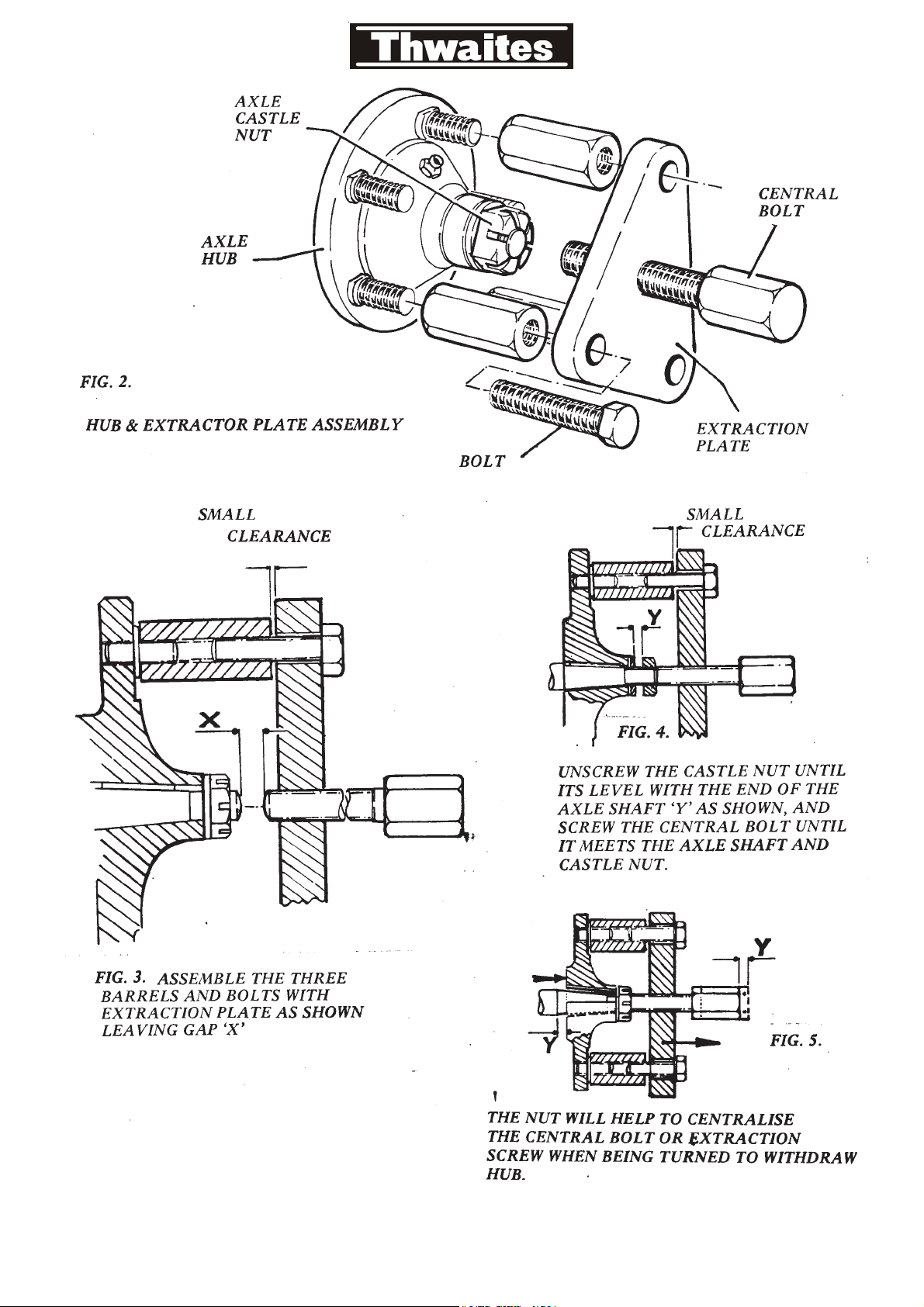
(c) HUB EXTRACTION TOOLS.
3-1-0 AXLE ASSEMBLY DRAWING
3-1-1 REMOVAL OF AXLE SHAFT
3-2-0 REMOVAL OF THE DIFFERENTIAL ASSEMBLY
3-2-1 (PARA: 9) REMOVAL OF GEAR and BEARINGS
3-2-1 (PARA: 12) REMOVAL OF PINION
3-2-2 (PARA: 16) REMOVAL OF OIL SEAL and BEARINGS
3-2-5 (PARA: 19) DISMANTLING OF THE DIFFERENTIAL
3-2-5 (PARA: 20) RE-ASSEMBLY OF THE DIFFERENTIAL
3-2-6 (PARA: 21) RE-ASSEMBLY OF PINION
3-2-9 (PARA: 33) CORRECT POSITION FOR PINION SETTING
3-2-10 CHART 1 - MEASUREMENT OF PINION SETTING
3-2-12 CHART 2 - TORQUE TIGHTNESS
3-2-14 (PARA: 39) RE-ASSEMBLY OF GEAR and BEARINGS IN DIFF.
3-2-15 (PARA: 43) CORRECT USE OF SHIMS FOR PACKING
3-3-1 CHART 3 - TOOTH CONTACT ON DRIVE GEAR
3-3-2 BACKLASH - CORRECT PROCEDURE FOR ADJUSTMENT

INTRODUCTION:
The following details within this section deal with the important aspects of axle
servicing and it is essential that the servicing procedure for the relevant axle be
adhered to.
The correct servicing as shown by illustration and text, will ensure correct running
and a longer service life for the axle.
Wherever possible all service repairs should be carried out through the offices of
the dumper manufacturers. If for any purpose this is not possible, these service
instructions are issued as a guide.
It should be noted that an hypoid axle is dependent for its efficient functioning on
the correct settings for the component parts. It is not considered that certain items
can be serviced successfully in the field and it is recommended that the service
instructions outlined in this manual are completed under workshop conditions using
correct equipment as recommended.
Certain components should always be renewed when servicing axles, these are
stated in the text, however, any component which is found to be damaged must also
be replaced.
NOTES ON LUBRICATION:
Lubrication of hypoid gears:
Hypoid gears need special Hypoid Lubricants. It is absolutely essential to use an
Extreme Pressure HYPOID lubricant of approved type in the SAE 90 classification
and conforming to the requirements of S.S. Specification MIL-L-2105B.
Thwaites Engineering Co., Ltd., do not approve the addition of any proprietory
compounds to the oils recommended, as all these oils have been individually
compounded from specified base oils and additives in definite proportions, and any
addition to these lubricants could result in dangerous dilution, or gear failure.
AXLE OIL RECOMMENDED - MOBIL HD 90 replacing GX 90.
AXLE OIL CAPACITY - 4 pints.
AXLE MANUFACTURERS CODE: - 4HA.
AXLE WHEEL NUT TIGHTNESS: 150 lbs.f.ft.
AXLE SHAFT END-FLOAT: 0.003" to 0.008"
3(a)
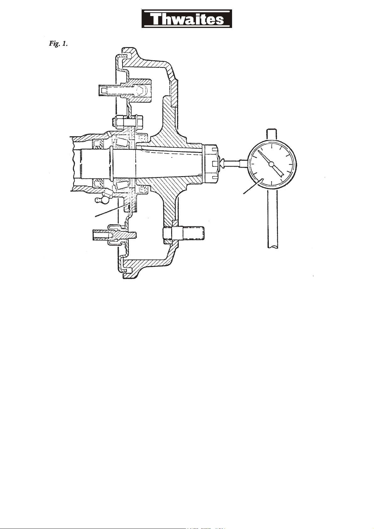
Axle Shaft
End Float
Measurement
dial
gauge
shims
3(b)
Other Thwaites Construction Equipment manuals

Popular Construction Equipment manuals by other brands

Saferoad
Saferoad VIKOrsta SafeLine-R installation manual

APW Wyott
APW Wyott GB Cyclone B2000 instruction sheet

probst
probst RVD-4,5-ECO operating instructions

Gloria
Gloria Profiline 415 Series user manual

Stone
Stone Mud Buggy SB1600 Service & parts manual

Altrad Belle
Altrad Belle RTX 50 Operator's manual

Storch
Storch DMS 25 PRO manual

zarges
zarges Z200 Assembly and usage instructions

Manitou
Manitou MRT EASY 55P 400 ST4 S2 Operator's manual

Farmi Forest Corporation
Farmi Forest Corporation CR40 OPERATION, MAINTENANCE AND SPARE PARTS MANUAL

Hyundai
Hyundai HL960A Operator's manual

SPIERINGS
SPIERINGS AT7 manual


